M-88
FORMING CHARACTERISTICS OF TAILORED BLANKS
IN THE DEEP DRAWING PROCESS
Tri Widodo Besar Riyadi
1Department of Mechanical Engineering, Muhammadiyah University of Surakarta Jl. A. Yani Tromol Pos 1 Pabelan Kartasura 57102 Telp 0271 717417 ext 222
Email: [email protected]
Abstract
Demand for lightweight vehicles is growing in a rapid swiftness primarily because of economical and environmental reasons. By reducing the weight of the vehicles, the fuel consumption and emissions are considerably reduced as well. For weight and cost reduction, the technology of tailor-welded blanks (TWBs) is a promising technology for both automotive and aerospace sectors. In this technology, some pieces of sheet metals are welded together prior to the forming. Since the tailored blank is composed from different sheet metal having different sheet thickness as well as its properties, the forming of tailored blank then creates a lot of technical problem especially in the scheme of deformation. The objective of this paper is to investigate the material flow and the strain distributions of tailored blanks during the forming process.
Deep drawing of a cylindrical cup from tailored blanks was done in order to observe the influence of the hardening of the weld on the material flow of the tailor-welded blanks. Punch diameter was 50 mm and initial blank diameters were 150 mm.
The result of experiment shows that flow of tailor-welded blanks in a process of deep drawing is considerably different from the flow of homogeneous blanks. Wrinkling has been appeared in the thinner wall Another effect present in drawing of tailor welded blanks made from the base materials of different strength or thickness is a movement of the weld line towards the material of greater strength or thickness.
Keywords:Deep Drawing; Tailored Blank; Forming Behaviour
Introduction
In conventional vehicle production process, body panels are usually made up of several smaller components which then is formed individually and subsequently welded together to create the desired body shape. This method incorporates high tooling and material costs. Moreover this approach contributes to the dimensional inaccuracy in the assembly process. The use of Tailored Blanks offers an advantageous with respect to product, process and design, since the body panels can be formed in a single stamping process.
A Tailored Blank consists of several flat sheets that are welded together before forming. A combination of different materials, thickness, and coatings can be welded together to form a blank for stamping car body panels. The main advantage of using a Tailored Blank is to have specific characteristics at particular parts of the blank in order to reduce weight and costs. Particular parts of the blank can be made from a thicker or stronger material to increase the stiffness or strength locally whilst having thinner material at other parts. Also alternative parts of the blank can be made up of coated steel to increase the resistance to corrosion whilst having bare steel at other sections. These advantages of Tailored Blanks, however, can contribute to the development of lighter car design, resulting in a reduction of the fuel consumption. This is very significant in view of the actual environment oriented age.
Beside the advantages of Tailored Blanks, there is also some disadvantages arise with its use. The welding of the different flat sheets is an extra step in the production process can negatively influence the formability of the blank due to the development of martensitic structures (Saunders and Wagoner, 1995). The objective of this paper is to investigate the formability of tailored balnk during the deep drawing process, especially its material flow phenomena and the strain distributions during its forming process.
Theoretical Reviews
M-89
Fig 1 Schematic of TWB with 2 different thicknesses
The material properties in the heat-affected zone adjacent to the weld and in the weld itself are significantly disadvantageous from a forming point of view compared to those of the base metal, since the material hardening in the weld and the heat-affected zone restricts the formability of a tailor-welded blank (Piela and Rojek, 2002). Some researcher have investigated and concentrated in quantifying the effects of the welding process on the formability of TWBs. Venkat et al. in 1997 has performed an investigation of Aluminum alloys 5754-O and 6111-T4 which have the combination of being both weldable and formable.
To obtain high quality of deep drawn products of tailored blanks in the automotive industry, it is vital to understand the formability behaviour of Tailored Blanks during its deformation process. The TWB sheet steel will deform in a longitudinal component parallel to the weld and a transverse component perpendicular to the weld. The zone adjacend to the weld and its weld itself have greater yield stress, while the lower will be the plastic deformation perpendicular to the weld. The deformation will be concentrated in the base material, because of the lower yield and tensile stress of the base material compared with those of the weld. To obtain high formability it is suggested that the orientation of the weld must not be parallel to the orientation of the major stress to ensure lower plasticity of the weld than that of the base material. However, if the orientation of the weld moves towards the base material, this will cause local deformation on the side of the base material with relatively lower plasticity. Therefore, the weld design of a tailor-welded blank is very important in the deep drawing process design and must be determined according to the metal flow and strain distribution during the forming process.
The failure types for Tailored Blanks, the influence of the weld process and weld location on the formability and the weld line motion must also be investigated. Shi et al. (1995) concluded that the amount of weld movement towards the stronger material is a measure for the strain localisation in the weaker base material. This weld movement strongly depends on the strength ratio and location of the base materials, and not on the weld type and weld width. Experiments performed by Saunders and Wagoner (1995) indeed show the performance of a Tailored Blank to depend on the amount of weld movement. Prediction of the weld movement is therefore very important to predict the formability of a Tailored Blank.
Other research projects have investigated modifications to the manufacturing process itself to improve the formability of TWBs. These attempts have focused on increasing the material flow-in to the forming area on the side of the TWB with the stronger material, e.g. the thicker material if the TWB difference is in the material gauge. This increased in material flow can be accomplished through the use of segmented binders or modifications to drawbeads (Siegert and Knabe 1995; Ahmetoglu et al, 1995).
Experimental Set-Up
The experiment for a simple product has been performed at the lab of production unit, department of mechanical engineering, UMS. A set of specimen was manufactured by ST 37. Two base materials having similar property have been used to form a Tailored Blank. The sheet thicknesses are 0.8 mm and 1.0 mm respectively. Since the availability of the tools, the present experiment uses spot welding methods for joining the sheets. It is realized that formability of TWBs is reduced after welding. Before the experiment, the Tailored Blanks have been lubricated with machine oil for lubrication.
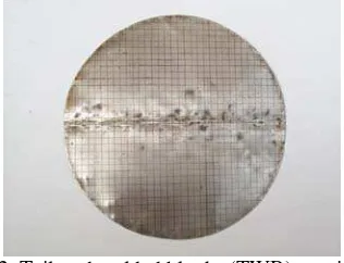
Fig 2. Tailored welded blanks (TWB) specimen
M-90
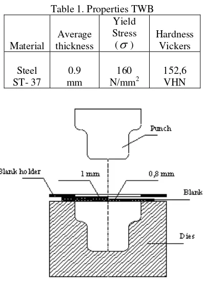
Table 1. Properties TWB
Material
Average thickness
Yield Stress (
σ
)Hardness Vickers
Steel ST- 37
0.9 mm
160 N/mm2
152,6 VHN
Fig. 3 Schematic of the deep drawing process of TWB
A clear view of the experimental tooling is shown in Fig 4. It corresponds to a single action drawing tool called as inverted dies with a draw cushion. The forming force is exerted by the slide above through the die and the blankholder onto the cushion in the press bed. The punch and the blankholder of the drawing tool are both located in a base plate on the press bed. Pressure pins, which come up through the press bed and the base plate, transfer the blankholder force from the draw cushion onto the blankholder. The female die and the blankholder are mounted on the press slide. At the start of the forming process the blank is held under pressure between the draw die and the blankholder. The slide of the press coming from the compression machine pushes the blankholder downward over the draw die – against the upward-acting force of the draw cushion. The part is formed via the downward movement of the die over the stationary draw punch. The press slide must apply both the pressing and the blank holder.
Fig. 4 Component of die set
Results and Discussions
M-91
three different views in order to clearly show the phenomena of crack happen in the weld line, weld movement, wrinkling occurring in the wall of both 0.8 mm and 2.0 mm thicknesses, and the wrinkling in the flange.
Fig. 5 Drawn parts of tailored welded blank
For the tailored blank that is subjected to uniform blankholder pressure, the blankholder force was seen to be not uniform. This can be simply explained as follows: since one of the sides of the blank is thinner than the other, we in fact have the effect of a non-uniform blankholder pressure distribution. Now taking a look at the tailored blank experiments more closely, we can see that the orientation or position of the tailored blank affects the outcome of the cup. In this experiment, it has been obtained that wrinkling has been appeared in the wall of 0.8 mm thickness. In contrast, there is no wrinkling that is created in the wall of 1.0 mm thickness. It has also been obviously seen that there are rigorous wrinkling of the flanges, and the frequency of wrinkles increases more in the thinner section of the blank. This is attributed to the fact that the blank is in a more non-uniform position considering the blank holder pressure applied. The non-uniform pressure from blankholder has product a clearance in the interface amongst blank, die, and blankholder surfaces. From fig. 4, it can also be seen that a crack or tearing failure occurs near the
Wrinkling in the wall of 0.8 mm thickness Crack in the
weld line
Weld line
No Wrinkling in the wall of 1.0 mm thickness
M-92
weld line on the cup wall. The reason of tearing can be addressed to the draw ratio of the blank and the formability of the HAZ and the weld line. The appearance of weld line, however, has decreased the formability of the blanks, resulting in crack failure.
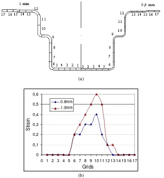
Strain distributions
For the evaluation of strain distribution on the drawn part of tailored blanks after deep drawing process, it was decided to measure the grid position lying in the mid of the blank. Since the blank is formed from two different thicknesses, the measurement is begun from the zero position value in the mid point of the cup, increases to the other side of the cup. The schematics of the measurement of the grid is shown in fig 6a. The measurement of grid position then is used to determine the strain distribution of the drawn part of tailored blanks, as shown in fig 6b.
(a)
Fig 6 (a). Grid positions in the sheets of 0.8 and 1.0 mm, (b) Strain distributions
The result of experiment has shown that, in general, all of the cups drawn gave evidence that the strain distribution in the direction of the ear is higher than that in the dip direction. This is quite logical in that in the ear direction we have more material because of anisotropic properties of the sheet metal. Cups drawn at applied non-uniform blankholder pressure were seen to have larger strains in the direction of the highest point of the force applied. This is due to the fact that the material is braked by the non-uniform blankholder distribution, resulting in the effect of a larger ear, caused not only by enhanced anisotropic properties but also by the effect of mechanical properties of the hydraulic press.
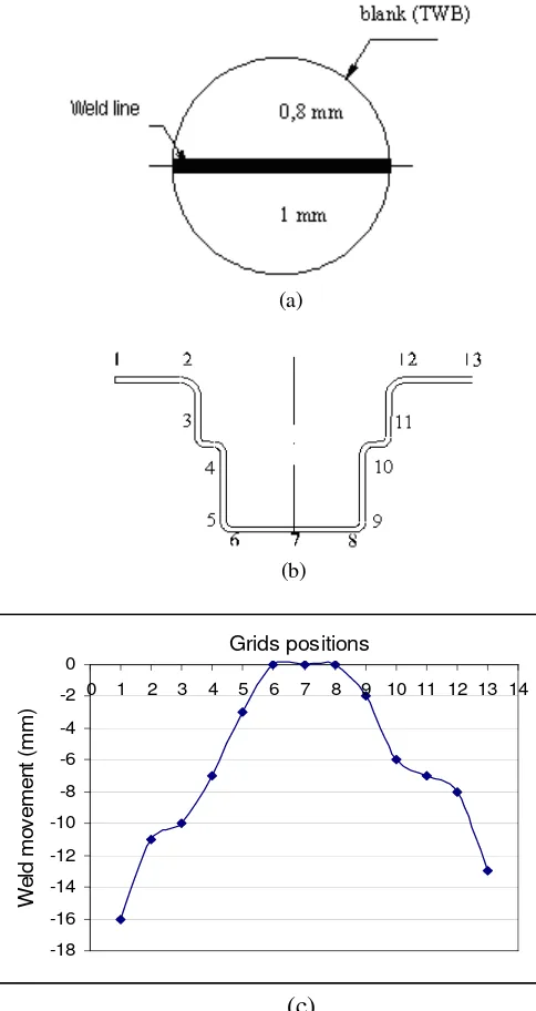
Weld movement
M-93
Fig. 7 (a). Two sheets of TWB, (b). Grid positions in the blank, (c). Weld movement
Conclusion
With respect to the tailored blank experiments, it was found that the placement of the blank in respect of a non-uniform blank holder pressure affects the quality of the drawn cup. It has been obtained rigorous wrinkling of the flanges, and the frequency of wrinkles increases more in the thinner section of the blank. All of the cups drawn gave evidence that the strain distribution in the direction of the ear is higher than that in the dip direction. It can also be clearly seen that the weld in the flange region moves towards the thicker base material.
References
Saunders F.I, Wagoner R.H., The use of tailor-welded blanks in automotive applications, in: S.-F. Shen, P.R. Dawson (Eds.), Simulation of Materials Processing: Theory, Methods and Applications, 1995, Balkema, Rotterdam, pp. 157-163.
M-94
Venkat, B. S., Albright, C. E., Ramasamy, S., and Hurley, J. P., (1997), “CO2 Laser Beam Welding of Aluminum 5754-O and 6111-T4 Alloys”, Welding Journal, Vol. 76, No. 7, July, pp. 275-82s.
Ahmetoglu, M. A., Brouwers, D., Shulkin, L., Taupin, L., Kinzel, G. L., and Altan, T., (1995), “Deep Drawing of Round Cups from Tailor-welded Blanks”, Journal of Material Processing Technology, Vol. 53, pp. 684-94.
Siegert, K., and Knabe, E., (1995), “Fundamental Research and Draw Die Concepts for Deep Drawing of Tailored Blanks”, SAE Transactions: Journal of Materials and Manufacturing, Vol. 104, pp. 866-76.
Shi M F, K.M. Pickett, K.K. Bhatt, SAE Paper 930278, Society of Automotive Engineers, 400 Commonwealth Drive, Warrendale, PA 15096-0001, 1993.