IEEE Student Conference on Research & Development 2013
Demonstration of Self-Powered Accelerometer Using
Piezoelectric Micro-Power Generator
Bong Yu Jing, Kok Swee Leong Member, IEEE
Faculty of Electronic and Computer Engineering Universiti Teknikal Malaysia Melaka
Hang Tuah Jaya, 76100 Durian Tunggal, Melaka, Malaysia
Abstract- This paper demonstrates the operation of a self-power
vibration measurement system. A piezoelectric material in the form of a cantilever is being used as a generator which harvest energy from ambient vibration source and transform into useful electrical output. The vibration sources is measured with a MEMS based accelerometer, which is powered up by the transformation of electrical energy derived from the mechanical vibration source itself. It has shown that at a resonant frequency of 78 Hz with an acceleration level of 1g (9.81 m/s2), the piezoelectric generator is able to produce rms output voltage of 5.20 V and successfully operating ADXL335 with the assistance of energy harvesting conditioning IC, LTC3588-1 equipped with rectifying as well as DC-to-DC step-down functions.
I. INTRODUCTION
Self-powered system is remarkable attractive for building a sustainable and environmental concern application to replay batteries, particularly those employ in a big number such as wireless sensor node in a wireless sensor network, which is able to be powered with low level electrical power [1].
Notably, vibration source is one of the common source uses to transform into useful electrical energy from ambient environment due to its availability in almost everywhere as long as there is moving mechanisms, as have been surveyed in [2] include those home appliances, industrial environment as well as human activities. Piezoelectric material in the form of a cantilever is one of the popular mechanisms used to transform vibration or kinetic energy into electrical energy based on direct piezoelectric effect. Maximum output power can be generated when the device is operated at its resonant frequency, however it has also shown the possibility to harvest multiple frequencies from vibration sources [3].
There have been quite a number of researches working toward self-power system as described by Chao P. [4], which operated for a long time on the same entities which can be embedded into structure or human bodies. The extension of the research has gone into maximizing the by using maximum power point tracking as described by Kong, N. [5]. The advancement of integrated circuit performance has also enabled self-power electronic system to be applicable for harvesting vibration energy in short duration as described in [6].
In this paper, the combination of piezoelectric generator and energy harvesting condition circuit are used to verify the functionality of self-power accelerometer in measuring acceleration level of a vibration source.
II. SELF-POWERED SYSTEM COMPONENTS
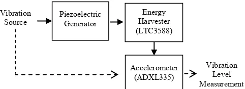
The system consists of Piezoelectric Generator, energy harvesting conditioning integrated circuit (LTC3588-1) from Linear Technology, Inc. and MEMS accelerometer, ADXL335 from Analog Devices, Inc. The connection is show in Fig.1 the block diagram of the overall system.
The block diagram of the system is shown in Fig. 1, where the vibration source will be transformed into alternating current (AC) voltage output. The AC voltage output will be converted to direct current (DC) by energy harvesting integrated circuit, LTC3588-1 and DC to DC step down before being used to power up accelerometer, ADXL335 for measuring the vibration amplitude.
Fig. 1. A block diagram of the self-power vibration measuring system. The bold arrow representing the energy flows whereas the dotted arrow
representing the signal flows.
The concern of the energy flows is the minimum requirement for powering the accelerometer. From the data sheet of ADXL335 [7], the operating voltage range is 1.8 V to 3.6 V. The output voltage from the energy harvesting conditioning integrated circuit, LTC3588-1 has to be set to operate in this range, it may not functioning properly if voltage level is lower than 1.8 V and may damage the accelerometer if voltage level greater than 3.6 V.
A. Piezoelectric Generator
IEEE Student Conference on Research & Development 2013
electrical load is connected to the terminal of the generator. The dimension of the Q220-A4-503YB piezoelectric generator is show in Fig.2 and its performance guideline is show in Table 1.
Fig. 2. Dimensions of the piezoelectric generator Q220-A4-503YB used in this project.
TABLE I
PERFORMANCE GUIDELINE OF PIEZOELECTRIC BENDING GENERATOR (Q220-A4-503YB)
Element Value
Piezo Material 5A4E
Weight (grams) 9.5
Stiffness (N/m) 2.4x10²
Capacitance (nF) 260
Rated Tip Deflection (mmpeak) ±1.57
Rated Frequency (Hz) 45
Open Circuit Voltage (Vpeak) ±18.1 Closed Circuit Current (µApeak/Hz) ±46 Rated Output Power (mWrms) 4.7
B. Energy Harvesting Conditioning Integrated Circuit
Piezoelectric energy harvesting conditioning integrated circuit being used in this project is LTC3588 from Linear Technologies, Inc. LTC3588-1 combines a low-loss full-wave bride rectifier and a high efficiency buck converter to create an energy harvesting devices optimized for large output impedance energy source. It is designed for energy harvesting that has ultra-low quiescent current (Iq) power supply. It can
be used by directly connecting it to the piezoelectric or AC power source. The LTC3588 will rectify the voltage waveform and store the harvested energy in the capacitor. Besides that, it can also cut off any excess power through its internal shunt regulator and maintain regulated output voltage by using nano power high efficiency synchronous buck regulator. Fig.3 shows the block diagram of LTC3588-1. The IC has selectable output voltages of 1.8V, 2.5V, 3.3V and 3.6V, depends on the configuration of the D1 and D0 pins with a range of voltage input threshold of 3.77V to 5.37V [9].
In this project, output voltage of 3.3V will be selected, as it falls in the middle of the range of operating voltage for ADXL. Whilst at the output voltage of 3.3V, the IC needs an
input range of 4.73V to 5.37V from the piezoelectric generator. The regulator start-up profile of the LTC3588-1 is shown in Fig. 4.
Fig. 3. Functional Block Diagram of LTC3588-1[9]
Fig. 4. LTC3588-1 regulator start-up profile [9].
C. MEMS Accelerometer (ADXL335)
ADXL335 is a low power 3-axis MEMS accelerometer, based on the principle of capacitive transduction. It can measure acceleration with minimum full-scale range of ±3g, the static acceleration of gravity, and the dynamic acceleration from shock, motion, or vibration. Besides that, it also produces signal conditioned voltage outputs. The block diagram of ADXL335 is show in Fig.5.
IEEE Student Conference on Research & Development 2013
III. EXPERIMENTAL SET-UP
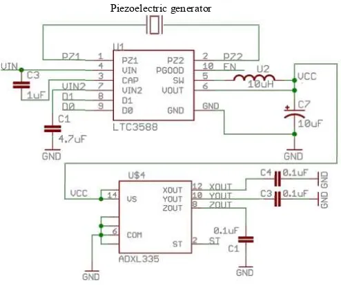
The self-powered acceleration measurement system consists of 3 parts as discussed in Fig. 1, is presented in schematic diagram as shown in Fig. 6.
Fig. 6. Schematic Diagram of the combined Circuit
Before the electronic system is connected, the mechanical resonance frequency of the piezoelectric generator is determined by excited with electrodynamic shaker at a range of frequency from 20 Hz to 100 Hz with acceleration level (g-level) set at a constant magnitude at 1-g (9.81 m/s2). The result obtained is as shown in Fig.7. The resonance frequency of the cantilever based piezoelectric generator with proof mass attached is at around 78 Hz with a bandwidth of 73Hz to 83Hz.
Throughout the experiment in the following section, the vibration source frequency is set at 78 Hz in order to generate maximum output voltage at its resonant.
0.0 1.0 2.0 3.0 4.0 5.0
20 40 60 80 100
V
o
lta
g
e,
V
rm
s
Frequency, Hz
Fig. 7. Frequency response of cantilever based piezoelectric generator at a constant acceleration level of 1-g (9.81 m/s2).
The g-level of the vibration source is measured with G-Link wireless accelerometer from LORD MicroStrain [10] and the data collected in time domain is processed using FFT in Matlab to present in frequency domain as shown in Fig. 8.
Fig. 8. Time and frequency domains of electrodynamic shaker vibration measurement data using G-link with
IV. EXPERIMENTAL RESULTS
The output from the piezoelectric generator is shown in Fig. 9 when being excited at the vibration source in Fig. 9. The result shows that piezoelectric generator produces AC voltage output at a peak-to-peak voltage of about 7.28V which derive Vrms value of 5.20V. This voltage value is too large to operate ADXL335 accelerometer which only support up to a maximum of 3.6V, hence step-down DC-to-DC converted is needed before supplying the voltage to the accelerometer. Besides that, accelerometer only support DC supply, hence the AC voltage from piezoelectric needed to be convert to DC first before feeding into the accelerometer.
Fig. 9. AC output voltage from piezoelectric generator when excited at 78 Hz with an amplitude of 1-g.
IEEE Student Conference on Research & Development 2013
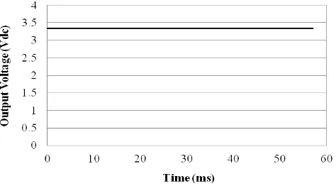
The output from the piezoelectric generator was fed directly to the PZ1 and PZ2 pin of the energy harvester IC, LTC3588-1. The DC voltage output of LTC3588 is shows in Fig. 10. The voltage produced and average value of Vdc 3.34V,
with maximum value of 3.52V and minimum value of 3.12V.
Fig. 10. Output voltage, Vdc from LTC3588.
The output voltage, Vdc from LTC3588-1 is then directly
fed into Vcc pin of ADXL335 to operate the accelerometer. The output of the accelerometer is compared with the measurement value using G-link wireless accelerometer. However, if the acceleration drops to 0.8g, the supply voltage will not able to power up the ADXL335, because the voltage produced by the piezoelectric generator during 0.8g is only 3.81V, which is lower than the minimum voltage input requirement of LTC3588-1.
Fig. 11. Comparison of self-powered and battery powered ADXL measurement output for different level of acceleration using G-link wireless accelerometer as the standard reference.
V. CONCLUSIONS
The paper has demonstrated the application of self-powered accelerometer measuring acceleration level of a vibration source. The self-power system is using the same mechanical vibration source to transform into electrical energy
to power up the accelerometer. The major concerns of designing a self-power system are the minimum and maximum power or voltage requirement of the operation. In this case the ADXL335 needs minimum DC voltage of 1.8 V to operate and voltage above 3.6 V will damage the device. As the voltage output of a piezoelectric generator can be varied in a big range in an AC form, therefore a rectifier and DC-to-DC step down circuit is important to ensure proper operation of the accelerometer. In order to provide such stable DC voltage, LTC3588-1 IC is being used. The experimental results verified the operation of the self-power system, whereby when acceleration fell to 0.8g, the output voltage from the piezoelectric generator, which is 3.81V, is not able to step-down to 3.3V using LTC3588-1 and hence ADXL335 was not able to function properly.
ACKNOWLEDGMENT
The authors would like to thank the Ministry of Higher Education for the research grant, PRGS/2011/FKEKK/TK02/1
– T00001, as well as Universiti Teknikal Malaysia Melaka for CoE short term research grant PJP/2012/CeTRI/Y00001, Advanced Sensors and Embedded Control Research Group, Centre for Telecommunication Research and Innovation for supporting the research and sponsoring the presentation of this article.
REFERENCES
[1] J.H. Jang, D.F. Berdy, J. Lee, D. Peroulis, and B. Jung, "A wireless condition monitoring system powered by a sub-100 W vibration energy harvester", IEEE Trans. on Circuits and Systems, Vol. 60(4), pp. 1082-1093, April 2013.
[2] M.F. Ab Rahman and S.-L. Kok, "Investigation of useful ambient vibration sources for the application of energy harvesting", IEEE Student Conference on Research and Development (SCOReD), pp. 391-396, 2011.
[3] S.-L. Kok, N. Mohamad, D.F.W. Yap, S.K. Chen and C.F. Dee."Multi-frequency energy harvesting using thick-film piezoelectric cantilever", Int. Conf. on Electrical, Control and Computer Engineering(INECCE), pp. 420-423, 2011.
[4] P.C.-P, Chao., “Energy harvesting electronics for vibratory devices in self-powered sensors". IEEE Sensors Journal, Vol. 11 (12), pp. 3106– 3121, Dec 2011.
[5] N, Kong, and D.S. Ha, “Low-power design of a self-powered piezoelectric energy harvesting system with maximum power point tracking”, IEEE Transactions on Power Electronics, Vol. 27(5), pp. 2298-2308, May 2012.
[6] I.M. Darmayuda, Y. Guo, M.T. Tan, S.-J. Cheng, Y. Zhen, M. Je and C.-H. Heng, “A self-powered power conditioning IC for piezoelectric energy harvesting from short-duration vibrations”, IEEE Transactions on Circuits and Systems, Vol. 59 (9), pp. 578-582, 2012.
[7] ADXL335 data sheet, http://www.analog.com/en/mems-sensors/mems-inertial-sensors/adxl335/products/product.html (accessed on 1st
September 2013).
[8] Piezo System, Inc http://www.piezo.com/prodbg7qm.html (accessed on 1st September 2013).
[9] Linear Technology, Inc, http://www.linear.com/product/LTC3588-1
(accessed on 1st September 2013).
![Fig. 3. Functional Block Diagram of LTC3588-1[9]](https://thumb-ap.123doks.com/thumbv2/123dok/534036.61916/2.612.364.515.286.442/fig-functional-block-diagram-ltc.webp)