Free-Standing Pb(Zr, Ti)O
3Thick-Films Prepared By a One-Step Air
Co-Firing Technique
Swee L. Kok, Neil M. White and Nick R. Harris
School of Electronics and Computer Science, University of Southampton, Southampton SO17 1BJ, UK
Corresponding author email: [email protected]
Abstract
Combinations of conventional thick-film technology and sacrificial layer techniques were used to fabricate free-standing structures, in the form of cantilever beams. By taking advantage of the different thermal expansion coefficients between silver/palladium (Ag/Pd) and piezoceramic Pb(Zr, Ti)O3, it was possible to fabricate a flat, but angled cantilever. In this
work, sandwich structures consisting of PZT layers and Ag/Pd conductors, with in either interdigitated (IDT) or plated electrode configurations were fabricated in order to investigate the structural strength and the characteristics of free-standing structures. Screen printed carbon was used as a sacrificial layer. In the final step of the process, this was burnt out at a temperature of 850 C in an air environment. This resulted in a free-standing, sandwich structure of PZT-Ag/Pd. In order to reduce the problems of process complexity, a one-step firing process was used, whereby the sacrificial layer was co-fired together with PZT-Ag/Pd layers. The measurement results showed that the materials have a piezoelectric charge coefficient, d31 of -25 10-12 C/N and coupling coefficient, k31 of 0.125. The cantilever
structures were found to have a maximum Q-factor of around 200, and produced useful amounts of electrical power when driving resistive loads at low acceleration levels.
Keywords: Films; Composites; Piezoelectric properties; PZT; Free-standing structure
Introduction
Micro-scale free-standing structures have been fabricated with a combination of thin-film and silicon micromachining technologies [1]. Thick-film technology, however, has not received significant attention compared with its competitor technologies, for fabricating free-standing structures. One of the main reasons for this is because piezoceramics are considered too fragile to form free-standing structures. Circular membranes (a form of free-standing structure), fabricated with thick-film technology for use as pressure sensor, were possibly the first of this kind to be reported [2].
In this paper, thick-film free-standing structures were fabricated into a multilayer of PZT piezoceramic and Ag/Pd conductor, by using combination of conventional thick-film technology and sacrificial layer technique. This fabrication method involves co-firing the composite layers together in air to burn out carbon sacrificial layer and releasing a free-standing structure above the substrate, in a form of cantilever. This one-step air co-firing technique is simple and does not involve any chemical for etching the sacrificial layer as found in thin-film and micromachining processes. Interdigitated (IDT) (operated in d33 mode:
mode: stress is applied perpendicular to the polarization direction) were fabricated to investigate the role of the materials in sustaining the free-standing structures and also to compare the electrical output power.
Conventionally, thick-film piezoelectric materials were printed directly on substrate, which was rigidly clamped on substrate, therefore influences the piezoelectric properties of the materials [3]. In the form of free-standing structures, the clamping effect on thin electrodes is minimal, hence, the mechanical and electrical properties of the piezoelectric materials e.g. piezoelectric constants, coupling factor and elastic constant, can be measured accurately with a resonant measurement method. In the development of cantilevers as microelectromechanical systems, measurement of the Q-factor is also an important characteristic in determining the dynamic performance of the system. In a series of experiments, the Q-factor was measured for samples with fixed widths but different lengths.
Resonant Measurement Method
The resonant measurement method is one example of a dynamic method commonly used to determine the piezoelectric and elastic properties, as suggested by Mason and Jaffe [4]. This technique involves the measurement of the resonant and antiresonant frequencies of a piezoelectric material. Since these frequencies can be accurately measured, this method provides a good basis for determining the properties of piezoelectric materials.
The coupling factor of piezoelectric materials can be obtained by measuring the resonant
The piezoelectric charge coefficient, d31 (C/N) is one of the key parameters, which indicates
the piezoelectric activity of the materials. It is related to the coupling factor, k31, by the
following equation [5],
d31 k31 33Ts11E . (2)
where 33T is the permittivity of the piezoelectric material (F/m), which is related to the
capacitance CT (at constant or no stress) , thickness, h and the area, A of the material,
One-Step Air Co-Firing Fabrication Steps
Typical piezoceramic thick-film fabrication steps are conducted in sequence starting with paste composition, screen-printing deposition, drying and co-firing and finally polarization of the film. Some of the main issues for piezoelectric thick-film fabrication are the production of films that are uniform in thickness, crack-free, have high mechanical density, reproducibility, and good piezoelectric performance.
Reproducibility and good piezoelectric performance can be achieved by formulating optimized paste composition. The curing or co-firing temperature is crucial in determining the piezoelectric properties of the films, while screen-printing with correct pressure and snap-gap can control the film thickness and uniformity. The screen mesh and emulsion thickness are also important for controlling the film resolution and ensuring high quality prints.
The functional element of the structures, PZT piezoceramics, was formulated from mixing Pz29 powder (Ferroperm Piezoceramics Ltd.) with particle sizes of 0.8 and 2 m in a ratio of 1:4, 10 % by weight of lead borosilicate glass (Ferroperm CF7575) and appropriate amount of vehicle (ESL 400) to make screen printable paste [6]. The carbon paste, similar to that described by Birol et al [7], was made by mixing graphite (Sigma-Aldrich 282863) with the organic binder ethyl cellulose (Sigma-Aldrich 433837) in a ratio of 1:3. Ethyl cellulose was dissolved in terpineol (Fluka 86480) in advance before mixing with graphite and acetyl acetone together to reduce the paste viscosity. Both pastes were homogenized by using a triple-roll mill before screen printing on an alumina substrate. The properties of Ag/Pd paste (ESL 9633B) which include high conductivity, low electromigration and good solder leach resistance, are suitable for use as lower and upper electrodes of the sandwich structure. Metals have higher tensile strength and higher thermal conductivity compared to brittle ceramics and are therefore useful as the supportive layer for the composite structure. However, Ag/Pd conductor has higher thermal expansion coefficient compared to the piezoceramic, and therefore tends to peel off when exposed to drastic temperature changes during the firing process. This effect can be minimized by ‘protecting’ (covering) them with low thermal expansion ceramic materials.
The fabrication process commenced by screen printing the carbon sacrificial layer. Ag/Pd was then printed over the sacrificial layer to act as a lower electrode (and also as supporting structure). This step was followed by printing a few layers of PZT to achieve desired thickness, on top of the lower electrode layer. Finally another Ag/Pd layer was printed as the top electrode. Each printed layer was dried in an infra-red dryer at 140 C for 10 minutes, before successive layers were printed on top. The complete printed and dried layers were then fired together in an eight-zone belt furnace, using a sintering profile with a peak temperature of 850 C (held for 10 minutes). This results in a total firing time of around one hour. During the firing process, the organic binder in the sacrificial layer was burnt off and therefore the sandwich layer of electrode-PZT-electrode breaks free from the surface and begins to either bend inward or outward from the substrate because of the different thermal expansion coefficients between PZT ceramic and Ag/Pd. The graphite, which acted as filler in the sacrificial layer, was then burnt off totally in air as CO2 before the PZT ceramic was sintered.
involved adding extra layers of piezoceramic and Ag/Pd as the protective layers and supportive layers respectively to the original functional layer.
Fabrication Results and Discussion
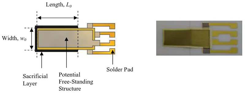
Due to the effect of having different thermal expansion coefficients, the composite structure was elevated (after the carbon sacrificial layer was burnt out) and bent away or towards the substrate depending on the material printing arrangement of the layers between the Ag/Pd conductor and piezoceramic. The fabricated free-standing composite cantilevers were found to shrink by 10 % from their original design dimensions as shown in Fig.1.
Fig.1. The outcome of a fabricated sample compare to the original design.
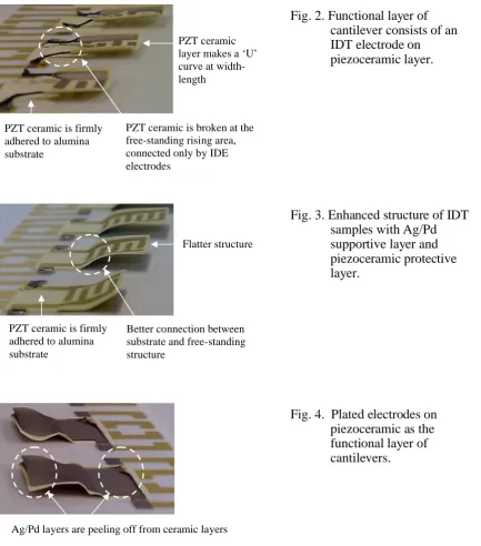
For samples with IDT electrodes printed on seven layers of piezoceramic, the structures were found to be curved across the width of the beams making a ‘U’ shape. The piezoceramic area, which was not covered by the conductor broke off and was supported only by the thin arm of the IDT electrodes, as shown in Fig.2. This shows that, Ag/Pd is a good supporting layer to the structure. By printing a combination of layers of ceramic-metal prior to the functional layer and another additional ceramic layer on top of the functional layer, the free-standing IDT cantilever structures were found to be stronger and flatter as shown in Fig.3.
The peeling off effect is clearly shown in the plated electrode samples (Fig.4). Because the rate of expansion and contraction of metals is greater than that of ceramics, the Ag/Pd electrodes of the functional layer were seen to be pulled away from the piezoceramic layer and create a wave-like structure. Using the enhancement method of additional protective layers of ceramic on both the upper and lower electrodes, smoother and flatter cantilevers were produced as shown in Fig.5.
Potential Free-Standing Structure Length, L0
Width, w0
Solder Pad Sacrificial
PZT ceramic is broken at the free-standing rising area, connected only by IDE electrodes
PZT ceramic is firmly adhered to alumina substrate
PZT ceramic layer makes a ‘U’ curve at width-length
Better connection between substrate and free-standing structure
Flatter structure
PZT ceramic is firmly adhered to alumina substrate
Ag/Pd layers are peeling off from ceramic layers
Fig. 2. Functional layer of cantilever consists of an IDT electrode on piezoceramic layer.
Fig. 3. Enhanced structure of IDT samples with Ag/Pd supportive layer and piezoceramic protective layer.
Flatter free-standing structure
Ceramic is adhered firmly to the substrate
Fig. 4. Plated electrodes on piezoceramic as the functional layer of cantilevers.
Measurement Results and Discussion
The electrical and mechanical properties of samples of cantilevers with plated electrodes, having a width of 9 mm and varying lengths from 4.5 mm to 18 mm, were measured using an impedance analyzer (HP 4195A). The structures were also characterised on a shaker table excited with sinusoidal vibrations over a range of different frequencies, around the resonant frequency of the beam. The acceleration of the shaker table was maintained at a constant level by using a PID control system. The output voltage from the samples was then driven into a programmable resistance load and subsequently converted to a digital signal and was measured with National Instrument Sequence Test programme.
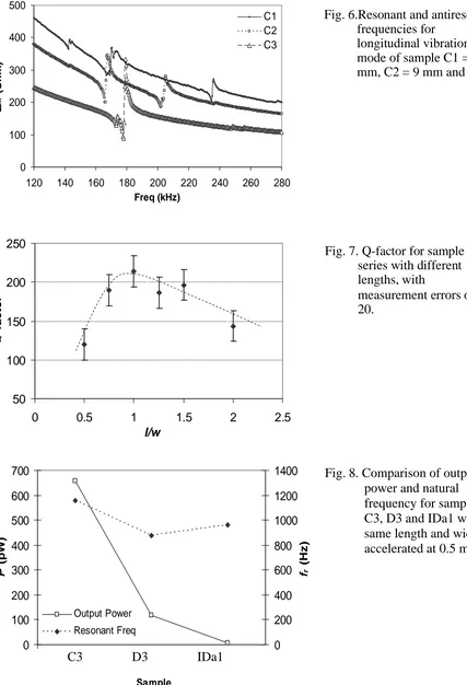
The resonant and antiresonant frequencies of the longitudinal mode depend on the length of the material. Fig.6 shows sample C1 = 6.75 mm, C2 = 9 mm and C3 = 13.5 mm having measured resonant frequencies of 178 kHz, 202.4 kHz and 234.8 kHz respectively. The capacitance of the material was proportional to the length of the material, which was measured at 3.3 nF, 4 nF and 6 nF for sample C1, C2 and C3 respectively. From equations (1) to (4), the piezoelectric charge coefficient, d31 was measured at -25 10-12 C/N, coupling
coefficient, k31 = 0.125, and constant electric field elastic compliance, S11E = 10 10-12 m2/N.
The Q-factor of the cantilever was found to be non-linear with increasing structure lengths. Fig.7 shows that the Q- factor increases from about 120 for the shortest sample to 210 for a square sample. Further increments of cantilever length then decrease the value of Q-factor. At a length of 18 mm, the Q-factor reduced to about 150. This is because, a shorter cantilever, with length smaller than the width, suffers from support damping loss while longer cantilever suffer from air damping loss as suggested by Jingling et al [8]. The design of cantilevers with different Q-factors depends on the specific nature of the desired application. For applications that require narrow-band frequency operation, square dimensions with high Q-factors are appropriate. However, a longer cantilever beam is desirable for vibration energy harvester. Longer beams are bent more, therefore exerting more stress on the piezoelectric material, hence producing more electrical energy compared to shorter structures.
In another experiment to compare the electrical output power, plated electrode sample, D3 having length, width and functional layer thickness similar to C3, but a slightly thinner non-active layer, was found to resonate at a lower frequency (875 Hz) compared to C2 (printed with two layer of ceramic) at 1155 Hz. Samples C2 and D3 were polarised at 2.5 MV/m and were found to produce an electric power output of 656 pW and 118 pW when driving into resistive loads of 29.5 k and 27.5 k respectively.
Theoretically, an IDT electrode beam operating in d33 mode produces more output voltage
compared to plated electrode beams operating in d31mode. This is because the output voltage
0
120 140 160 180 200 220 240 260 280 Freq (kHz)
Conclusions
Thick-film PZT piezoceramic and Ag/Pd conductor have provided a good combination of materials for fabricating composite piezoceramic free-standing cantilevers using a one-step air co-firing technique. Besides being a functional element, the piezoceramics act as a protective layer to compensate for the high thermal expansion of the conductors. The metal layers provide support for the brittle ceramics in upholding the free-standing structures. The electrical and mechanical properties of the free-standing piezoelectric material were measured, without being constrained to the substrate, thereby providing an accurate measurement. The maximum value of Q-factor of the free-standing structure was found to be 210. This was measured on a square-shaped cantilever. Samples having higher resonant frequencies were found to produce more electrical output power compared to samples with lower resonant frequencies, but having similar dimensions and slightly different thicknesses of the non-active layer. The output power of IDT electrode samples can be improved by using greater polarization voltages. In addition to operating as sensors and actuators, the piezoceramic free-standing structures have the potential to be used as micro-generators for powering various microelectronic devices.
Acknowledgements
A scholarship for the Phd study from Universiti Teknikal Malaysia Melaka is gratefully acknowledged.
References
1. Beeby, S. P., Ross, N. and White, N. M., Thick film PZT/micromachined silicon accelerometer. Electronics Letters, 35[23] 2060-2062 (1999)
2. Stecher, G., Free supporting structures in thick-film technology: A substrate integrated pressure sensor. 6th European Microelectronics Conferences, Bournemouth, pp. 421-427 (1987)
3. Steinhausen, R., Hauke, T., Seifert, W., Mueller, V., Beige, H., Seifert, S., et al., Clamping of piezoelectric thin films on metallic substrates: influence on the effective piezoelectric modulus d33. ISAF 98, Proc. of the 11th IEEE International Symposium on
Applications of Ferroelectrics, pp. 93-96 (1998)
4. Mason, W. P. and Jaffe, H., Methods for measuring piezoelectric, elastic, and dielectric coefficients of crystals and ceramics. Proc. Of the IRE, 42[6] 921-930 (1954)
5. Berlincourt, D., Curran, D. R. and Jaffe, H., Piezoelectric and piezomagnetic material and their function in transducers. In: Mason, W. P, editor. Physical Acoustics – Principles and Methods. Academic Press, New York, 1964, pp. 169-270.
6. Torah, R., Optimisation of the piezoelectric properties of thick-film piezoceramic devices. PhD thesis, University of Southampton, 2004.
7. Birol, H., Maeder, T., Jacq, C., Straessler, S. and Ryser, P., Fabrication of low-temperature co-fired ceramics micro-fluidic devices using sacrificial carbon layers. Int. J. Appl. Ceram. Technol., 2 [5] 364-373 (2005)