The 5
PSU-UNS International Conference on Engineering and
Technology (ICET-2011), Phuket, May 2-3, 2011
Prince of Songkla University, Faculty of Engineering
Hat Yai, Songkhla, Thailand 90112
Abstract: This paper presents a study on the
load-compression and energy absorption characteristics of a laterally crushed across faces of hexagonal ring with constraints on expansion perpendicular to the loading axis. The theoretical analysis in compression across faces is developed using Equivalent Structure Technique. Experimental observations are compared with theoretical analyses and good agreements are seen.
Keywords: Hexagonal ring, energy absorption, finite element analysis
1. INTRODUCTION
Much research and development has taken place in the area of impact energy absorbers. The energy absorption capacity of a circular ring under lateral compression was first addressed by Mutchler [1]. Two different kinematically admissible collapse mechanisms which result in same post-collapse load-deflection characteristic when employing a rigid perfectly-plastic material model were put forward by DeRuntz and Hodge [2] and Burton and Craig [3]. Careful and exhaustive experiments on the crushing of tubes and rings [4] led to the formation of a model that is based on the classical elastica theory that used a rigid linear strain hardening material behaviour [5]. However, by preventing the horizontal diameter of the ring from increasing, the formation of more plastic hinges is required. Reddy and Reid [6] examined the behaviour of laterally compressed tubes under transverse constraints and noticed that the collapse load increased by a factor approximately 2.4 and the energy absorbed increased by a factor of 3 in comparison with transversely unrestrained tubes. An excellent review of the energy absorbing systems, which use the lateral compression of metal tubes is given by Reid [7,8]. While, Leu [9] simulated aluminium tube under lateral compression using finite element modelling.
Plastic collapse of square tubes compressed laterally between two plates was studied by Sinha and Chitkara [10] who produced plastic collapse mechanisms. Gupta
and Ray [11] have performed experiments on thin-walled empty and filled square tubes laterally compressed by using a rigid platen. They analysed the problem with the Sinha and Chitkara [10] mechanisms and assumed plastic hinges occurred only at mid section of vertical side, while in horizontal side to be elastic bending. These analyses used plastic hinges and could be modified by replacing plastic hinges with plastic zones [12]. Johnson and Reid [13] cited the energy absorbing devices with hexagonal shapes referring to an article of Fuse and Fukuda [14] where in hexagonal tubes under quasi-static compression across faces were studied. The mechanism of collapse has hinges at the side corners and at the centres of loaded faces. Recently, Said and Reddy [15] developed a predicted load-displacement curve using upperbound analysis and found that the collapse load is in good agreement with experiment but deviate 20% - 25% after the post collapse.
In the present study, theoretical study has been given on a single hexagonal ring with side constraints subjected to compression across faces, by using equivalent structure technique [16]. The experimental results on the load-displacement are also compared. is developed and compared with experimental results [17,18].
2. ANALYSIS OF COMPRESSION A CROSS FACES WITH SIDE CONSTRAINTS
The Equivalent Structure Technique demonstrated successfully by Gill [16] and are used by Reddy and Reid [6] for a circular ring compressed diametrically with transverse constraints, is used. Owing to symmetry, only one half of the ring is considered. Friction between the tube and top and bottom platens is neglected. The material of the tube is assumed to be rigid-perfectly plastic and any interactions between bending and normal or shear stress resultants are neglected. The material is made of mild steel. Modulus of Elasticity, E is 212 GPa. The yield stress, y and poisson ratio, v is 212 GPa and 0.27, respectively.
Figure 1 shows two possible modes of deformation for one half of a hexagonal ring compressed vertically
THEORETICAL ANALYSIS OF
QUASI-STATIC COMPRESSION OF
HEXAGONAL RING
M.R. Said
1*and A. S Tahir
1 1Faculty of Mechanical Engineering, Universiti Teknikal Malaysia Melaka, MalaysiaFigure 4.6
''
Dotted and broken lines indicate the initial configuration and the starting positions for
"
Mp resultant force
line of '''
Mp Mp
Mp
D D
Crushing across the faces of a tranversely constrained hexagonal ring. (a) undeformed (b), (c), and (d) show different phases during deformation.
(continued) : (c) Phase 2 (ii) mode 2
F/2
F B
(d) Phase 3
F/2
F B
line of resultant force
G'' '' C
Q'' N'' E''
I'' '' H
O
b/2
M o
F/2
''
F/2
y''' J''' C
I''' x'''
Q'''
''' E''' x'''
''' A''' A'' O G''' b/2
b/2 M'''
across faces and restrained laterally. There are three distinct phases in each mode. In mode 1, the link
AGE
is assumed as a rigid in all three phase, while in mode 2,AGE
remains rigid only in phase 1 andGEC
is assumed to be a rigid link in phase 2 and 3. However, mode 1 shows close correlation with the experimental observation[18]. Thus, the analysis is based on mode 1.
Figure 1: The possibility of deforming mode of hexagonal ring, compressed across faces: mode 1 and mode 2
Crushing across the faces of a transversely constrained hexagonal ring.
Dotted and broken lines indicate the initial configuration and the starting positions for (a) undeformed (b), (c), and (d) show different phases during deformation.
Mp
F/2
Mp
resultant force
Mp
,R
D
the respective phases (continued). (a)
Figure 8 : resultant forceline of
F B
,R F/2
(b) Phase 1
F D
B C
E
x' A
G
b/2 C Q'
E'
G'
O A'
N' x' H' J' I' o
line of
y' A G M'
F/2
b/2
Mp
(c) Phase 2 (i) Mode 1
D
F B
y'' " x'' I'' Q'' " C
N'' " E''
x'' J'' H''n b/2G''
A''
O "
A' o
b/2
F/2
M''
The bottom half remains rigid in all three phases. The first phase starts with the formation of 3 hinges at
' ' '
,
, and
.
A E
C
The load acts at pointsG
,A
movesdown and moves in vertical with
E
' as centre. This continues until the two hingesA
'andE
' at the same horizontal level as shown by the broken lines in Figure 2c. Further deformation proceeds (in phase 2, mode 1)with the stationary hinge
A
" moving down, the geometry compatibility being facilitated by the reversal of the direction of rotation about C. This continues until"
A
is the same level withC
. The third phase is shownin Figure 2d. The phase ends as link
CE
becomes horizontal.2.1. Analysis of Phase 1
Figure 2b shows a general position in phase 1. The load is acting at
G
and the position is defined by a deflection, δ.A G E
remains rigid and the links rotate at about plastic hinges atA E
,
andC
.AE
inclinedat 30° to the horizontal before deformation (i.e αo= 30°), is now inclined at an angle γ. If
I
is the point of intersection of vertical line throughG
and the horizontal line throughA
, the line of action of the resultant force,R
is parallel toCI
. The equivalentstructure for
CE G
should be parallel to the line of action of the resultant force and equidistant fromC
andE
, causing fully plastic moments (
Mp = ) at these points. The horizontal component of this resultant force with a moment armI J
will be responsible for the plastic bending moment atA
. The bending moment atA
is also can be checked and equal to Mp. The horizontal component ofR
is H = R cos and this acts with a moment army
=I
J
=x
/cosand hence themoment at
A
is Hy
= Rx
= Mp.The various angles defining the geometry at the instant shown are given in Figure 2b.
CI
and hence the line of action of the resultant force is inclined at an angle to the horizontal. For a given leads to the displacement of,
' ' ' ' ' ' ' (1)
M N G T H I H N
where
' ' sin
' ' sin( ); ' '
2 2
' ' cos sin ; ' ' cos o
o
o o
M N b
b b
G I G A
H I b E A b
and
' ' ' ' sin
2 b H N E Q
Therefore,
sin sin( ) cos sin sin
2 2
o o o
b b
b b
(2)
It can be shown from geometry that
and
arerelated by
CQ
Q O
CO
as Figure 2 : Crushing across the faces of a transverselycos 2 cos cos
2 2
cos
2
1 2 cos 2 cos cos (3)
o o
o o
b b
b
b
The resultant force to cause fully plastic bending moments at
C
andE
is'
p
M
R
x
because sin and 2 '' sin , then (4)
2 2
8 sin
(5) sin
p
F b
R x
M F
b
cos sin sin
' ' 2
where and tan (6)
' '
cos( )
2 o
o b b
I N
b C N
b
Phase 1 ends when hinges
E
andA
at the same horizontal level, i.e. = 0°. At this instant, noting that= 40.35°, it can be seen that = 34.11° and this = 74.46° from equation (6). The deflection, at the end of phase 1 obtained from equation (2) is 0.1343b as α o = 30° and o = 60°.
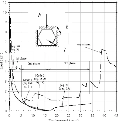
The load-deflection trace represented by equations 2 and 5 is shown in Figure 3. The experimental load-deflection curves are also compared [18].
2.2 Phase 2- Mode 1
Figure 2c(i) shows the mode of deformation in phase 2. The hinge
A
continues to move down along the vertical line, toA
,A G E
remains rigid whileCE
rotates about hingeC
. In this phase,E
will be the instantaneous centre of rotation ofA G E
. The end of this mode of deformation occurs when,A
is at the same level asC
. The line of resultant force is parallel toCI
and is equidistant fromC
andE
.'' '' '' '' '' '' (7)
sin sin( '') sin '' (8)
2 2
o o
M N G H H N
b b
b
It can be shown from geometry that
and
arerelated by
C
Q
Q
O
CO
, ascos cos cos ''
2 cos ''
2
1 2 cos 2 cos cos '' (9) o o
o o b
b b
b
The resultant forces and resisting moment are related
by,
x
M
R
p
and the applied and resultant forces bysin '' (10) 2
hence,
8 sin ''
(11) sin ''
where as bef p F
R
M F
b
ore 2 ''
sin '' ; '' '' '' and (12)
2
'' '' '' '' '' ''
tan ''
'' '' '' ''
sin '' sin( '') sin( '')
2 2 2
cos '' cos( '')
2 2
o o
o x
b
I N H N H I
C N C N
b b b
b b
(13)
End of phase 2 is when point
A
andC
are at thesame level. At this instant
30
o,
=0o,
60
o and = 0.43b. The bending moment atA
can also be checked and found to be equal to Mp during this phase. The horizontal component ofR
is R
cos
acts with a moment arm
I
J
x
cos
y
and hence the moment atA
is Mp. It also can be shown that bending moment at
G
is always less than Mp as distancen
is always less thanx
.The load-deflection curve represented by equations 8 and 11 is plotted in Figure 3.
2.3 Phase 2- Mode 2
In an alternative mode, as shown in Figure 2c(ii), point
G
travels downward and a plastic hinge is formed atG
. The linkE G C
is assumed to be rigid (henceo o
22
.
22
as at the end of phase 1) until hingeA
is the same level with hingeC
.'' '' '' '' (14) where,
'' '' sin
'' '' ''sin( '' ); '' 2 cos 2 o
o o
M N G N
M N b
b
G N CG CG
Therefore,
sin o sin cos osin( '' o) (15) b
It can be shown from the triangle
CG I
that cos'' '' sin( '' '') (16)
sin(90 '')
o
o b
G I
The resulting force to cause fully plastic bending at
C
and
G
is(17) ''
p
M R
x
We have as before
cos
) 90 sin(
sin cos cos
I G 2 and sin 2
o o
b x
R F
……….(18)
Combining equations (17) and (18) give
)
sin(
cos
sin
4
o o
p
b
M
F
(19)Mode 2 in phase 2 terminates at
b
o
41
.
0
and
52
,
0
. The bendingmoment at is found to be Mp.
The load-displacement of equations 15 and 19 is plotted in Figure 3.
2.4 Phase 3
This phase starts with hinge
A
at pointO
and at the same level with hingeC
. At this instant, the point of load application F/2 has shifted to pointE
which as shown in Figure 3. The linkA G E
is assumed to remain rigid and hingeA
continues to move down along the vertical line facilitated by rotation aboutC
and
E
. This phase continues untilCE
becomes horizontal. For a given
leads to the displacement, of,''' ''' ''' '''
sin sin ''' (20) 2
o
M N E Q
b b
Now,
x
M
R
R
F
p
2
sin
,
(21) where,2
x
E I
cos
,as
E I
A E
sin
;
A E
b
cos
o
can be obtained from the condition,b
CO
CQ
A I
as
2
cos
1
cos
1
cos
o
(22)
can be obtained from the compatibility ofQ I
tan
Q I
E I
E Q
CQ
CQ
where,
sin , sin cos
2 2
b b
E I A E
EQ
and CQ
then,
0
2 cos
sin
sin
tan
cos
Hence,
sin
sin
8
b
M
F
p (25)End of phase 3 is when
CE
becomes horizontal,i.e.
0
. At this instant,
54
.
7
o,
54
.
7
oand
0
.
866
b
. The horizontal component of resultant force is Rcos
acts with a moment arm
I
J
x
/
cos
y
and hence the momentat
A
is Mp.The load-deflection curves of the third phase in equations 20 and 25 are plotted in Figure 3.
3 DISCUSSION
The analysis in section 2 is an idealisation of reality. The aspects not included in the analysis are friction, interaction of bending and normal or shear stress resultants, aspect of material properties, dimensional variations and at the corners initially during deformation at plastic zones. This gives a slight deviation on
displacement curve compared with the experimental result. It also assumes that the deforming mode is symmetrical about the vertical axis but in experiment this is not observed. Figure 3 shows the comparison between analyses and experimental results on load-displacement curve compressed across faces. The predicted collapse loads are infinite as moment arms are zero in the idealised cases (phase 1 in Figure 3). The zero load observed in the analysis is due to the fact that the line of action of the resultant force becomes horizontal and hence the vertical component is zero (end of second phase in Figure 3). The predicted load-displacement curves in the first phase for the case of compressed across faces seem to have the same form as the experimental curve (Figure 3) in which the load drops very fast within 5 mm displacement.
Figure 3:Comparison between analytical and experiment load-displacement curve for lateral compression hexagonal rings across faces with side constraints (b = 40mm, t = 1.87mm, w = 10mm)
However, the theoretical valley load underestimates the experiments up to 50% in compression across faces. This could be due to the effect of changes in the geometry resulting from strain hardening and neglect of the interaction of bending, normal and shear stress resultants in the analysis. The neglect of frictional effects in the analysis between the side constraints and ring faces also contributes to the differences between theory and experiment in the appropriate post collapse regimes. In addition, the analysis assumes symmetrical deformations, but the lack of symmetry in experiment is obvious particularly in the later stages.
4 CONCLUSION
The theoretical analysis produces good results in phase 1 when compressed across faces. If friction and strain hardening effects are introduced in the analysis, the result may be close to experiment.
5 REFERENCES
[1] Mutchler, L. D., Energy absorption in aluminium tubing. J. Applied Mech, 27, 1960,pp. 740-743.
[2] DeRuntz & Hodge., Crushing of a tube between rigid plates. J. Applied. Mech, 30,1963, pp. 391-395 [3] Burton, R. H., & Craig, J. M., An investigation into
the energy absorbing properties of metal tubes loaded in the transverse direction. B.Sc. Report, University of Bristol, 1963.
[4] Reddy, T.Y., & Reid, S.R., Phenomena associated with the crushing of metal tubes between rigid plates. Int. J. Solids and Structures, 16, 1980, pp.545,
[5] Reid, S.R., & Reddy, T.Y., Effect of strain hardening on the lateral compression of tubes between rigid plates. Int. J. Solid and Structures, 14, 1978,pp. 213-225
[6] Reddy, T.Y., & Reid, S.R., Lateral compression of tubes and tube-systems with side constraints. Int. J Mech. Sci, 21, 1979,pp. 187-199
[7] Reid, S.R., Laterally compressed metal tubes as impact energy absorber. In: Jones N. and Wierzbicki T. Editors. Structural Crashworthiness, Butterworth, 1983,pp. 1-43
[8] Reid, S.R., Metal tubes as impact absorbers. In: Reid S. R. Editor. Metal Forming and Impact Mechanics, Pergamon Press, 1985,pp 249-269
[9] Leu, D.K., Finite-element simulation of lateral compression of aluminium tube between rigid plates. lnt J Mech Sci, 41, 1990,pp. 621-638
[10]Sinha, D.K., & Chitkara, N.R., Plastic collapse of square rings. Int. J. Solid Structure, 18(18), 1982,pp. 819-826
[11]Gupta, N. K., & Ray, P., Collapse of thin-walled empty and filled square tubes under lateral loading between rigid plates. Int J Crashworthiness, 3(3), 1998,pp. 265-285
[12]Reddy, T.Y., Impact energy absorption using laterally compressed metal tubes. PhD Thesis, Depart of Eng, University of Cambridge, England, 1978.
[13]Johnson, W., & Reid, S. R., Metallic Energy Dissipating Systems. Applied Mechanics Reviews, 31(3), 1978,pp. 277-288
[14]Fuse, H., & Fukuda, H., Plastic deformation characteristics of polygonal cross section cylinders. Meiji University Dept. of Eng, Rpt. No. 26-27, 1973,I-62, 31
[15]Said, M. R., & Reddy, T.Y., Quasi-static response of laterally simple compressed hexagonal rings. Int J Crashworthiness, 7(3), 2002,pp. 345-363
[16]Gill, S.S., Large deflection rigid-plastic analysis of a built-in semi-circular arch. Int. J. of Mech. Eng, 4, 1976,pp. 339