“I hereby declare that I have read this report and in my opinion this report is sufficient in terms of the scope and quality for the award of Bachelor of Mechanical Engineering
(Thermal-Fluids)”
Signature :
Supervisor’s Name : EN SUHAIMI BIN MISHA
THE SIMULATION AND DEVELOPMENT OF OVEN USING DISSIPATIVE HEAT FROM REFRIGERATOR.
NURUL HUDA BINTI ZAIFUDDIN
This report is written as a partial fulfillment of terms in achieving the award for Bachelor of Mechanical Engineering (Thermal-Fluid) With Honours
Faculty of Mechanical Engineering Universiti Teknikal Malaysia Melaka
DECLARATION
“I hereby declare that this report is the result of my own work except for quotes as cited in the references.”
Signature :
iii
ACKNOWLEDGEMENT
Alhamdulillah, all Praise to thank to Allah SWT the Almighty for giving me the Rahmah to finish my Final Year Project. Thanks to Illahi for given opportunities to complete the project even though there are a lot of problems happen when the project was done. After a hard work in doing the project, finally I got to finish the project safely.
I would like to show my most sincere appreciate to my supervisor, En Suhaimi b. Misha for providing tremendous technical guidance, advises, continuous encouragement, constructive criticisms, suggestion throughout this project and administrative support during completing this project. Also to En Shamsul b. Bahari, who always had given guidance in process completing this project.
ABSTRACT
v
ABSTRAK
TABLE OF CONTENT
CHAPTER CONTENT PAGES
DEDICATION ii
ACKNOWLEDGEMENT iii
ABSTRACT iv
CONTENT vi
LIST OF TABLES viii
LIST OF FIGURES ix
LIST OF APPENDICES xi
CHAPTER 1 INTRODUCTION
1.1 The History of the Refrigerator 1 and Oven
1.2 Background Research 4
1.3 PSM Flow Chart 5
1.4 Problem Analysis 6
1.5 Scope 6
CHAPTER 2 LITERATURE REVIEW
2.1 Theoretical Analysis and 7 Solution
vii
CHAPTER 3 METHODOLOGY
3.0 Introduction 18
3.1 Model Preparation 19
3.2 Meshing 20
3.3 Specify Boundary 21
3.4 Simulation by Using Fluent 21
3.4.1 Grid Checking 22
3.4.2 Scaling Grid 23
3.4.3 Define Model 23
3.4.4 Define Boundary Condition 25
3.4.5 Define Operating Condition 26
3.4.6 Initialize 27
3.4.7 Iteration 28
3.5 Methodology flow chart 29
CHAPTER 4 RESULT AND DISCUSSION 4.0 Introduction 30
4.1 Experiment Result 31
4.2 CFD Validation 36
4.3 Percentage Error 38
CHAPTER 5 CONCLUSION AND SUGGESTION 5.1 Conclusion 40
5.2 Suggestion and recommendation 41
REFERENCES 42
BIBLIOGRAPHY 43
LIST OF TABLES
NO. TITLES PAGES
4.1 Without load with cover both coil in insulator with fan off 33 4.2 Without load with cover in insulator with fan on. 34 4.3 Simulation result and experiment result at channel 4 and channel 5 36
ix
LIST OF FIGURES
NO. TITLES PAGES
1.0 A 1950s fridge 1
1.2 Ancient Greek portable oven 3
1.3 PSM flow chart 5
2.1 Basic parts of refrigerator 8
2.2 Complete Refrigeration Cycle 9
2.3 Image of convection oven 10
2.4 Air circulation in a convection oven 11
2.5 One dimensional heat transfer through a composite wall 13
2.6 The internal components of the oven 15
2.7 Surface mesh on some of the oven parts 15
2.8 Grid detail on the fan and heating coil 16
2.9 Contours of heat flux on the cookie sheets 16
2.10 Path lines for the oven flow field 16
3.1 Dimension of the oven created in the SolidWork. 19
3.2 Volume meshing of the oven 20
3.3 FLUENT grid check 22
3.4 Scaling Grid 23
3.5 Solver and Viscous model define used 24
3.6 Defining Energy Model 24
3.7 Define Boundary Condition 25
3.8 Defining operating condition 26
3.10 Solution Initialization 27
3.11 Residual Monitor for Iteration Process 28
3.12 Methodology flow chart 29
coil are covered with insulator tube using thermocouples 32 4.3 Without load with cover both coils in insulator with fan off. 32 4.4 Without load with cover both coils in insulator with fan off. 33 4.5 Graph of simulation and experiment result at channel 4 and channel 5 37
4.6 Graph of percentage error 39
xi
NO. TITLE PAGES
A Coil inside the oven compartment 44
B The fan location 44
C The final fabricate oven and refrigerator 45
D The condenser coil to the oven 45
E Fan inside the oven 46
F Using cooper material to make a coil and insulator tube to cover a coil 46 G Dimension of width and length for refrigerator and oven system 47 H New fabricated for both system (refrigerator with top oven system) 48
I DIMETRIC VIEW 49
J ISOMETRIC VIEW 49
K Data analysis the temperature distribution for experiment without load with supplied and return condenser coil are covered with insulator. Analysis is based on time in 30 second
CHAPTER 1
INTRODUCTION 1.0 The History of the Refrigerator and oven Refrigerator
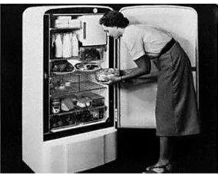
[image:14.612.221.435.275.446.2]The device found in more homes than any other appliance.
Figure 1: A 1950s fridge
The process to keep food cold by using an evaporative cooling system goes back a long time. The Romans used terracotta pots in water fanned by slaves to cool their food, but it was not until the 19th century that other liquids that would evaporate quicker if under compressions were discovered.
2
The natural ice industry was big business in the U.S. and Europe ice was cut from the lakes in winter and stored during the summer, by 1890 the U.S. was exporting 25 million tons of ice, but in Australia it was not cold enough to harvest ice in this way so it was very costly keep food cool.
In 1837 a journalist named James Harrison moved to Geelong Australia from Glasco and set about designing his own machine. His first machine did not work so he took it to England and with the help of a Doctor Seabe he got it working. Harrison returned to Australia in 1856 with the working machine, he was commissioned by a brewery to build a machine to cool beer and this was the first practical use of a refrigeration machine.
The first absorption machine was developed by Edmond Carre in 1850, using water and sulphuric acid. His brother, Ferdinand Carre developed the first
ammonia/water refrigeration machine in 1859. Many sources show that this machine of Ferdinand's was the first Refrigerator with no mention of Harrison, Perkins or his brother Edmond Carre.
Oven
An oven is an enclosed compartment for heating, baking or drying. It is most commonly used in cooking and pottery. Ovens used in pottery are also known as kilns. An oven used for heating or for industrial processes is called a furnace or industrial oven. Settlements across the Indus Valley Civilization were the first to have an oven within each mud-brick house by 3200 BC.
Many of the early brick ovens found throughout Europe are quite large in size. These oversized ovens likely belonged to wealthy land owners and were probably used at a price by the entire local community. The brick ovens in ancient Roman civilization, however, were used for both commercial and residential purposes. Many of these early brick ovens were smaller in size, as they may have only been used to feed one or two families at a time. Brick ovens were often used for business in eateries located throughout ancient Italy. These businesses have been unearthed to reveal a surprisingly more modern appearance than one might have expected. These ancient restaurants looked very much like contemporary pizzerias, and were often built with granite service counters. These eateries commonly sported a diverse menu that included rustic versions of modern-day pizza.
4
1.2 Background research
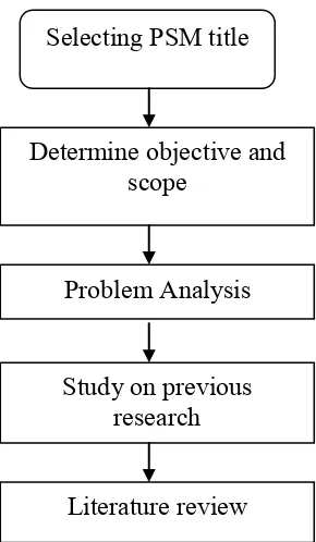
1.3 PSM flow chart
Figure 3: PSM flow chart Selecting PSM title
Determine objective and scope
Problem Analysis
Study on previous research
6
1.4 Problem Analysis
The heat dissipated by the condenser to the air is carried away by air that enters through the bottom and sides of the refrigerator and leaves through the top.
The heat can be used to develop warm oven at the top of the refrigerator. The oven is not required any external electrical source to generate the heat. Simulation of the heat dissipate from refrigerator can predict the possibility of using the heat from refrigerator compressor to warm the oven compartment.
1.5 Scope Objective
To simulate the oven compartment at the top of the refrigerator.
To investigate the temperature distribution from the condenser to oven compartment by experiment and simulation
Scopes
Study the refrigerator working principle Study the type of suitable oven to be used.
CHAPTER 2
LITERATURE REVIEW
2.1 Theoretical analysis and solution
Parts of a Refrigerator
Basic idea behind a refrigerator is to use the evaporation of a liquid to absorb heat. As the water evaporates, it absorbs heat, creating that cool feeling. Rubbing alcohol feels even cooler because it evaporates at a lower temperature. The liquid, or refrigerant, used in a refrigerator evaporates at an extremely low temperature, so it can create freezing temperatures inside the refrigerator.
There are five basic parts to any refrigerator:
Compressor
Heat-exchanging pipes - serpentine or coiled set of pipes outside the unit Expansion valve
Heat-exchanging pipes - serpentine or coiled set of pipes inside the unit
8
Figure 2.1: Basic parts of refrigerator
The Complete Refrigeration Cycle
Figure 2.6: Complete Refrigeration Cycle
The chosen oven
In the house appliance, there are a lot of type of oven has been sold. There is Dutch oven, microwave oven, reflector oven, solar oven, convection oven and a lot more. Each oven has its own system of work. For the project we choose the convection oven based on how its work and it efficiency.
10
By moving fast hot air past the food, convection ovens can operate at a lower temperature than a standard conventional oven and yet cook food more quickly. The air circulation, or convection, tends to eliminate "hot spots" and thus food may bake more evenly.
A convection oven will have about a 50 degree Fahrenheit (30 degree Celsius) reduction in cooking temperature, compared to a conventional oven. This comparison will vary, depending on factors including, for example, how much food is being cooked at once or if airflow is being restricted by using an over sized baking tray.
Many convection ovens also include a proofing capability using the same fan but at a much lower temperature. A residential double oven will often include the fan capability in only one of the two ovens. Convection ovens provide more uniform heat than regular ovens by moving the oven air away from both the heat source and the top of the oven cavity. Circulating hot air seals in natural juices from the start of cooking. With a convection oven, food cooks faster or at a lower temperature than it does in a regular oven.
Figure 4: Image of convection oven
The circulation of convection oven
In a regular oven, air is warmest close to the heat source. Placement of food is critical for best results since food cools the air immediately around it and the area near the elements may be too hot. When the air is still, heat rises from the source at the bottom and collects at the top of the oven. In the regular electric oven, food must be place in the centre of the oven for even baking and roasting results. The convection oven moves cool air away from the food. As hot air flows around the food, the cool air is recirculated past the source of heat. To use a convection oven most efficiently, the oven door must be kept closed as much as possible. Airflow must be maintained.
The air in the oven must circulate freely. Shape of food affects convection cooking. A long thin meat cooks faster than a bulky one of the same weight because more surface is exposed to moving hot air. Size of pan also must be considered. The same quantity of food cooks faster in two small pans than it does in one large pan since air can circulate more freely.