Performance Evaluation of Multiple Differential Detection for Third
Generation Mobile Communication System
1
M. S. Johal,
1M. K. Suaidi,
1A. R. Othman
1
Faculty of Electronics and Computer Engineering Universiti Teknikal Malaysia Melaka Locked Bag 1200, 75450 Ayer Keroh, Melaka.
Email: [email protected], [email protected], [email protected]
Abstract – Third generation mobile communication
system is widely used nowadays. One of its parameter standard, which is QPSK modulation has been adopted by International Telecommunication Union (ITU) to be used in IMT-2000. However, due to amplitude variations introduced in QPSK, a rather robust and reliable data modulation technique, namely the π /4-shift Differential QPSK is proposed. For detection purposes, two types of detectors are evaluated for their performance in AWGN and Rayleigh fading channels. A differential detection technique called multiple differential detection technique which uses maximum-likelihood sequence estimation (MLSE) of the transmitted phases is compared with conventional differential detection which uses symbol-by-symbol detection. By using some of the IMT-2000 standard parameters, the simulation results show that multiple differential detection scheme performs much better than conventional differential detection scheme.
Keywords: π/4-shift Differential QPSK, multiple differential detection, square root raised cosine Nyquist filter, multipath, intersymbol interference
1. Introduction
The current generation of mobile communication systems, which utilizes digital technology to provide voice and data services must provide high quality signal and data reproduction [1], [2]. International Mobile Telecommunication-2000 (IMT-2000), formerly known as Future Public Land Mobile Telecommunication System (FPLMTS), currently operating in the 2 GHz band on a worldwide basis for the satellite and terrestrial components is capable of offering a wider range of services including multimedia services, with the same quality obtained from the fixed telecommunication networks in many different radio environments [3]. However, these objectives are not easily met because it is well known to all mobile communication engineers and users that two of the major disturbances in the transmission of digital information over land-mobile link are the presence of fading and thermal-electric noise. In order
to reduce this problem, a more reliable data encoding method is necessary.
Several techniques have been proposed to reduce the effect of multipath fading channel. A differential detection technique for MPSK called multiple symbol differential detection has been proposed, which uses maximum-likelihood sequence estimation (MLSE) of the transmitted phases rather than symbol-by-symbol detection as in conventional differential detection [4]. It has been shown in [4] that for binary DPSK, extending the observation interval from N = 2 (for conventional differential detection) to N = 3 recovers more than half of the Eb / No loss of differential
detection versus coherent detection with differential encoding. Whereas for QPSK (M = 4), the improvement of Eb / No performance of observation
interval N = 3 relative to N = 2 is more than 1 dB. In [5], Abrardo et al. have presented the application of the differential detection algorithm proposed in [4] to the demodulation of a GMSK signal. This algorithm presents quite an attractive performance both in an AWGN and in a multipath channel as compared to coherent detection algorithm.
So far, no literature on performance evaluation on IMT-2000 or sometimes it is known as third generation mobile communication system employing multiple differential detection algorithm has been studied. Currently, the IMT-2000 has adopted QPSK modulation scheme to be used in time division duplex (TDD) mode. However, with QPSK, when the phase changes from 00 to 1800 , the signal amplitude must pass through zero, so there is an amplitude component in the transmitted signal [9]. The amplitude is constant at the sampling intervals but varies during the phase transitions. Therefore, in this paper, a more reliable QPSK modulation scheme with differential encoding (also known as π/4-DQPSK) is proposed. Furthermore, an effective way to recover the original information is of an even greater importance. A promising solution to reproducing the sent information is through the usage of a multiple differential decoder.
2. System Model
It is necessary to understand the details of the structure of an entire communication system in order to produce the algorithm for the differential detection scheme. Figure 1 shows the π/4-DQPSK transmitter model [6].
Figure 1: Block diagram of transmitter model
From the block diagram, the π/4-DQPSK baseband generator is represented in its equivalent form as the combination of a signal mapper, a differential encoder and a Nyquist filter. The input signal, bk , is an information word which consists a
sequence of bits, values of 0’s and 1’s. The signal mapper takes readings at every two bits and maps the value onto the QPSK signal space in a straightforward manner.
{00, 01, 10, 11} →{0, 1, 2, 3}
Now, the representation of the signal from the signal mapper is δk = γk ej
Ω
k , where γk and Ωk represent the
envelope and the phase, respectively. For all PSK signals, the envelope can be considered to be equal to 1 since it is constant. So the signal from the signal mapper is simply denoted as
δk = γk ejΩk , with Ωk = {±π/4, ±3π/4} (1)
Differential encoding of the sequence of δk ‘s yields
the sequence of differentially encoded symbols ck. For
example, PSK signals are differentially encoded as
(
)
]
exp[
11 1
k k k
k k
k
j
c
c
=
=
−⊕
Ω
−
−
φ
γ
δ
(2)with φk denoting the phase of ck and ⊕ modulo-2π
addition. The differential encoder simply converts the 2-bit symbols of the QPSK signal into 3-bit symbols of the π/4-shift DQPSK signal. The computation for this task is achieved by analyzing the transition of one QPSK point to the next. Hence, the signal leaving the differential encoder is denoted as
ck = ejθk , with θk = {0, ±π/4, ±2π/4, ±3π/4, π} (3)
After passing through the premodulation filter, the signal can then be represented as
( )
(
)
=
−
=
Lk T
k
h
t
kT
c
t
s
0
. (4)
In (4), T is the symbol duration, L is the number of symbols transmitted, and hT(t) is the impulse response
corresponding to HT (f) which is a well-known square
root α,
α
raised cosine filter [7]. The signal is now represented in two complex components. The values of the signal’s complex components are still in digital form at this stage but each complex component is now an 8-bit symbol.Before reaching the modulator, digital-to-analog (D/A) conversion must take place first. So, the 8-bit digital values become analog values. When the signal is modulated by the carrier frequency, it becomes
( )
t
=
{
s
( )
t
e
j( πfct+ρ)}
x
Re
2 (5)where fc is the carrier frequency and ρ is the initial
phase of the modulator.
In the propagation channel, x(t) is assumed to be corrupted by a mixture of multiplicative, non-selective fading, f(t) and AWGN, n(t) which introduces a one-sided power spectral density, No [7].
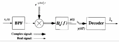
At the receiver, realization is achieved by the block diagram in Figure 2 below [7].
Figure 2: Block diagram of receiver model
The received signal is first passed through a wideband bandpass filter (BPF) to limit the Gaussian noise without distorting the information carrying signal. The signal is represented by
xr(t) = x(t)f(t) + n(t) (6)
It can be seen from the block diagram that the demodulator is composed of both a carrier down-converter and pre-detection filter. After undergoing the down-conversion process and filtering to remove the excess spectrum in the higher frequencies, the received signal is expressed as
( ) ( ) ( )
t
=
s
t
f
t
e
jρ+
n
( )
t
e
−j( πfct+ρ)
( )
(
)
( )
( )
=−
+
−
=
Lk
Q I
k j
t
jn
t
n
kT
t
h
c
e
t
f
0 ρ
(7)
where nI(t) and nQ(t) are the in-phase and quadrature
baseband components of the narrowband Gaussian noise, respectively. The new impulse response, h(t) , is corresponded to the product of HT(f)•HR(f). The
predetection filter, HR(f) is chosen to match the
Nyquist filter, HT(f) in the transmitter such that h(t)
satisfies Nyquist’s first criterion of preventing intersymbol interference (ISI). So, the criterion for the impulse response upon sampling would have to meet the following condition:
1 for k = 0
h(t) = (8)
0 elsewhere
Therefore, the sampling by the decoder of the signal y(t) at t = kT would yield yk = y(kT), which is denoted
by
( )
( )
(
f
kT
jf
kT
)
c
e
n
( )
kT
jn
( )
kT
y
j I Qk Q I
k
=
+
+
−
ρ
.
(9)
If we assume the decoder acts as a conventional differential decoder then it computes the phase change between symbols by operating on samples from the in-phase and quadrature components of the signal received from the demodulator. The signal, yk , from
the demodulator can be generalized into the following forms for the in-phase and the quadrature of its complex components as shown below:
(
θ
+
ϕ
)
=
kk
I
cos
(10)and
(
θ
+
ϕ
)
=
kk
Q
sin
. (11)The element θk represents the points on the π/4-shift
DQPSK signal space and the ϕ represents the distortion caused by the fading, noise and the carrier’s phase lag. Now, the phase change between two symbols can be calculated by the following two formulae:
d
k[ ]
I
=
I
kI
k−1+
Q
kQ
k−1(
θ
+
ϕ
) (
θ
+
ϕ
)
+
(
θ
+
ϕ
) (
θ
+
ϕ
)
=
cos
kcos
k−1sin
ksin
k−1(
θ
−
θ
)
+
(
θ
+
θ
+
ϕ
)
=
0
.
5
cos
k k−10
.
5
cos
k k−1
(
θ
−
θ
)
−
(
θ
+
θ
+
ϕ
)
+
0
.
5
cos
k k−10
.
5
cos
k k−1(
1)
cos
−
−=
θ
kθ
k (12)[ ]
=
k k−1+
k k−1k
Q
Q
I
I
Q
d
(
θ
+
ϕ
) (
θ
+
ϕ
)
−
(
θ
+
ϕ
) (
θ
+
ϕ
)
=
sin
kcos
k−1cos
ksin
k−1(
θ
−
θ
)
+
(
θ
+
θ
+
ϕ
)
=
0
.
5
sin
k k−10
.
5
sin
k k−1(
θ
−
θ
)
−
(
θ
+
θ
+
ϕ
)
−
0
.
5
sin
k k−10
.
5
sin
k k−1(
1)
sin
−
−=
θ
kθ
k (13)where dk[I] and dk[Q] are the changes in magnitude of
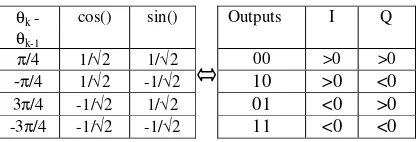
the in-phase and the quadrature components. Notice that each component changes with respect to the phase difference between the two symbols. Using this knowledge, a decision on the output of the 2-bit symbols can be made based on the technique demonstrated by Table 1.
The multiple differential decoder is an elaboration on the conventional differential decoder. Generally, as in [8], the term “multiple differential detectors” refers to differential detectors which decode the receiver signal over a multi-symbol interval. The multiple order of the detector corresponds to the prediction order of the detector [6]. If the prediction order of the multiple differential detector is set to 1, then the current multiple differential detector is just a normal conventional differential detector. Then, torealize a multiple differential detection scheme, a predetermined number of memory latches is chosen to store the phase change values. Then, a decision-maker would process the output 2-bit signal based on the pattern of the phase changes. The block diagram in Figure 3 illustrates the general format of the multiple differential detection scheme.
Table 1: Output references of the conventional differential decoder
θk -
θk-1
cos() sin() Outputs I Q
π/4 1/√2 1/√2 00 >0 >0
-π/4 1/√2 -1/√2 10 >0 <0
3π/4 -1/√2 1/√2 01 <0 >0
Figure 3: Block diagram of multiple differential detection scheme
Prior to generating the 2-bit output, the decision-maker computes the pattern of one phase change value to the next. Such phase changing patterns would correspond to the values of the points on the π/4-shift DQPSK signal space. This recognition of phase changing pattern can be achieved by referring to a look-up table and the signal space maps of both QPSK and π/4-shift DQPSK which are stored in permanent memory areas. Table 2 shows how the processor computes the pattern of phase changes.
Table 2: Mapping for pattern in phase changes
Points on ππππ/4-shift DQPSK Signal Space
0 1 2 3 4 5 6 7
000 001 010 011 100 101 110 111 Additive Constants
Outputs
001 010 011 100 101 110 111 000 001 00
011 100 101 110 111 000 001 010 011 01
101 110 111 000 001 010 011 100 101 11
Next Signals
111 000 001 010 011 100 101 110 111 10
From the mapping table, the processor initially maps the first few signals onto the points of π/4-shift DQPSK signal space. Then, as subsequent signals arrive, each one would be mapped according to what point the previous signal is located. For example, the previous signal is mapped at point 3 in column 4, then the next incoming signal can only be mapped with values which fall in column 4. Each incoming signal is also converted to its equivalent value as a constant. This is accomplished simply by subtracting, circular shifting method, the value of the current signal by that of the previous signal. A 2-bit decoded output symbol is then produced by logical derivation from the constant.
3. Simulation Results and Discussion
Simulation results are presented for the proposed scheme whereby the simulation methodology for the bit error rate uses the well-known Monte Carlo simulation techniques. The simulation begins with
system with conventional differential detection scheme in two different environments. Since the overall transceiver system under investigation is meant for IMT-2000, then some standard parameter specifications for third generation mobile communication system will be used in the simulation. For simplicity, a maximum data rate of 2 Mbps, root raised cosine Nyquist filter, α = 0.22 and operating frequency of 2 GHz are chosen as common parameter for comparison purposes.
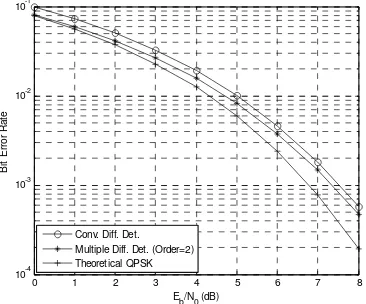
Case 1: Performance comparison of conventional differential detection scheme and multiple differential detection scheme in AWGN channel
Figure 4 shows that the performance of π /4-DQPSK system with multiple differential detection is slightly better than conventional differential detection scheme. For example, at a bit error rate, BER = 10-3 , multiple differential detector performs slightly better by 0.2 dB than its conventional differential detector. This simulation is used as a reference for the second investigation.
0 1 2 3 4 5 6 7 8
10-4 10-3 10-2 10-1
E
b/N0 (dB)
B
it
E
rr
o
r
R
a
te
Conv. Diff. Det. Multiple Diff. Det. (Order=2) Theoretical QPSK
Figure 4: Performance comparison of conventional and multiple differential detection schemes in AWGN
channel
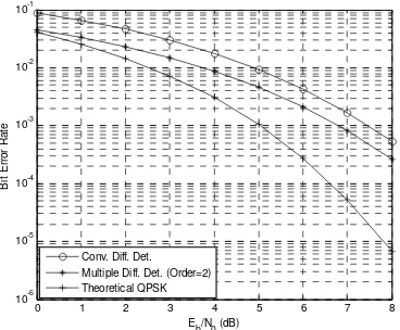
Case 2: Performance comparison of conventional differential detection scheme and multiple differential detection scheme in AWGN and Rayleigh fading channel
In this simulation, the fading factor of the overall communication system needs to be determined. The fading factor refers to how much of the original signal is affected by fading. This value is calculated by dividing the bandwidth value of the channel by the data rate of the signal. Knowing that the operating frequency is at 2 GHz and the symbol rate is set at 1 Mbps, then the fading factor, BFT is calculated to be
0.000185. Normalizing B to the symbol rate 1/T, the
Phase-Change Detector
dk-1 dk-2 dk-l
I
Q
Prediction/Cancellation Processing Unit
dk[I]
dk[Q]
interference changes with respect to the symbol duration. As well known, the BFT product is an
important parameter when evaluating the performance of digital modulation schemes transmitted over a fading channel. It should be noted that from the open technical literature there exists no clear definition as to which BFT product results in fast fading. For the
purpose of this project, however, it will be assumed that for BFT > 0.1 we have fading.
As expected, the bit error rate for both schemes will deteriorate in the Rayleigh fading channel from Figure 5. However, the performance of multiple differential detection scheme improves by gaining about 1 dB at BER = 10-2. This clearly shows that the proposed multiple differential scheme performs better than conventional differential detection scheme for
π/4-DQPSK signaling in IMT-2000.
0 1 2 3 4 5 6 7 8
10-6 10-5 10-4 10-3 10-2 10-1
Eb/N0 (dB)
B
it
E
rr
o
r
R
a
te
Conv. Diff. Det. Multiple Diff. Det. (Order=2) Theoretical QPSK
Figure 5: Performance comparison of conventional and multiple differential detection schemes in AWGN
and Rayleigh fading channel
4. Conclusion
This paper studies the performance of π/4-DQPSK signaling employing either multiple differential detection scheme or conventional differential detection scheme in AWGN and Rayleigh fading channels. The differential encoding of QPSK modulation was intended to provide a more reliable data encoding technique by reducing the amplitude variation problem in conventional QPSK. Furthermore, by implementing the multiple differential detection scheme the performance of overall transceiver is much better than conventional differential detection scheme in both channels. As a conclusion, the proposed detection system is feasible and can be applied in current third generation mobile communication system.
References
[1] W.C.Y. Lee, Mobile Cellular Telecommunication
Systems, McGraw Hill, New York, 1989.
[2] D.J. Goodman, “Cellular packet communications”, IEEE Trans. Commun., vol. 38, pp. 1272-1280, Aug. 1990.
[3] IEEE Personal Communications Magazine, vol. 4 no. 4, August 1997.
[4] D. Divsalar and M.K. Simon, “Multiple-Symbol Differential Detection of MPSK”, IEEE Trans. on
Communications, vol. 38, no. 3, March 1990.
[5] A. Abrardo, G. Benelli and G.R. Cau, “Multiple-Symbol Differential Detection of GMSK for Mobile Communications”, IEEE Trans. on
Vehicular Technology, vol. 44, no. 3, August
1995.
[6] D.P. Bouras, P.T Mathiopoulus and D. Makrakis, “Optimal Detection of Coded Differentially Encoded QAM and PSK Signals with Diversity Reception in Correlated Fast Rician Fading Channels”, IEEE Trans. on Vehicular Technology, vol. 42, no. 3, August 1993.
[7] J.G. Proakis, Digital Communications, McGraw- Hill, New York, 2001.
[8] D. Makrakis and P.T Mathiopoulos, “Optimal Decoding in Fading Channels: A Combined Envelope, Multiple Differential and Coherent Detection Approach”, in Proc. GLOBECOM’89, Dallas, TX, pp. 1551-1557, Nov. 1989.
[9] J. A. Phillips and G. Mac Namee, Personal Wireless Communication with DECT and PWT,