SUPERVISOR DECLARATION
“I hereby declare that I have read this report and in my opinion this report is sufficient in terms of scope and quality for the award of the degree of
Bachelor of Mechanical Engineering (Design & Innovation)”
Signature : ...
Supervisor’s Name : Shafizal Bin Mat
ii
DESIGN AND ANALYSIS OF DUMBWAITER LIFT FOR PUBLIC BUILDING USE
WAN AZRIANA BINTI WAN AZAHAR
This report is submitted to the Faculty of Mechanical Engineering In partial fullfillment of requirement for the award of Bachelor of Mechanical Engineering (Design & Innovation)
Faculty of Mechanical Engineering Universiti Teknikal Malaysia Melaka
iii
DECLARATION
“I hereby declare that the work in this report is my own except for summaries and quotations which have been cited”.
Signature : ...
Author’s Name : Wan Azriana Binti Wan Azahar
iv
DEDICATION
Highest special thankful wishes to both my lovely parents
Wan Azahar Bin Yacob &
Suhana Binti Hashim
Also
Fellow classmates
v
ACKNOWLEDGEMENT
Firstly, I would like to express my gratefulness for ALLAH S.W.T for His blessings and divine grace; I am able to complete my Final Year Project (BMCU 4984) without many problems and difficulties.
Next, I would like to thank my supervisor, Mr Shafizal bin Mat, who had willing to offer his support throughout my final year project and until this report is completed. He has never stop to support me in the best way through finding the information about my project and also on the problem solving methods. His experience in this related topic is so valuable in my case study.
Apart from that, I would like to extend my thankful wishes also to all lecturers, classmates, all my friends no matter in UTeM or other places, and also them who have contributed in helping me to finish my project and report. A lot of thanks also to UTeM librarian staffs for their guidance and advices when I went to library to complete my research.
Not to forget, I would like to extend my appreciation to my family who keep supporting me in giving advices and moral support so I became stronger and more determined to finish this project. All the useful experiences that I had gained and learned really give me many experiences which will be useful when I am in working fields in future.
vi
ABSTRACT
vii
ABSTRAK
viii
TABLE OF CONTENTS
CHAPTER TITLE PAGE
SUPERVISOR DECLARATION i
DECLARATION iii
DEDICATION iv
ACKNOWLEDGEMENT v
ABSTRACT vi
ABSTRAK vii
TABLE OF CONTENTS viii
LIST OF TABLES xi
LIST OF FIGURES xiii
CHAPTER 1 INTRODUCTION
1.1 Background of Study 1
1.2 Problem Statement 2
1.3 Objectives 3
1.4 Scope 4
1.5 Methodology 5
CHAPTER 2 LITERATURE REVIEW
2.1 Introduction 6
2.2 Dumbwaiter Lift Components 7
2.2.1 Cart 9
2.2.2 Guide Rail 10
2.2.3 Motor 11
2.2.4 Controller 12
2.2.5 Stations 13
2.2.6 Interlock 14
2.2.7 Frame or Enclosure 15
2.3 Product Development Process 16
ix
2.5 3D CATIA CAD Software 21
2.6 FEA Analysis 23
CHAPTER 3 METHODOLOGY
3.1 Introduction 25
3.2 Flowchart of Case Study 27
3.2.1 Literature Review 28
3.2.2 Problem Statement 29
3.2.3 Synthesis 29
3.2.4 Conceptual Design 30
3.2.5 Selection Design 31
3.2.6 Detail Design 32
3.2.7 Analysis 33
3.2.8 Results and Discussion 33
3.2.9 Presentation 34
3.3 Method of Information Gathering 35
CHAPTER 4 CONCEPTUAL DESIGN
4.1 Introduction 36
4.2 Engineering Design Specifications 36
4.2.1 Product Decomposition 37
4.2.2 Morphological Chart 38
4.3 Conceptual Design 38
4.3.1 Conceptual design development 39
4.3.2 Concept generation 39
4.4 Existing Product 40
4.5 Concept Design Generation 41
4.5.1 Concept 1 41
4.5.2 Concept 2 43
4.5.3 Concept 3 45
4.6 Summary 47
CHAPTER 5 CONCEPTUAL SELECTION
5.1 Introduction 48
x
CHAPTER 6 DETAIL DESIGN
6.1 Introduction 50
6.2 Part Drawings 50
6.3 Assembly Drawing 55
6.4 Exploded Drawing 56
6.5 Summary 57
CHAPTER 7 DATA ACQUISITION
7.1 Introduction 58
7.2 Operational framework 59
7.3 Critical part selection 60
7.4 Analysis preparation 60
7.4.1 RULA Analysis 61
7.4.2 Stress Analysis 62
7.5 Data Collection 63
7.6 Summary of Chapter 63
CHAPTER 8 RESULTS AND DISCUSSION
8.1 Introduction 64
8.2 Analysis 65
8.2.1 Stress Analysis 65
8.2.2 RULA Analysis 68
8.3 Factor of Safety 71
8.4 Comparison of Result 72
8.5 Summary 73
CHAPTER 9 CONCLUSION AND RECOMMENDATION
9.1 Conclusion 74
9.2 Recommendation 75
REFERENCES 76
BIBLIOGRAPHY 79
xi
LIST OF FIGURES
NO TITLE PAGE
2.1 Full Assembly Of Dumbwaiter Lift 8
2.2 Dumbwaiter Cart 9
2.3 Guide Rail 10
2.4 Motor 11
2.5 Controller 12
2.6 Stations 13
2.7 Interlocks 14
2.8 Frame of Dumbwaiter Lift 15
2.9 Product Development Process 16
2.10 Area Of Injury 19
2.11 Example of CAD Drawing Of Dumbwaiter Lift 21
2.12 Example of FEA Analysis 23
3.1 Flow of Project 27
4.1 Methodology Integration 37
4.2 Dumbwaiter Lift Decomposition 37
4.3 Existing Model Of Dumbwaiter Lift 40
4.4 Concept 1 Sketch 41
4.5 CAD Drawing of Concept 1 42
4.6 Concept 2 Sketch 43
4.7 CAD Drawing of Concept 2 44
4.8 Concept 3 Sketch 45
xii
6.2 Exploded Drawing 56
7.1 Operational Framework 59
7.2 RULA Analysis Flowchart 61
7.3 Stress Analysis Flowchart 62
8.1 RULA Analysis Using CATIA V5R20 68
8.2 RULA Result For Existing Design (Right Side) 69
8.3 RULA Result For Concept Design (Right Side) 69
8.4 RULA Result For Existing Design (Left Side) 70
xiii
LIST OF TABLES
NO TITLE PAGE
2.1 RULA Analysis Score Table 19
4.1 Morphological Chart 38
4.2 Concept 1 Summary 42
4.3 Concept 2 Summary 44
4.4 Concept 3 Summary 46
5.1 Pugh’s Concept Selection Method 49
6.1 Part Drawing Details 51
7.1 Critical Part Description 60
8.1 Existing Material Results 65
8.2 Existing Analysis Results 66
8.3 Conceptual Analysis Results 67
8.4 Result Comparison Summary 72
8.5 Comparison of RULA Analysis (Right Side) 73
xiv
LIST OF APPENDICES
NO TITLE PAGE
1 Gantt Chart PSM 1 80
2 Gantt Chart PSM 2 81
3 RULA Assessment Worksheet 82
4 Existing Design Specification 83
CHAPTER 1
INTRODUCTION
1.1 BACKGROUND OF STUDY
In these modern times, people are constructing items to help simplify daily routines or chores. For example, escalators and elevators have been used widely in buildings instead of stairs for mare comfort and speed of getting people from one floor to another. A dumbwaiter is a smaller form of an elevator; however, it is not used for transporting people, but is usually to carry goods such as laundry, groceries or meals to and from different floors.
Dumbwaiters can be operated by manually pulling ropes to elevate the carts and also operated by using electricity, which the user only needs to push a button to operate the dumbwaiter. A simple dumbwaiter usually includes a cart to put items, a guide rail for ease of cart movement, motor for electric operated dumbwaiter, a controller, stations to where the goods are sent, interlocks for safety purposes, and limit switches as sensors (Pinciotti, 2011).
2
Decorative materials can be used for the outer part, such as doors and buttons for the dumbwaiter.
1.2 PROBLEM STATEMENT
It is very important to know the problem statement before conducting a study. The first problem with the existing dumbwaiter is the ergonomics factor. Due to its smaller size compared a normal people elevator, the size, loading and unloading item process needs to meet the ergonomics of the people because the dumbwaiter lift will be used by members of the public.
The second problem is that the dumbwaiter needs to be able to carry goods that weigh at least 100kg. Strength of the pulling mechanism and the cart itself needs to be sturdy to withstand the load.
3
1.3 OBJECTIVES
Objectives can be defined as the goals or target that needs to be achieved at the end of the project. The objectives need to be fulfilled in order to complete the project at hand. The objectives of this project are:
To design and propose a few conceptual designs of a dumbwaiter lift for public building usage
To analyze the conceptual designs and obtain the Factor of Safety
For the first objective, the goal is to produce a few conceptual designs of the dumbwaiter in order to find practical models that can be installed in a public building. The concept will be based on existing dumbwaiters in the market in order to find rooms of improvements.
4
1.4 SCOPE
This study will be based on the existing dumbwaiters available in the market and new concept development of the dumbwaiter. The scope of this project is to cover case study through literature reviews and journals on dumbwaiters, elevators or lifts and also the analysis involved.
The scope of this study includes using the CATIA software to develop conceptual designs to be presented. Furthermore, the CATIA software will also be used to analyze the ergonomics, as well as stress and strain on the proposed design. Both analyses are carried out in order to get the factor of safety and to introduce a design that is comfortable to use by the people who are using the dumbwaiter lift.
5
1.5 METHODOLOGY
The research of this project will be conducted through literature reviews, journals and also web searches. Furthermore, information will be produced from suppliers, contractors and also maintenance crew through interviews, so that hands on problems can be detected and improved further.
In order to achieve the optimum design, the phases and interactions of the design process will be followed accordingly. This includes identification of need, definition of problem, synthesis, analysis and optimization, evaluation and presentation. In order to determine the needs of customers and engineering, a House of Quality or Product Decomposition will be constructed to evaluate the important needs of the new dumbwaiter concept.
6
CHAPTER 2
LITERATURE REVIEW
2.1 INTRODUCTION
A dumbwaiter lift can be defined as a mechanism that uses a pulley system as a transportation device for carrying goods between floors of a building. The modern version of the device is usually driven by a motor, while early designs use manual labor to drive the cart with the help of a pulley system. A dumbwaiter lift is usually installed where goods need to be moved constantly to different floors or to a private room without using humans to transport them. This is due to privacy concerns, delivery time constraint, labor reduction and ease of delivery.
It is estimated that the dumbwaiter lift usage started at the beginning of the 19th century or earlier. The “Encyclopedia of College, Farm and Villa Architecture and Furniture” in 1834 called the dumbwaiter lift in London as “Rising Cupboards”. The said published article also contains sketches of the contraption that operated on the same principle of the dumbwaiter lift.
7
Now, the dumbwaiter lift is used in households with a basement to transport groceries, general buildings such as hospitals and libraries and also in some hotels, applied to their grand suites to better serve patrons. With the help of modern electronics, users only need to load the dumbwaiter cart with the items that need to be transported, and push the control button to determine the floor destination of the goods.
2.2 DUMBWAITER LIFT COMPONENTS
According to Jill Pinciotti (2011), electric dumbwaiter lifts have a track system to assist the cart’s movement and are powered by an electric motor to raise or lower the dumbwaiter cart. Also, a dumbwaiter lift is designed almost like a normal elevator lift, with safety brakes and interlocks to prevent the cart from moving when the door is open.
George W. Gibson (2009) states in his article that the structure of load bearing structures, such as suspension ropes, cart frames, bracings, platforms, cart, guide shoes and miscellaneous supports, including a counterweight.
Referring to planning guides and installation instructions from various sources and the Department of Safety and Health (DOSH) Melaka, it can be deduced that the main components of a dumbwaiter lift are:
1. Cart 2. Guide rail 3. Motor 4. Controller 5. Stations 6. Interlock
8
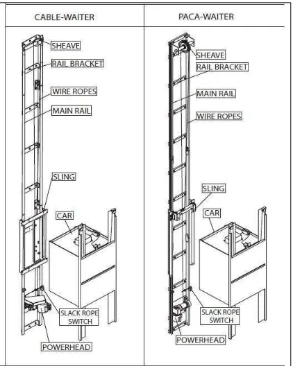
Figure 2.1 Full Assembly of Dumbwaiter Lift (Source: Waupaca Elevator Company Inc. , 2011)
9
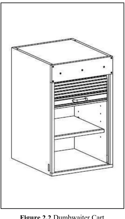
2.2.1 Cart
The cart is one of the key components of a dumbwaiter lift. It is shaped like a box, with one or more doorway depending on the design and customer requirement. It functions as the carrier of the goods between floors.
[image:23.595.217.422.274.633.2]The cart will be attached to the sling and rail bracket with a wire rope. The figure below shows a dumbwaiter cart when it is dismantled from the whole contraption.
Figure 2.2 Dumbwaiter Cart
10
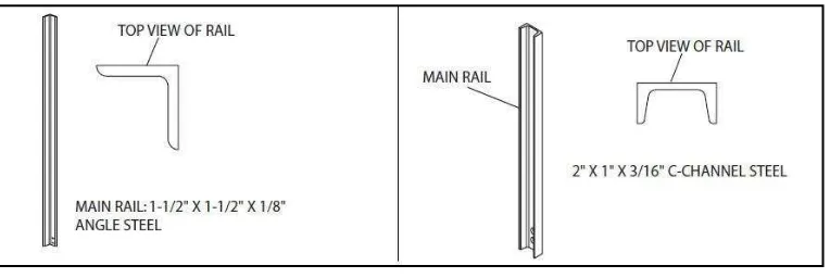
2.2.2 Guide Rail
The guide rail is used to provide a convenient movement of the cart when it goes up and down between floors, without it banging on the side of the enclosure or frame.
[image:24.595.151.533.276.404.2]The guide rail will be installed along with the frame a form of truss to further enhance the structure of the complete dumbwaiter lift. There are a few types of guide rails available, as shown in the figure below.