UNIVERSITI TEKNIKAL MALAYSIA MELAKA
DESIGN OF DEFECTED REFLECTOR ANTENNA
This report submitted in accordance with requirement of the Universiti Teknikal Malaysia Melaka (UTeM) for the Bachelor’s Degree in Electronic Engineering
Technology (Telecommunications) with Honours
by
NUR AINNA BINTI ABDUL RAHIM
B071110035
900508-04-5458
UNIVERSITI TEKNIKAL MALAYSIA MELAKA
BORANG PENGESAHAN STATUS LAPORAN PROJEK SARJANA MUDA
TAJUK: Design of Defected Reflector Antenna
SESI PENGAJIAN: 2014/15 Semester 2
Saya NUR AINNA BINTI ABDUL RAHIM
mengaku membenarkan Laporan PSM ini disimpan di Perpustakaan Universiti Teknikal Malaysia Melaka (UTeM) dengan syarat-syarat kegunaan seperti berikut:
1. Laporan PSM adalah hak milik Universiti Teknikal Malaysia Melaka dan penulis. 2. Perpustakaan Universiti Teknikal Malaysia Melaka dibenarkan membuat salinan
untuk tujuan pengajian sahaja dengan izin penulis.
3. Perpustakaan dibenarkan membuat salinan laporan PSM ini sebagai bahan pertukaran antara institusi pengajian tinggi.
4. **Sila tandakan ( )
SULIT
TERHAD
TIDAK TERHAD
(Mengandungi maklumat yang berdarjah keselamatan atau kepentingan Malaysia sebagaimana yang termaktub dalam AKTA RAHSIA RASMI 1972)
(Mengandungi maklumat TERHAD yang telah ditentukan oleh organisasi/badan di mana penyelidikan dijalankan)
Alamat Tetap:
NO. 123 Taman Bukit Puteri
Bukit Beruang, 75450
i
DECLARATION
I hereby, declared this report entitled “Design of Defected Reflector Antenna” is the results of my own research except as cited in references.
Signature : ……….
Author’s Name : ………
ii
APPROVAL
This report is submitted to the Faculty of Engineering Technology of UTeM as a partial fulfillment of the requirements for the degree of Bachelor’s Degree in Electronic Engineering Technology (Telecommunications) with Honours. The member of the supervisory is as follow:
iii
ABSTRAK
iv
ABSTRACT
v
DEDICATION
To my beloved parents, Mr. Abdul Rahim bin Mat Dom and Madam Zahara binti Mohamed that have sacrificed so much and was always encouraging and support for the sake of your daughter to be good in future and a beneficial person to the family, religion,
vi
ACKNOWLEDGEMENT
Syukur Alhamdulillah to Allah almighty for His grace in providing me the power and capability in bringing this research to the time being.
vii
2.3.3 Advantage and Disadvantage of Microstrip Patch Antenna 12
2.3.4 Comparison Between Circular and Rectangular Microstrip Patch 13 Antenna
2.4 Defected Ground Structure 14
viii
CHAPTER 3 : METHODOLOGY 18
3.1 Project Planning 18
3.2 Purpose Design Layout for Microstrip Patch Antenna 22 3.3 Design Circular Patch Antenna using Computer Simulation Technology 23 (CST) software.
3.4 Hardware ( fabrication ) Circular Patch Antenna. 25
3.4.1 The Process of UV Curing 25
3.4.2 UV PCB developer 26
3.4.3 Etching and Board Cutting 27
3.4.4 Installation Port and Measurement 28
CHAPTER 4 : RESULT AND DISCUSSION 29
4.1 Result and Discussion 29
4.2 Project Analysis 35
CHAPTER 5 : CONCLUSION AND FUTURE WORK 37
5.1 Project Conclusion 37
5.2 Suggestion and Enhancement 38
REFERENCES 40
APPENDICES
ix
LIST OF TABLES
2.3.3 2.3.4
Characteristics of three type microstrip antenna
The advantage and disadvantages of microstrip antenna.
10 12
x
LIST OF FIGURES
2.3.1 2.3.2
Microstrip antennas configuration
Four basic categories microstrip antennas
8 8 2.4.1.1
2.4.1.2
Some common configurations for DGS resonant structures.
Equivalent circuit of a DGS element.
15
Proposed design layout for circular patch antenna (a) top view,
patch antenna (b) bottom view, ground CST software used to design antenna.
Design circular patch antenna using Computer Simulation Technology (CST) software.
Photocopy design onto transparent paper Ultraviolent Machine
Doing the PCD developer The circular patch antenna
Simulation result circular patch antenna without defected ground structure (DGS)
Front view circular antenna Back view circular antenna Bottom view the port antenna
Return loss of the basic circular patch antenna with DGS Hardware of circular patch antenna
xi
LIST OF ABBREVIATIONS, SYMBOLS AND
NOMENCLATURE
AIA - Active Integrated Antenna
CST - Computer Simulation Technology DGS - Defected Ground Structure
1 .
1.1 Background
Nowadays, Malaysia's communications systems has grown and developed into the most important tool for communication between the faster and easier to use. In communication systems, antenna has become one among the main medium for transmitting and receiving information. Generally its antenna ( or aerial ) is an electrical device that converts electrical energy into radio waves, and vice versa, and it is usually used with a radio transmitter or receiver.
For the reflector antenna systems for ground based and line of site communication systems play a vital role in the transfer of information for both military and civilian communication purposes. Previously, these reflector antenna systems have been designed predominantly on the antenna’s transmitting and receiving the characteristics.
For the Defected ground structure (DGS) is an etched periodic or non-periodic cascaded configuration defect in ground of a planar transmission line (e.g., microstrip, coplanar and conductor backed coplanar wave guide) which disturbs the shield current distribution in the ground plane cause of the defect in the ground.
2 In this project is to design of defected reflector antenna by using the compact size microstrip antenna with defected ground structure (DGS) method for communication system. The microstrip antenna is known as printed antenna and it is commonly square in shape rectangular and it have better prospects and more advantages for design antenna in the order to design the compact size antenna. The ground element of the proposed antenna is taken the form of defected ground structure (DGS) where that method is a unique techniques to reduce the antenna size.
The antenna will design and simulate by using the software Computer Simulation Technology (CST) follow by fabricate (hardware). So design the antenna with the defected ground structure, the antenna size is reduced for a particular frequency as compared to the antenna size without the defect in the ground. In case study, research will be focus on how the defected ground structure (DGS) will affect the reflector antenna and change the antenna properties. The parameter and performance of antenna design will be investigated through a number of design simulations. Last but not least, microstrip antenna with defected ground structure method for communication system application will be design to see how far the DGS method can give an advantages in the development of antenna for communication system.
1.2 Problem Statement
3
1.3 Project Objective
The objective of this project is to propose design, simulate, and fabricated the defected reflector antenna by using the Microstrip antenna and with a consider structure of defected ground structure (DGS). This is because the Microstrip antenna with defected ground structure (DGS) is a best choice to meet the requirements in order to create the antenna with size reduction for communication system or mobile communication.
1.4 Project Scope
In the scope of this project are limitation to the design of the microstrip antenna with Defected Ground Structure (DGS) and the applications are for the communication system or mobile communication. In this part it will design by using Computer Simulation Technology (CST) software which is this software offers the accurate, efficient computational solutions and follow by hardware components. The design of this antenna involves the antennas available and consider the defected ground structure (DGS) and the rate of antenna reflections occur.
1.5 Project Significant
4
1.6 Conclusion
5 Literature review is a evaluation of previous research. It is actually the summary and synopsis the same topic or at least the related article belongs to the research to be done. All the important topic that related with project will be in summarized together and show the reasons why me is pursuing this particular research program.
2.1 Introduction
In order to design of defected reflector antenna, research had been made in scope of this project to studying the concept use, their method, do the comparison and select the best one, to be design in this project. Research is done by comparing the suitable antenna to be design with defected ground structure. All the aspect will be compared to determine the advantages and disadvantages for each aspect to be design.
This chapter is discussing briefly about the suitable methods used in order to complete this project. Research about the antenna use, selection of microstrip antenna, and method use for defected ground structure (DGS) had been done before start doing this project. Meanwhile, the choice to meet the requirements in order to create the antenna for communication system or mobile communication also had been studies. In the research of microstrip antenna, the specification and feature of microstrip antenna with defected ground structure (DGS) is study to fulfill the requirement of this project.
6
2.2 Antenna
The IEEE Standard Definitions of Terms for Antenna defines the antenna or aerial as "a means for radiating and receiving radio waves". In other words, the antenna is a transitional structure between free space and guiding device. For wireless communication systems, the antenna is one of the most critical components[1]. Antennas, by definition are devices that convert time-varying voltages into a radiated electromagnetic field (transmitting) and vice-versa (receiving)[6].
In that journal, the authors state that antenna is one of the devices that radiate and receiving radio waves to make a communication or to sending information. Antenna a design of transducer for transmission or receiving electromagnetic waves. In the other words, the antenna is a transitional structure between free space and guiding devices. The antenna become the most critical components because nowadays in Malaysia we are using the wireless communication systems as a primary communication to connect with others in the distance. For the antenna the guiding device or transmission line may take the form of a coaxial line or a hollow pipe (waveguide), and it is used to transport electromagnetic energy from the transmitting source to the antenna, or from the antenna to the receiver.
7
2.3 The Microstrip Antenna
The antenna is device or transducer, it is used to transport electromagnetic energy from the transmitting source to the antenna, or from the antenna to the receiver. Microstrip antennas have several advantages over conventional microwave antenna and therefore are widely used in many practical applications.
Micro strip antenna also known as printed antenna, it is commonly square in shape, rectangular, circular and elliptical. This antenna is narrow band, wide-beam fabricated by etching the antenna element pattern in metal race; some patch antennas do not use electric dielectric spacers and are usually cheap to manufacture. This Micro strip antenna is possibly used as a sensory device alternatively it can be used for keeping balance in air craft’s, missiles, satellite and also used in Musical Instrument Museums Online ( MIMO). [13]
A microstrip antenna is a kind of antenna used to process ultra-high frequency signals. It is often used as a satellite radio or cell phone receiver or is mounted on an aircraft or spacecraft. This type of antenna has the advantage that it costs little to make but the disadvantage that it has limited bandwidth.
An antenna is a device designed to transmit or receive electromagnetic waves. It is used in radio equipment to convert radio waves into electrical currents or electrical currents into radio waves. The only difference between a transmitting antenna and a receiving antenna is the direction the signal is travelling. A microstrip antenna is used to transmit or receive signals in the ultra-high frequency spectrum. These are waves with frequencies between 300 MHz and 3000 MHz (3GHz).
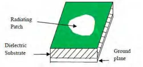
8 Figure 2.3.1: Microstrip antennas configuration
2.3.1 Characteristics of Microstrip antennas
Microstrip antennas are characterized by a larger number of physical parameters than are conventional microwave antennas. They can be designed to have many geometrical shapes and dimensions [2]. The microstrip antennas can be divided into the four basic categories as show in Figure 2.3.2
Figure 2.3.2: Four basic categories microstrip antennas
Microstrip antenna
Microstrip patch
antenna Microstrip dipoles Printed slot antennas
Microstrip travelling-wave
9
2.3.2 Comparison the microstrip antenna
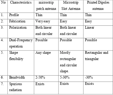
In my design of antenna the microstrip patch antenna have been selected because the microstrip patch antenna have more advantages and better prospects. They are lighter in weight, low volume, low cost, low profile, smaller in dimension and ease of fabrication and conformity[2]. Microstrip antenna design for different applications such as cross polarization reduction and mutual coupling reduction etc., it can also be used for the antenna size reduction[4]. In the part to choose the type of antenna to be design the characteristics of three type microstrip antenna are compared in table 2.3.3.
10 Table 2.3.3: Characteristics of three type microstrip antenna
No Characteristics microstrip patch antenna
Exists Exists Exists
The most common type of microstrip antenna is the microstrip patch antenna. It is made by etching the antenna pattern into metal trace. This etching is bonded to a layer of insulating material, such as plastic, certain ceramics, glass, or certain types of crystal, then the insulating layer, known as the dielectric substrate, is bonded to a layer of metal. It is possible to create a microstrip antenna without a dielectric substrate. The resulting antenna is not as strong but gets better bandwidth, meaning it can process more information at once.
11 The size of the microstrip antenna is inversely proportional to its frequency. That means the larger the antenna, the lower the frequency it is able to detect. For this reason, microstrip antennas are generally used for ultra-high frequency signals. A microstrip antenna capable of sensing frequencies lower than microwave would be too large to use.