DOI: 10.12928/TELKOMNIKA.v14i3A.4430 194
Dynamic Simulation Analysis of Working Device for
Hydraulic Excavator Based on ADAMS
Caiyuan Xiao1, Guiju Zhang*2 1,2
Department of Mechanical and Energy Engineering, Shaoyang University, Shaoyang, 422004, P. R. China
2
College of Mechanical and Electrical Engineering, Central South University, Changsha, 410083, P. R. China
*Corresponding author, e-mail: [email protected]
Abstract
Taking a certain type of excavator as the research object, the 3D models of its working device were established and assembled by 3D design software Pro/E. And then the 3D models were imported into dynamics simulation software ADAMS to build the virtual prototype system after adding constraints and load. Through simulation analyzing on working device during one work cycle time, the mainly articulated point’s load stress curves were obtained for working device. Thus proved that its movement characteristics is in line with the actual working condition, which provides the theory reference of design and analysis and uses as a design basis for hydraulic excavator working device.
Keywords: hydraulic excavator, dynamic simulation, working device; ADAMS
Copyright © 2016 Universitas Ahmad Dahlan. All rights reserved.
1. Introduction
With the rapid development of urbanization in our country, the use of construction machinery is becoming more and more frequent, and the requirements of the performance of the products are also higher and higher [1]. Hydraulic excavator is the main construction machinery engineering field of our country, in which working device is one of the main components to use for mining operation construction tools in the operation process of the movement and the complexity of the stress in the high stability and high reliability aspects have higher requirements [2]. Compared with foreign products, the design of its working device is still mainly to imitate the design and low efficiency although China's hydraulic excavator has been more widely used. So, dynamic characteristics under various typical working conditions of hydraulic excavator key parts of the work unit were systematically. Taking the articulated point position of working device as design variables and digging force performance as the objective function, as hydraulic model of working device of dynamic simulation and calculate the trend that members of the key hinge point constraints in a cycle of operation in the process of reaction force [3].To provide a set of scientific design method for the design of hydraulic excavator working device. In this paper, the research object is selected as the common domestic hydraulic excavator [4].
2. Hydraulic Excavator Working Device Modeling
movement drives. In addition, 4 degrees of freedom owned to the simulation model where A, B, C, D, E, F, G, H, I, J, K and M were hinge points for each rigid bodies.
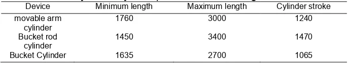
Table 1. Hydraulic cylinder parameters of working device / mm
Device Minimum length Maximum length Cylinder stroke
movable arm cylinder
1760 3000 1240
Bucket rod cylinder
1450 3400 1470
Bucket Cylinder 1635 2700 1065
1-bucket; 2-bucket rod; 3-movable arm; 4-rotary platform; 5-arm hydraulic cylinder; 6- piston rod of movable arm hydraulic cylinder; 7-linkage; 8-bucket linkage; 9- hydraulic cylinder piston rod of bucket; 10-bucket hydraulic cylinder;
11-bucket rod hydraulic cylinder; 12- piston rod of bucket rod hydraulic cylinder.
Figure 1. Simulation Model of working device
3. Theoretical Load Calculation Hydraulic Excavator
When in use,the loads types and its distribution is very complex for hydraulic excavator. Digging load was mainly composed of mining resistance, material weight and working device's own weight. Due to the influence of excavation resistance on the reliability and excavating ability of the working device is significant, so the digging resistance force must be analyzed and calculated. The digging resistance force is usually generated by the combination of the frictional force from bucket cutting soil as well as the cutting and pushing resistance forces from soil [5]. According to the tangential and normal direction from digging trajectory, digging resistance force could be decomposed intotangential and normal direction. Furthermore, it could be approximated to that apply on the bucket tooth tip, the experience formula as [6]:
Tangential digging resistance force:
max 0 max
t t
W
K bh
(1)
Normal digging resistance force:
max max
n t
W
W
(2)
where: is the coefficient of digging specific resistance force (N/mm2), which refers to the resistance force that soil to overcome when dug a unit area of soil. It is a comprehensive reflection of the bucket digging resistance combined.
is the bucket width or digging width (mm).
h
0
K
According to literature [7, 8], the soil type was selected as grade Ⅲ and 2
0 19.5N cm
K , b=120cm, . , =0.42.
The results after calculating are: the tangential and normal digging resistance forces respectively are equal to 56.16KN and 23.59 KN. In practical operation, the digging resistance force not only related to bucket’s shape, friction resistance force between bucket and soil and soil’s cutting resistance force, but also related with the position of hydraulic excavator, the system’s working pressure and the working area of digging hydraulic cylinder piston. So the digging resistance force by 1.5 times was used to check in calculation of the excavating resistance. i.e.
max t
W
=1.5×56.16KN=84.24 KN (3)
n max
W
=1.5×23.59 KN=35.385 KN (4)
The formula for calculating the gravity of the excavated material is:
(5)
Where, is the density of soil with value . x ‐6 kg/m ; is the volume of bucket with value
1.05m3; g is the acceleration of gravity with value . x mm/s. Finally the result of G is equal to 18.5 KN after calculating.
4. Control for Function
Excavator operation is divided into digging, lifting, rotation, unloading, anti-rotation, lowering arm and so forth. The amount of elongation for hydraulic cylinder at different times was actually measured by analyzing various working conditions. Assuming that both the applied forces and amount of elongation for cylinder piston are gradually changing during the operating process of working device for hydraulic excavator, thus the digging resistance force produced by bucket is more complex. So, it is more difficult to completely true describe the bucket’s digging resistance force in its dynamics analysis, forasmuch it is usually instead by using the central concentrated force of bucket tooth.
4.1. Control Foe Drive Function
The hydraulic pressure of hydraulic cylinder is the motive power for working device. In ADAMS, it is needed to apply step function ‘STEP’to drive the hydraulic cylinder. Each drive function for hydraulic cylinder and rotary motion mechanism is set as follows:
(a) The driving equation for the movable arm oil cylinder is defined as:
STEP(time,0,0,0.9,150)+STEP(time,0.9,0,4.6,0)+STEP(time,4.6,0,8.1,-390)+ TEP (time,8.1,0.0,9.1,0.0)+STEP(time,9.1,0.0,12.2,0)+STEP(time,12.2,0.0,13.6,-40)+STEP(time,0.0,15,430)
(b) The driving equation for the bucket rod oil cylinder is defined as:
STEP(time,0,0,0.9,-100)+STEP(time,1,0,4.6,-400)+STEP(time,4.6,0.0,8.1,0)+
STEP(time,8.1,0.0,9.1,0.0)+STEP(time,9.1,0.0,12.2,250)+STEP(time,12.2,0.0,15,150) (c) The driving equation for the bucket oil cylinder is defined as:
STEP(time,0,0,0.9,100)+STEP(time,0.9,0,2,0)+STEP(time,2,0,4.6,-340)+STEP(time, 4.6,0.0,8.1,-150)+STEP(time,8.1,0.0,9.1,0.0)+STEP(time,9.1,0.0,10.3,0.0)+
STEP(time,10.3, 0,12.2,490)+STEP(time,12.2,0.0,15,0.0) (d)The driving equation of the rotary motion pair is defined as:
STEP(time,0,0, 0.9,0)+STEP(time,1.0,0.0, 4.6,0.0)+STEP(time, 4.6,0.0,6.4,0.0) +STEP (time,6.4,0.0,9.1,90d)+STEP(time,9.1,0.0,12.2,0.0)+STEP(time,12.2,0.0,15,-90d)
Figure 2 shows the above four drive function curves for oil cylinder and rotary mechanism.
Figure 2. Drive function curves for oil cylinder and rotary mechanism
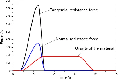
4.2. Load Function Control
According to the calculation results from tangential and normal resistance forces, simulation analysis in the ADAMS described those two kinds of digging resistance formuch functions expressed as follows:
(a) The function of tangential resistance force is:
STEP(time,1.0,0.0,3.6,84240)+STEP(time,3.6,0.0,4.5,- 84240) (b) The function of normal resistance is:
STEP (time,1.0,0.0, 3.6,35385)+STEP(time, 3.6,0.0, 4.5,-35385) (c) The gravity of the material is:
STEP(time,1.0,0.0,4.5,18500)+STEP(time,4.5,0,9.7,0)+STEP(time,9.7,0.0,12,-18500) Figure 3 shows the above three load curves of excavator working device.
Figure 3. Load curves of excavator working device
5. Simulation Analysis
According to the above analysis and calculation, the model of working device for hydraulic excavator is applied various loads in the ADAMS software: the gravity load is vertically downward and the direction keeps constant; the direction of tangential resistance force opposites to that of bucket movement; the direction of normal resistance force is vertical to that of bucket movement and changes with the bucket position changes.
The total simulation time is 15s and simulation step number is 200, where the excavator's preparation time (i.e. the excavator from the down position to enter the digging site) is 1s. The whole process of the operation time is 14s. In the simulation process, the ADAMS automatically calculates the forces for each node to obtain the displacement and load change of
0 3 6 9 12 15
Rotary motion pair oil cylinder
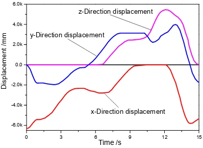
5.1. The Bucket Tooth Displacement Simulation Analysis of Bucket
The Figure 4 shows the displacement simulation curves of bucket teeth tip. As it can be seen from the figure, the displacement of bucket tooth tip is changed under the driving by movement of every hydraulic cylinder and is consistent in the actual work. On the other hand, it also can be seen from the figure that: (a) The hydraulic excavator is at the mining stage during 0~6s, in which the z-direction displacement of bucket tooth tip keeps constant and moving in a vertical plane; (b) The hydraulic excavator is at the rotary stage during 6~10s, in which the x-direction, y-x-direction, z-direction displacement of bucket tooth tip are all constantly changing; (c) The hydraulic excavator is at the stage of rotary ending and unloading beginning until completion during 10~12s, in which the x-direction displacement of bucket tooth tip is a linear curve with invariant; (d) The hydraulic excavator is at the stage of unloading end and return to the beginning place during 12~15s, in which the x-direction, y-direction, z-direction displacement of bucket tooth tip are all constantly changing.
Figure 4. Displacement simulation curves of bucket teeth tip
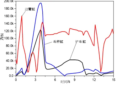
5.2. Force Simulation Analysis of Hydraulic Cylinder
The Figure 5 the force variation simulation curves of movable arm, bucket rod and bucket oil cylinder in the in the process of hydraulic cylinder. As can be seen from Figure 5, hydraulic excavator is at the stage of preparation during 0-1s. Three cylinders work at the same time and force fluctuation is obvious. The stage of the arm movement is mainly in the moving arm with pressure changes greatly; before excavator digging, oil pressure of each hydraulic cylinder dropped to about 5 kN. When bucket began digging, the force applied on bucket rod oil cylinder and bucket cylinder increases along with digging resistance increasing under the combined action of tangential and normal resistance force as well as the gravity of materials. When the digging resistance force is maximum, the force of bucket rod and bucket cylinder reached the maximum value, and then began to decrease. Moving arm cylinder is firstly compressed and soon afterwards is in tension with the increase of digging resistance force; those obviously are consistent with the figure 5. Afterwards working device enter the stage of enhance and rotary, in which it only be subjected to the action of the gravity of materials, so the moving arm cylinder force fluctuations about 120 kN. At the unloading stage, forces of cylinder arm oil cylinder, bucket rod oil cylinder and bucket cylinder are rapidly decrease, especially moving arm cylinder decreases sharply due to the gravity of materials became less. When material unloading stage is completed, bucket rod oil cylinder, bucket cylinder contracted to cause the center of gravity improving and force of movable arm oil cylinder increases. At last, excavator enter into the rotary state, movable arm cylinder needed enhance a distance to the bucket does not collide with its nearby equipment. Next, the movable arm cylinder reached the highest working point,force continued to increasing. Finally the movable arm cylinder ,
contracted and returned to digging site, thus entering into a mining cycle operation. Through simulation analyzing, its results almost match with the actual condition.
0 3 6 9 12 15
-6.0k -4.0k -2.0k 0.0 2.0k 4.0k 6.0k
z-Direction displacement
y-Direction displacement
Di
sp
la
ce
m
ent /m
m
Time /s
0 3 6 9 12 15
Figure 5. Force variation simulation curves of hydraulic cylinder for movable arm, bucket rod and bucket oil cylinder
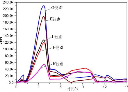
5.3. Force Simulation Analysis of Each Hinge Point for Hydraulic Excavator Working Device
The Figure 6 and Figure 7 respectively show the force variation curves of each joint of movable arm and bucket rod. From the figure it can be seen when mining combined resistance at the maximum in the mining process, constraint forces both for the movable arm and the bucket rod hinge point are at maximum. When at 3.6s, bucket rod cylinder pressure becomes a maximum value about 190 kN under the interaction of bucket rod and bucket hydraulic cylinder,which is in line with the actual situation. When digging resistance force becomes maximum, the maximum constraint force appears at the hinged point between the movable arm and the bucket rod. Therefore, between the movable arm and the bucket rod is the easy damaged part in mining process. So, it should be fully considered the influence of strength and stiffness in the calculation of structure design. In addition, the movable arm and the platform hinge point A is easy to damage. Under the maximum unloading radius, those hinged points not only bear the weight of the working device, but also by the centrifugal force of the working device and rotary inertia force along with the bending stress is large. The connecting shaft of the movable arm and the bucket rod hinged point should select with the high strength alloy steel, and the surface is specially treated to improve the fatigue strength and prolong the service life.
0 3 6 9 12 15
0 3 6 9 12 15
Figure 7. Force variation curves of each joint of bucket rod
6. Conclusion
(1) By determining the spatial position relation of hydraulic excavator's working device, its 3D model was established by parametric design software Pro/E and then imported into simulation analysis software. Material properties and constraints are imposed to establish the virtual prototype model, and then the analyses of whole working cycle were simulated for hydraulic excavator. Simulation results show that there are no component interference phenomenon appeared, proving that modeling and imposed constraints are exactly right.
(2) Combined Pro/E software and ADAMS software, the simulation model of excavator working device was established so that improve the excavator working device size accuracy and precision assembly, providing a more intuitive and convenient way for the modification and simulation of hydraulic excavator working device components and model.
(3) The comparison between the simulation results and the actual working conditions of the excavator is in good agreement, which indicates that the model can provide reference for the further design and optimization of the excavator working device.
(4) During the working process of the excavator, the maximum load appears in the digging resistance, and the resistance is proportional to the load. The maximum value of the dynamic arm is about 190 kN.
(5) Through the dynamic simulation analysis of excavator working device, the design quality of the excavator working device is very important.
Acknowledgements
This research was A Project Supported by Scientific Research Fund of Hunan Provincial Education Department (No.15C1240).
References
[1] Zweiri YH, Seneviratne LD, Althoefer K. A generalized Newton method for identification of closed-chain excavator arm parameters. New York: International Conference on Robotics and Automation. 2003; 34(2): 103−108.
[2] Santoso DR, Maryanto S, Nadhir A. Application of Single MEMS-accelerometer to Measure 3-axis Vibrations and 2-axis Tilt-Angle Simultaneously. TELKOMNIKA (Telecommunication Computing Electronics and Control). 2015; 13(2): 442-450.
[3] Xu LC. Modeling and Simulation for the Drivetrain of Reversal Stubble-breaking Rototiller Based on SolidWorks and ADAMS. TELKOMNIKA Indonesian Journal of Electrical Engineering. 2013; 12(3): 1850-1854.
[4] Peng BS. Prospect of overseas and domestic extra large hydraulic excavators. Construction Machinery Technology & Management. 2008; (9): 37−38.
[6] T Sutikno, M Facta, GRA Markadeh. Progress in Artificial Intelligence Techniques: from Brain to Emotion. TELKOMNIKA (Telecommunication Computing Electronics and Control). 2011; 9(2): 201-202.
[7] Tian J. Study on Control Strategy of Electro-Hydraulic Servo Loading System. TELKOMNIKA Indonesian Journal of Electrical Engineering. 2012; 11(9): 5044-5047.