4 BASES SMART BED PROTOTYPE WITH MULTIPLE LOAD SENSING TO CONTROL THE SLOPE OF MULTIPLE BASES USING SERVO MOTOR
CONCEIVED AS A CONDITION OF COMPLETING STRATA STUDIES PROGRAM AT THE DEPARTMENT OF ELECTRICAL ENGINEERING, FACULTY OF ENGINEERING
BY
REYAD R.M.SEDER D400144006
ELECTRICAL ENGINEERING, STUDY PROGRAM OF ENGINEERING UNIVERSITAS MUHAMMADIYAH SURAKARTA
4 BASES SMART BED PROTOTYPE WITH MULTIPLE LOAD SENSING TO CONTROL THE SLOPE OF MULTIPLE BASES USING SERVO MOTOR
Reyad R.M. Seder
Department of Electrical Engineering, Universitas Muhammadiyah Surakarta Jl. A. Yani Drum Pos 1 Pabelan Kartasura. April 2017
Email: [email protected]
Abstract
The focus of this paper is to create an intelligent system that allows the use and development of a bed prototype to change the outlook received into the sleeping bed, as this system can improve the perspective used in the regular bed or even the hospital user at present time, where it allows the movement of a limited number of limbs only, while it does not help patients or nurses to change the sleeping position of the patient, which will affect un the physical and vital healthy, so that prototype bed system was established to move the whole body to simplify movement, which facilitates the work of nurses and the patient to reduce the percentage of ulcers the result of long sleep in one position. The proposed platform collects information from various sensors incorporated into the bed, analyzes the data to create a time-stamped, whole-bed weight distribution map, and commands the bed’s actuators to periodically adjust its surface profile to redistribute pressure over the entire body. These capabilities are combined to a form cognitive support system, for proof of concept, we have implemented algorithms and architectures that cover four key aspects of this platform: 1) data collection, 2) modeling & profiling, 3) a smart machine, and 4) acting.
In this prototype the essence of making a system more smarter, by how to control the adjustment of servo motor to make the changes in the bed surface either manually or automatically, where the value that came from the load cell it will be used to defined the degree of servo in the Arduino program, on one hand to use the manual control will be commanded by re adjusting the potentiometer from (0 to 90)degree, On the other hand coupling the reading of load cell with the degrees of servo motor to control the base that mean the data came from the load cell will be used with the adjustment of base slope. Moreover it will be use a four bases of acrylic, to distribute the entire body on the surface, for measure and show how the sensor and actuator works, as well to give the best reaction to the automatic system and the most attention to the patient for any detection, because every position on the top of the surface will be followed with deferent reaction, while that the LCD keep monitoring each load cell used and each measurement of each part.
Keywords: smart system, load cell, Arduino, servo motor, slope base.
Abstrak
menyederhanakan gerakan, yang memfasilitasi pekerjaan perawat dan pasien untuk mengurangi persentase borok hasil tidur panjang di satu posisi. Platform ini diusulkan mengumpulkan informasi dari berbagai sensor dimasukkan ke dalam tempat tidur, menganalisis data untuk membuat, seluruh tempat tidur peta distribusi berat waktu dicap, dan perintah aktuator tempat tidur untuk secara berkala menyesuaikan profil permukaan untuk mendistribusikan tekanan di seluruh tubuh. Kemampuan ini digabungkan untuk bentuk sistem pendukung kognitif, untuk bukti dari konsep, kami telah mengimplementasikan algoritma dan arsitektur yang mencakup empat aspek kunci dari platform ini: 1) pengumpulan data, 2) pemodelan & profiling, 3) mesin cerdas, dan 4 ) akting.
Dalam prototipe ini esensi dari membuat sistem yang lebih pintar, dengan cara mengontrol penyesuaian motor servo untuk membuat perubahan di permukaan tidur secara manual atau otomatis, dimana nilai yang datang dari sel beban itu akan digunakan untuk mendefinisikan tingkat servo dalam program Arduino, di satu sisi untuk menggunakan kontrol manual akan diperintahkan oleh ulang menyesuaikan potensiometer dari (0 sampai 90) derajat, di sisi lain kopling pembacaan load cell dengan derajat motor servo untuk mengontrol dasar yang berarti data berasal dari sel beban akan digunakan dengan penyesuaian kemiringan dasar. Selain itu akan menggunakan empat dasar akrilik, untuk mendistribusikan seluruh tubuh di permukaan, untuk mengukur dan menunjukkan bagaimana sensor dan aktuator karya, serta memberikan reaksi terbaik dengan sistem otomatis dan perhatian yang besar kepada pasien untuk setiap deteksi, karena setiap posisi di atas permukaan akan diikuti dengan reaksi relatif kecil, sementara bahwa LCD terus memantau setiap sel beban digunakan dan setiap pengukuran masing-masing bagian.
Kata kunci: sistem cerdas, load cell, Arduino, motor servo, dasar lereng.
1. Introduction
Major progress has taken place in the field of information and communications technology (ICT) usage in learning environments. The advantages offered by ICT, in this sector have led most educational institutions to integrate ICT services into their departments. Scientists are working very hard to provide an advanced technology, which can benefit them in many areas. Smart system and creating a new generation of smart equipment is one of the most creative of these solutions. If we take a look around us nowadays we will see everything is going faster and getting smarter. Because the human never stop to improve and increase the knowledge of the machine, so on we like it, and we keep always looking for such things to make our life faster and easier.
potentially offer a practical approach to on-bed body movement monitoring(Musaab Alaziz). But actually when we replace a load cell under all the body it will give us more efficiency and performance, so on it will easily detect any changes in that weight, because any movement for the body on that surface it will give deferent concept to the sensors, as well we believe that load cells could potentially offer a practical approach to on-bed body movement monitoring and efficiency adjustment.
For measuring weight, accuracy is the most important. The use of sensor is one of the solutions to make digitized. Where load cell is expected to be implemented as a new method for narrow weight measuring device. This paper shows where the surface of the bed is connected to load cell to detect the changes in the body weight, then converted it into electrical signals which processed and displayed by a microcontroller system, for using this data later of any effect in the bed surfaces, moreover these changes it will effect on a servo motor to adjust the slope of bed surface.
Vital signs monitoring during the night is essential for health assessment and patient monitoring (Waltisberg, 2014). On the other hand the improvement of the real-time response of a load cell used to carry out the measurement of tension forces applied horizontally to the mechanical structure of a smart bed, then get that effect for make any person get the rest and change their position on the surface of the bed with manually or automatically changes.
2. Theory
People always need intensive care, which in turn helps to improve health, but at the same time, such work strain nurses, because in some cases the patient needs a lot of movement to keep his body free of ulcers and pain, which causes sleep For a long time on one side of the body, however, most of the time a new beds system is built, which is based on moving the limbs only without attention or taking a look at the middle side of the body.
Overall the measurement of patient movement can be used to determine whether that movement has been so limited over a period of time that the patient must be turned to a new position by a health care professional to prevent the occurrence or exacerbation of pressure or bed sores (Spillman 2004).
Thus, the creation of a new idea of the beds which is based on the principle of moving the entire body, and not only from one side, but from several different position, it may contribute to the development of a new concept and idea in the work of development, as this will help the patient to reduce these ulcers at the same time Which will help hospital workers reduce these efforts, for example when a nurse needs to move the left or right part of the patient's body, so he needs to carry the patient and change his position manually, while he can do such a performance with the help of the machine.
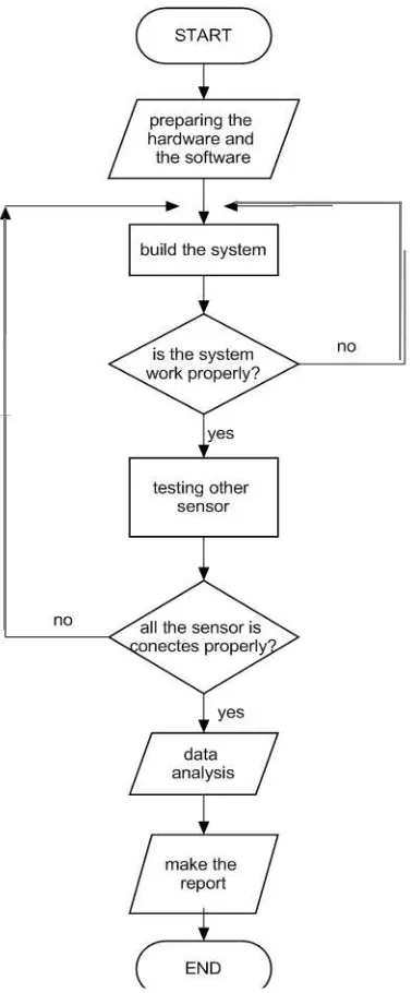
3. Overview of system flow
or with any related device, so for make the project more interesting it can to connect it to android device or to excel data base. If the testing is failed, the device need to be repaired, for this it can fix the error using the feedback that the program or the project made, then re-test. But if the testing gives the proper result then it can continue. Posteriorly the device will be used to measure the changes and the results will be analyzed, then write it into the report and article.
Figure 1. Flowchart of Research
4. Device System
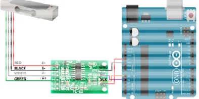
Figure 2 is a block diagram of a load cell amplifier, it is a small breakout board that allow the system to easily read the load cell to measure the weight by connecting the amplifier to the Arduino then it will be able to read the changes in the resistance of the load cell, then with some calibration the Arduino will be able to get every accurate
weight measurement, on other way the load cell is connected as Wheatstone bridge with the ADC (analog to digital converter), then the circuit connected to Arduino mega board
Figure 2. Wheatstone bridge as load cell connected with HX711
In figure 3 is other way to show the HX711 component, with the main part of it, for give more knowledge and information to the reader. Where the whetstone or in other sentence load cell is about an electrical circuit it used to measure an unknown electrical resistance by balancing two legs of a bridge circuit, one leg of which includes the unknown component. The primary benefit of a whetstone bridge is its ability to provide extremely accurate measurements.
Figure 3. Load cell with HX711 circuit
In Figure (4, 5.a) It show the project image, where it uses one load cell as the main part of the project fastener with Acrylic base on the top of it, and all of the load cell dimension as figure 5 is fixative up to wood board as it figured in figure 9 then it connected with Arduino board for programing the system and control it depend on some codes and formula, after all the Arduino board connected to LCD model for showing the weight and the calculation to the users.
Figure 4. Load cell with the Arduino Mega
LCD 16*2
HX711 Arduino
Load Cell
Figure 5.a Block Diagram One Circuit
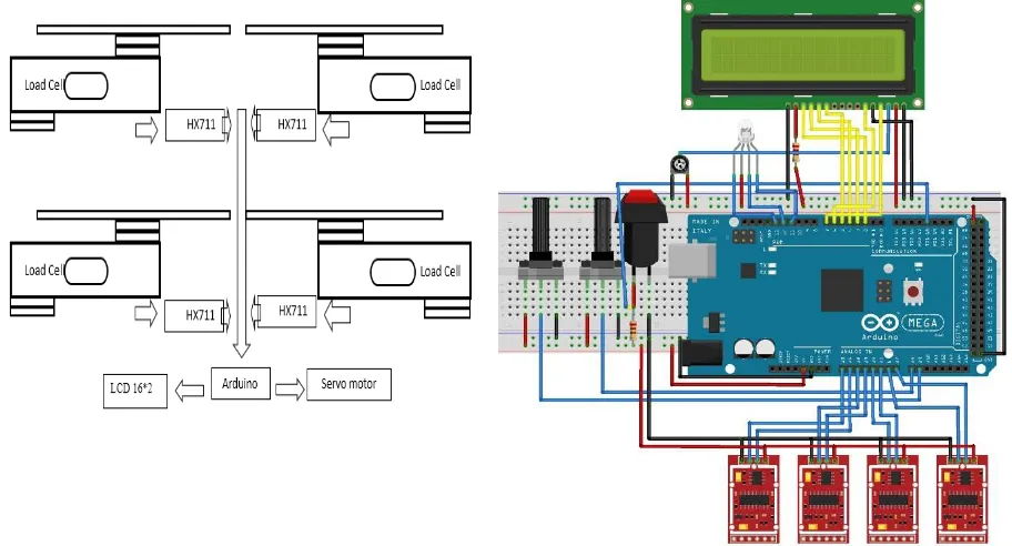
In figure (5.b, 5.c) is showing the full diagram and schematic of the full system and how it is connected to the microcontroller (Arduino mega 2560), it is showing each pin and the main component that it used for this research, As it enables researchers to know all the links and details of this research, through which can develop and provide the legislator with new ideas.
Figure 5.b schematic Circuit all the system Figure 5.c Block Diagram Circuit all the system
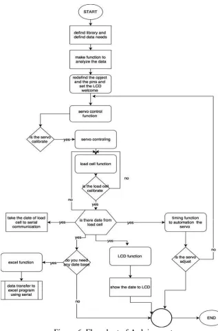
5. Arduino system
Figure 6. Flowchart of Arduino system
6. Device Dimension
On the other hand, the servo motor, where it is the (sg90 micro servo), Tiny and lightweight with high output power. Servo can rotate approximately 180 degrees (90 in each direction), and works just like the standard kinds but smaller, it is connected to the digital pin of Arduino board.
Continuing to the box again, and the push button where it used to flip the system between the manual and the automatic system, well it uses the Arduino digital pin but this time with interrupt pins, because the system is too large, and the Arduino code is so long so it makes faster and easier to flip between both of it.
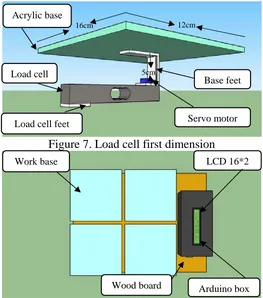
Figure 7. Load cell first dimension
Figure 8. Explain the view of the system on the board with the Arduino box and the LCD without the servo motor
Figure 9. Side view for all the system
Load cell
Base feet Acrylic base
Load cell feet
Servo motor
Work base LCD 16*2
Arduino box Wood board
Arduino board Servo with load cell
12cm 16cm
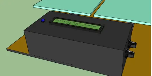
Figure 10. Arduino box and the LCD with potentiometer and the push button
Figure 11. Top side view of load cell on the board with the Arduino box and the LCD
7. Forms of Calculations
7.1. Weight Calculation
There is deferent calculation of this program, and that depend on which load cell the going to use, but the main formulas for all of the calculation of it.
With one or average of these data calculate the value of the scale that it uses the following formula:
scale the serial value scale the real value … … … …
The value of the weight must be in the units, which the balance to work, for example it could be 4Kg or 4000g for Kilograms or grams respectively.
Then the value of the Scale that used is:
scale 7 77 … … … …
scale = 439430.25
With this data already obtained start to program the sketch that are going to use weigh, and it have to change the value of the program code with this value.
scale.set_scale(439430.25); //constant calibration.
Where in this programing code it has to set the constant calibration that it founded in the previous scale formula.
(scale.get_units(),3)
8. THE RESULT AND ANALYSIS 7.1 Automatic system analyze
Table 1. Description of automatic system
Base Number 1 2 3 4
System Description Figure………….. . Description co nd itio n
degree(º) Time(s) co
nd
itio
n
degree(º) Time(s) co
nd
itio
n
degree(º) Time(s) co
nd
itio
n
degree(º) Time(s)
Raise up ↗ Sit down ↙
Figure First position
Equal Base (1 = 4 , 2 = 3)
↗ 30 1 ↗ 30 1 - - - This position move
equaly in both side, (Left-Right ) after the atumatic control activate.
↗ 60 1 ↗ 60 1 - - - -
↙ 30 1 ↙ 30 1 - - - -
↙ 0 1 ↙ 0 1 - - - - - -
- - - - - - ↗ 30 1 ↗ 30 1
- - - - - - ↗ 60 1 ↗ 60 1
- - - - - - ↙ 30 1 ↙ 30 1
- - - - - - ↙ 0 1 ↙ 0 1
Figure Second position
Large A Base (1 > 4 , 2 > 3)
↗ 30 1 ↗ 30 1 - - - this will effect on the
left side to rais it up.
↗ 60 1 ↗ 60 1 - - - -
↙ 30 1 ↙ 30 1 - - - -
↙ 0 1 ↙ 0 1 - - - - - -
Figure Second position
Large B Base (1 < 4 , 2 < 3 )
- - - - - - ↗ 30 1 ↗ 30 1 this will effect on the
right side to rais it up.
- - - - - - ↗ 60 1 ↗ 60 1
- - - - - - ↙ 30 1 ↙ 30 1
- - - - - - ↙ 0 1 ↙ 0 1
Figure Third position
Slope A (1 > 4 , 2 < 3 )
- - - ↗ 30 1 - - - ↗ 30 1 this will effect on the
base number(2,4) to rais it up.
- - - ↗ 60 1 - - - ↗ 60 1
- - - ↙ 30 1 - - - ↙ 30 1
- - - ↙ 0 1 - - - ↙ 0 1
Figure Third position
Slope B (1 < 4 , 2 > 3 )
↗ 30 1 - - - ↗ 30 1 - - - this will effect on the
base number(1,3) to rais it up.
↗ 60 1 - - - ↗ 60 1 - - -
↙ 30 1 - - - ↙ 30 1 - - -
↙ 0 1 - - - ↙ 0 1 - - -
Figure fourth position
baby A (1 > 4 , 2 = 3 )
↗ 30 1 - - - this will effect on the
base number(1) to rais it up.
↗ 60 1 - - - - - - - - -
↙ 30 1 - - - - - - - - -
↙ 0 1 - - - - - - - - -
Figure fourth position
baby B (1 = 4 , 2 > 3)
- - - ↗ 30 1 - - - this will effect on the
base number(2) to rais it up.
- - - ↗ 60 1 - - - -
- - - ↙ 30 1 - - - -
- - - ↙ 0 1 - - - - - -
Figure fourth position
baby C (1 = 4 , 2 < 3 )
- - - - - - ↗ 30 1 - - - this will effect on the
base number(3) to rais it up.
- - - - - - ↗ 60 1 - - -
- - - - - - ↙ 30 1 - - -
- - - - - - ↙ 0 1 - - -
Figure fourth position
baby D (1 < 4 , 2 = 3)
- - - - - - - - - ↗ 30 1 this will effect on the
base number(4) to rais it up.
- - - - - - - - - ↗ 60 1
- - - - - - - - - ↙ 30 1
- - - - - - - - - ↙ 0 1
In table 1 is the description of each step after activate the automatic system, and it show how the base will act based on the body weight, and position on the surface. For example as in First position where the base take the read from the load cell as each opposite base is equal in weight, so base number 1 is equally to base number 4, as well base number 2 is equally with base number 3. When this condition is correct the base number (1 and 2) will react together and it will give signal to the servo motor that raise up the base for 30 degree for one second, then raise it once again for 30 degree more to be as 60 degree, after that the load cell will send another signal to sit the base down with 30 degree and 30 degree again to be as the 0 degree. Forward to that the opposite base will act the same where in this time base number (3 and 4) will take the signal together and make the reaction together so it will raise up 30 degree and 30 again, and when sit the base down it will react the same so it will set 30 degree and 30 degree again for each raise up or sit down it will take 1 second because the delay of the system made for 1 second only but actually we can manage the degree and the delay time from the Arduino program to be faster or slower, larger or smaller.
7.2 Excel data base analyze and description
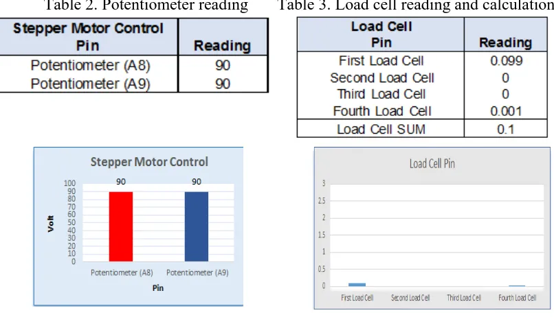
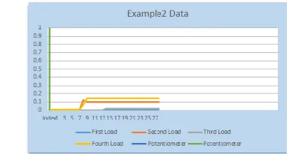
Table (2-4) and figure (12-14) is showing the data and the chart, which it came from the excel data base, that it give a look at what is happening in the program systems and matrices, as well as through it which can know the differences in the Arduino program and all types of sensors, in one hand these tables and figure are deferent in time as showed in both table (4, 7) ,on the other hand it showed deferent reading in deferent pins inside Arduino board, such of these differences are table (2, 5 and 3, 6) where it show the deferent value for each of the load cell , or the potentiometer in deferent time.
Table 2. Potentiometer reading Table 3. Load cell reading and calculation
Figure 12. Potentiometer reading chart Figure 13. Load cell reading chart
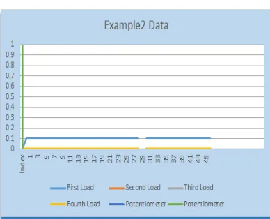
ble 4. Excel data description
Figure 14. Data reading chart
These tables show the reading value of each deferent sensor and deferent reading in potentiometers, in case to know which load cell is active, and work effectively with less possible of error. Well in table (5, 6) it is display the direct reading values for each sensor and value with the summation of the total load cell, but in table 7 it is showing the total reading with the date and time, and this what it call the data base, because it keep the values in the system and excretion it any time or date. Further the figure (14 – 16) as same as the figure (12 – 14) for the reading chart of each table in the Excel program. That allow the user to know the fast deferent reading without take a look to the table.
Table 5. Potentiometer reading Table 6. Load cell reading and calculation
Figure 14. Potentiometer reading chart Figure 15. Load cell reading chart Table 7. Excel data description
Load Cell
Pin Reading
First Load Cell 0 Second Load Cell 0.101
Figure 16. Data reading chart
9. CONCLUSIONS AND SUGGESTIONS
8.1 Conclusions
There are many prototypes. As the underlying technologies, further development, and for improve the knowledge around the world, it must keep try to make the best. To make the world smarter and more effective in the future, we have to generate many kind of prototype and devices, which are of material or moral benefit.
1. This paper show the applied and Design of a smart bed prototype that will control surface to get the most valuable result in human pain and sore, where it use the mechanical intelligence to control a servo motor depend on the values that it return from load cell sensor in automatic system, and the potentiometer in manual one, for change the slope of the prototype surface. 2. As well in this paper designing a method can contribute positively to achieve
the gap between intelligent signal processing and the design of intelligent sensors for smart bed, where the using of load cell allows to know the deferent in position for the body on the surface.
3. The challenge in this prototype will appear when the controlling of servo motor effect on the base to give the most valuable result. When the deferent reading for the sensor value give data that it used in the program to adjust the automatic system for the servo motor as well in base propensity.
8.2 Suggestions
The results of this research are still far from perfection, it needs to be developed further, with some consideration for the following improvements:
1. This research is still very simple, so it need Methods to put the point and get the top reaction, not only based on the assumption of load cell but other kind of motors, as well it is necessary to develop other methods to obtain the better point.
2. It need more improvement by using other kind of sensor, and other way of controlling system.
3. This research used to control automatically but is still need to be smarter by using other controlling system such as a smart phone or re adjust it using a computer program.
4. Need to research another method to get a better, so that all surfaces can be reconstructed, including better model and depth of the curve of the reliefs. 5. This system still as a prototype and it needs to take it to the reality, so it need a
10.Acknowledgments
I am very thankful to Allah, by His help, that I can finish this final project .Thanks to my parents, who always providing me the best supporting and keep praying me for success in my life and study.
This proposal was supported by the startup package of journal and the internet research by Reyad R.M. Seder. I would like to thanks Mr. PhD Dedi Ari Prasetya (University Muhammadiyah Surakarta) my supervisor, by his guide, I enjoy doing my final project because of his credebility being a great lecturer. As well all the lecturers of the (University Muhammadiyah Surakarta) for their contributions to implementation of the algorithm in my proposal. Thanks to my Friend for helping and supporting me for making my project.
11.Reference
Franklin Avenue Tustin. 14192, SMART LOAD CELL SYSTEMS, Revere Transducers Inc,
CA 92780-7016, U.S.A. Http://www.reveretransducers.com.
W B Spillman, M Mayer, J Bennett, J Gong, K E Meissner, B Davis, R O Claus, A
Muelenaer Jr and X Xu1, A 'smart' bed for non-intrusive monitoring of patient
physiological factors Article in Measurement Science and Technology . · July 2004.
,Musaab Alaziz, Zhenhua Jia, Jian Liu, Richard Howard, Yingying Chen, and Yanyong
Zhang, MotionScale: A Body Motion Monitoring System Using Bed-Mounted
Wireless Load Cells ,Rutgers University 2Stevens Institute of Technology 1musaab,
zhenhua, reh, [email protected].
Wilmar Hernandez, Improving the Response of a Load Cell by Using Optimal Filtering,
Department of Circuits and Systems in the EUIT de Telecomunicacion at the
Universidad Politecnica de Madrid (UPM). 21 July 2006.
Daniel Waltisberg, Oliver Amft, Gerhard Tr¨ oster, Accuracy-Coverage Tradeoff of
Nocturnal Vital Sign Estimation in Smart Beds, ¨ urich [email protected].
UBICOMP '14 ADJUNCT, SEPTEMBER 13 - 17, 2014, SEATTLE, WA, USA.
Yousefi1, S. Ostadabbas, M. Faezipour, M. Nourani1, A. Bowling, D. Behan and M.
Pompeo, A Smart Bed Platform for Monitoring & Ulcer Prevention R. 2011 4th