i
DEVELOPMENT OF SECURE WATER FILTER
KHAIRUL AMAR BIN KHAIRULLAIL
A thesis in partial fulfilments of requirements for the award of the degree of
Bachelor of Electronic Communication Engineering
Faculty of Electronics and Computer Engineering
UNIVERSITI TEKNIKAL MALAYSIA MELAKA (UTeM)
v
“Specially dedicated to my beloved parents, brothers, sister,
lecturer and friends who have encouraged, guided and inspired
vi
ACKNOWLEDGEMENT
First of all, I want to praise to Allah S.W.T because give strength to finish this final year project report successfully. I also would like to take this opportunity to express my deepest gratitude to my project supervisor, Dr Zamre Bin Abd Ghani who has persistently and determinedly assisted me during the whole course of this final year project. It would have been very difficult to complete this project without the enthusiastic support, insight, cooperation and advice by her.
vii
ABSTRACT
viii
ABSTRAK
ix
TABLE OF CONTENTS
CHAPTER TITLE PAGES
PROJECT TITLE i
REPORT STATUS VERIFICATION FORM ii
STUDENT’S DECLARATION iii
SUPERVISOR DECLARATION FORM iv
DEDICATION v
1.2 PROJECT OBJECTIVES 2-3
1.3 PROBLEM STATEMENT 3-4
2.1 CHAPTER OVERVIEW 11-12
2.2 PREVIOUS PROJECT 12
x
PURPOSES WATER FILTER SYSTEM
2.2.2 DESIGN AND FABRICATION OF LIQUID 13-14 DISPENSING MACHINE USING AUTOMATIC
CONTROL FOR ENGINEERING INDUSTRY
2.2.3 TESTING AND PERFORMANCE 15 ANALYSIS ON AIR CONDITIONER
CUM WATER DISPENSER
2.3 HARDWARE 16
2.3.1 WATER FILTER/WATER PURIFICATION 16
2.3.2 RELAY 17-19
2.3.3 7 SEGMENT DISPLAY 19-20 2.3.4 WATER PAD DETECTOR 20-21 2.3.5 PIC MICROCONTROLLER 21-22 2.3.6 LIGHT EMITTING DIODE (LED) 22-23
2.3.7 BUZZER 23-24
2.4 SOFTWARE 24
2.4.1 PROTEUS DESIGN SUITE 24-25 2.4.2 LDMICRO SOFTWARE 25-26
III METHODOLOGY 27
3.1 INTRODUCTION 27
3.2 PROJECT IMPLMENTATION 28
3.2.1 FLOW CHART 1 28-29
3.2.2 FLOW CHART 2 30-31
3.2.3 FLOW CHART 3 31-32
3.2.4 BLOCK DIAGRAM OF WATER PROCESSING 32-33 3.2.5 BLOCK DIAGRAM OF SYSTEM PROCESSING 33 3.3 PROCESS OF PREPARING PROJECT FOR PCB CIRCUIT 34 3.3.1 PREPARATION OF PRINTED CIRCUIT BOARDS 34 3.3.2 ETCHING PROCESS 34-37
3.3.3 DRILL PROCESS 37-39
3.3.4 CIRCUIT TRACING 40
3.3.5 SOLDERING PROCESS 41-42 3.3.5.1 SOLDERING METHOD 42 3.3.5.2 SECURITY MEASURES DURING THE 43
xi
3.3.5.3 REMOVE THE COMPONENT LEGS STEP 43
3.3.6 TEST CIRCUIT 44
3.4 PROCESS OF PREPARING PROJECT FOR STRUCTURE 44 AND MECHANICAL WORK
3.4.1 CONSTRUCT THE BODY STRUCTURE 44-48 OF SECURE WATER FILTER
IV RESULT AND DISCUSSION 50
4.1 INTRODUCTION 50-51
4.2 TESTING AND OUTPUT RESULT 51
4.2.3 SIMULATION CIRCUIT 55 4.2.3.1 COUNTER CIRCUIT 55-56 4.2.3.2 HIGH AND LOW WATER 56-57
LEVEL SENSOR CIRCUIT
4.2.4 ETCHING AND SOLDERING PROCESS 57-58 4.2.5 WATER SENSOR PAD DESIGN 59 4.3 COUNTER CIRCUIT WHEN COUNTING THE CUPS 59-61 4.4 HIGH AND LOW WATER LEVEL SENSOR CIRCUIT 62-65
OPERATION
4.5 PROTOTYPE OF SECURE WATER FILTER 65-67
4.6 DISCUSSIONS 68-69
V CONCLUSIONS AND RECOMMENDATIONS 70
5.1 INTRODUCTION 70
5.2 CONCLUSION 71-72
5.3 ACHIEVEMENTS 72
xii
REFERENCES 77
APPENDIX A 78
xiii
LIST OF TABLES
NO TITLE PAGE
xiv
2.3.1.1 Water Filter/Water Purification 15
2.3.2.1 Shows a Relay 17
2.4.2.1 Counter Circuit with PIC Microcontroller 26
3.2.1.1 Flow Chart for part 1 28
3.2.2.1 Flow Chart for part 2 30
3.2.3.1 Flow Chart 3 31
3.2.4.1 Block diagram of water processing 32 3.2.4.2 Block diagram of system processing 33 3.3.2.1 Protection layer was removed from PCB board 34 3.3.2.2 Placing board with PCB layout in UV machine 35
xv 3.3.2.4 Immersing the board in the developer liquid 36
3.3.2.5 Rinsing board with water 36
3.3.2.6 Placing board into conveyer spray processor 37 3.3.3.1 Drilling process by using drill machine 38 3.3.3.2 Drilling the PCB by using manual drill 38 3.3.3.3 The hole to place the component (bottom side) 39 3.3.3.4 The hole to place components (top side) 39 3.3.4.1 Circuit tracing process to checking the condition 40
of the line circuit
3.3.5.1 Soldering process technique 41 3.3.5.2 The connection of wire during soldering process 41 3.3.5.3 The condition of circuit after soldering process 41
3.3.5.1.1 Soldering iron 42
3.4.1.1 The aluminium structure 45
3.4.1.2 The body structure with the plywood 45 3.4.1.3 Measuring tape is used to measure the parameter 46
of the measurements
3.4.1.4 The hold which made for holding the water dispenser 46 3.4.1.5 Drilling process by using drill machine 47 3.4.1.6 Shellac process to protect the plywood 47 3.4.1.7 Drying process after shellac process 48 3.4.1.8 The condition of the secure water filter after 48
finish structure process
4.2.1.1 Design the hardware of water filter 51 4.2.1.2 The structure of combination of water filter and 52
water dispenser
4.2.2.1.1 Connection of the counter circuit 52 4.2.2.2.1 The connection of the circuit 53 4.2.2.2.2 High and Low Water level Sensor 54 4.2.3.1.1 The connection of the counter circuit between 55
the 7 segment display and the PIC by using ISIS software 4.2.3.2.1 The connection of the high and low water level 56
xvi 4.2.3.2.2 The connection of high and low water level 57
sensor circuit by using ARES software
4.2.4.1 The condition of circuit after etching and 57 drilled process for component pins
4.2.4.2 The condition of circuit after soldering process 58 4.2.5.1 The water sensor pad design 59 4.4.5 High and Low water level sensor in unsafe condition 64 4.4.6 The LED as warning indicator is turn ON 65 5.4.1 Example of the automatic control water valve 73
for the washing machine system
1
1 CHAPTER 1
INTRODUCTION
1.1 Background Project
2
2
Therefore, this product will make three types of production water that have a different taps of water such as hot water, warm water and normal water. Unlike product that is present in market that only produce cold water and hot water especially for water dispensers. With this product that will produce later, it starts by including water from pipe that are used as water sources which that connected directly to filter and consequently enter major tank. The water level inside the major tank will be controlled by the using the mechanical system which are called as float system. It contains clear and clean water before consumers use this water. Water from major tank that clean go to that has been divided into three small water tanks to produce the water in different temperatures. At the major tank were consists of 2 types of sensors which are functionally as the security system where are used to detect the leaking or overflow of the water. The circuit will be connected to prevent the electrical and electronic circuit from any damage that are caused by the water.
From water release, this product is use three types of water valve that were functioning to release the water when the consumers push one of the valves. The valves of water outlet are connected with the tank itself such as is a valve for hot water as connected with the hot tank. In addition, this project also developed with the system of cup counting which is operation to detect a number of cup available in this system. The cups will be provided by the person in-charge (vendors) or any consumers which can be used to take the water production. ‘Secure Water Filter’ this designed especially for consumers as use at home, workers in office that like to drink with ways that is safe and simplest. Through produce hot water, all users can make drink like coffee, tea and other drink easily.
1.2 Project Objectives
The objectives of this project are covered such as
3
3
To develop circuit that can determines the number of cups available inside the system.
1.3 Problem Statement
As the time moves the life style of the person has completely changed and there is no time for the people to have micro management of every issue personally. So, this is the right time to provide some space to the new technology into the live monitoring the issues which are requires the new technology development to make the life mores easier. In the market place, a lot of types of water dispenser and water filter have been sold in the marketing with the different design and structure. Each design was constructed by the company to fulfil the customer’s requirements and beside follow the characteristics or criteria which are appointed by the Ministry of Health Malaysia and Ministry of Commerce and Customers Affairs Malaysia especially for water filter. Water Filter must be able to produce clean and safe water which can be drink by the human without effect the health of the human and also must be approved by SIRIM.
4
4
The high level water circuit and low level water circuit which are operation as the safety circuit contains of the sensors pad as function to detect the water leaking. This sensor will be detect if any leaking out from the tank and once the water leaking, the buzzer and LED as the indicators will turn ON and tell that there are something wrong with the system. In addition, from the water filter dispenser, user must bring the own cup for drinking. So these problems make the user to find the cup first before drink. In this project was provided the cups space which is develop with the circuit or system that can count the number of cup available. With the system, the user can know the total cups available at the 7 segment display and can be add the polystyrene or plastics cups into the space provided.
1.4 Scope of Project
In order to achieve the objectives of this project, scope of work had been divided into two parts which is software and hardware. The hardware work was covered with mechanical work, electrical work and electronic work which are combines together to design the product successfully. In electronics work, before the fabricating process, the circuit that had been designed will be simulating using the suitable software. In this project, Proteus 7 Professional software, Multisim Software and Live-Wire software had been used to simulate the circuit that has been designed and also can be used extensively in a hardware design. For the hardware part, the circuit designed will go through the fabrication process and make sure the connection between the components must be correct.
5
5
correctly and not exposed to any damage especially water. The wiring of circuit must be tidy and orderly to make sure the system is safe. The electrical wiring is provided for the wiring of the heater which is used to boil the water for the hot water tank.
In this project, software is analyzed using assembly to assemble 7 segment displays and sensor. The suitable coding was analyzed to be burned in Peripheral Interface Controller (PIC) by using the LD-micro software. The sensor and 7 segment displays were analyzed according to functionality of this project. Lastly, the scope of the project also must be covered by the following:
• Water source will be processed and divided into three small tanks to store water temperature in normal water, warm water and hot water.
• Water was filtered by anti-dust filter and anti-chlorine filter before supplied into the major tank water.
• Water can refill automatically into the major tank by using the float system as the mechanical concept.
• If water at major tank empty or overflow the sensor pad will be detect, so the buzzer and LED on. This system is used as the secure system to indicate the consumers about the danger and problem of the products, thus the operation of the product must be turns off immediately.
• Count the cup which are available that is able to be used from 0 to 20
1.5 Project Methodology
6
6
prototype of the product also can be designed from the process besides easier to detect the problem of the system quickly if any problem happened.
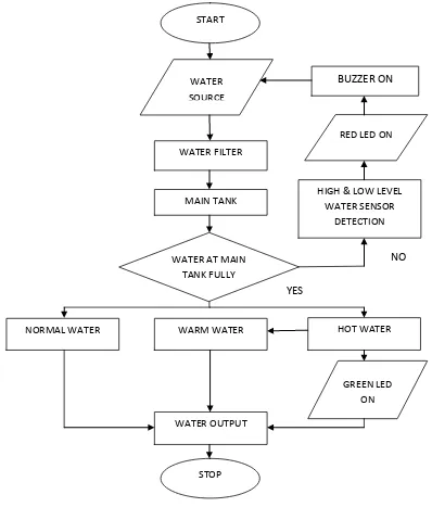
1.5.1 Flow Chart of Secure Water Filter
Figure 1.5.1: Flow Chart of the Secure Water Filter START
WATER SOURCE
WATER FILTER
MAIN TANK
WATER AT MAIN TANK FULLY
NORMAL WATER WARM WATER HOT WATER
GREEN LED ON
WATER OUTPUT
STOP
HIGH & LOW LEVEL WATER SENSOR
DETECTION RED LED ON BUZZER ON
YES
7
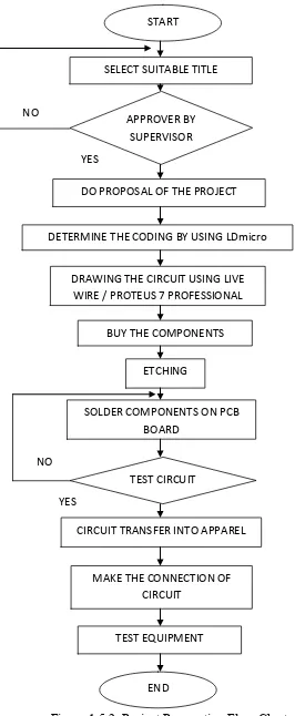
7 1.5.2 Project Preparation Flow Chart
Figure 1.5.2: Project Preparation Flow Chart START
SELECT SUITABLE TITLE PROJECT
APPROVER BY SUPERVISOR
DO PROPOSAL OF THE PROJECT
DETERMINE THE CODING BY USING LDmicro
BUY THE COMPONENTS DRAWING THE CIRCUIT USING LIVE
WIRE / PROTEUS 7 PROFESSIONAL
8
8
The preparation flow chart is summarized about the flow of the progressing project. Firstly, the information about the Secure Water Filter system is searching and collected to analyse the problem statements which are facing the current product before do the confirmation to select the title of the project. After received the approved form the supervisor, the proposal of the project must be prepared to determine the problem and development to implement the project clearly. After the analysis has done, the hardware component and software has been selected. Then, the related circuit that can assemble in well and the construction of the coding by using the specific software can be finished. Furthermore, the hardware and software are built must be tested. Find the source of error and finally is to solve problem.
1.6 Report Structure
This report will cover five chapters. The first chapter will be the background, introduction, problem statement, objective and scope of work. Literature review is discussed in Chapter II while for Chapter III, the project methodology is discussed. Chapter IV will cover on hardware and software implementation and last but not least the conclusions and suggestions are respectively covered in Chapter V. To obtain a successful project, there are several chapters that need to view and study nicely. The following are the main chapters and it is short descriptions.
Chapter I : Study the objective and scope of work on the project. Chapter II : Literature review about Secure Water Filter.
Chapter III : Project methodology includes the planning, the development of the design and the management of the project.
Chapter IV : Hardware and Software implementation. Chapter V : conclusions and suggestion on the project.