UNIVERSITI TEKNIKAL MALAYSIA MELAKA
INTELLIGENT KEYCHAIN
This report submitted in accordance with requirement of the Universiti Teknikal Malaysia Melaka (UTeM) for the Bachelor’s Degree in Electronics Engineering
Technology (Industrial Electronics) (Hons.)
by
AZRUL BIN ABDILLAH
B071110225
900205-12-5645
UNIVERSITI TEKNIKAL MALAYSIA MELAKA
BORANG PENGESAHAN STATUS LAPORAN PROJEK SARJANA MUDA
TAJUK: INTELLIGENT KEYCHAIN
SESI PENGAJIAN: 2014/15 Semester 2
Saya AZRUL BIN ABDILLAH
mengaku membenarkan Laporan PSM ini disimpan di Perpustakaan Universiti Teknikal Malaysia Melaka (UTeM) dengan syarat-syarat kegunaan seperti berikut:
1. Laporan PSM adalah hak milik Universiti Teknikal Malaysia Melaka dan penulis. 2. Perpustakaan Universiti Teknikal Malaysia Melaka dibenarkan membuat salinan
untuk tujuan pengajian sahaja dengan izin penulis.
3. Perpustakaan dibenarkan membuat salinan laporan PSM ini sebagai bahan pertukaran antara institusi pengajian tinggi.
4. **Sila tandakan ( )
SULIT
TERHAD
TIDAK TERHAD
(Mengandungi maklumat yang berdarjah keselamatan atau kepentingan Malaysia sebagaimana yang termaktub dalam AKTA RAHSIA RASMI 1972)
(Mengandungi maklumat TERHAD yang telah ditentukan oleh organisasi/badan di mana penyelidikan dijalankan)
Alamat Tetap:
Tarikh: ________________________
Disahkan oleh:
Cop Rasmi:
Tarikh: _______________________
DECLARATION
I hereby, declared this report entitled “Intelligent Keychain” is the results of my own research except as cited in references.
Signature : ……….
Author’s Name : ………
APPROVAL
This report is submitted to the Faculty of Engineering Technology of UTeM as a partial fulfillment of the requirements for the degree of Bachelor of Engineering Technology (Industrial Electronic) (Hons.). The member of the supervisory is as follow:
i
ABSTRAK
ii
ABSTRACT
iii
ACKNOWLEDGEMENT
In completing this project, I have received some assistance from my supervisor, other lecturers, family and also my friends. First of all, I would like to show my upmost gratitude to my supervisor Mr Tg Mohd Faisal Bin Tengku Wook for giving the guidance and support by sharing his expertise and knowledge with me. He provided advice for me to explore some new idea in my project and solution for difficult problem. I am very thankful for his advices and guidance until the successfulness of the project.
In addition, I would like to give my recognition and thanks to my previous panels, Engr. Mohd Syahrin Amri Bin Mohd Noh and Mr Hasrul Nisham Bin Rosly for their patience in correcting my proposal so that I was on the right track in completing this project. I was able to understand more about the method to apply fundamental knowledge into this project with their advices.
Moreover, I owe a debt of thanks to all those time, concern and supports were given by my parents and friends during the process of completing this report. I am thankful to everyone who always inspires me directly and indirectly during the milestone of completing my final year project.
iv
2.3.4 Automatic Software Reset 17
v 3.1.2 Intelligent Keychain Flowchart (Implementing) 28
3.1.3 Overall Project Flowchart 29
3.2 Conclusion 30
CHAPTER 4: Result and Discussion 31
4.1 Expected Result 31
4.2 Schematic Design of the Circuit 32
4.5.1 Altium Software Designer 41
4.5.2 Arduino Suite Software 44
4.6 Result 45
4.7 Discussion 46
4.8 Component Chart 49
CHAPTER 5: Conclusion and Future Work 50
5.1 Conclusion 50
5.2 Limitation 52
vi
REFERENCES 54
APPENDICES 55
A GANT CHART PSM I 56
B GANT CHART PSM II 57
C CODING 58
D GSM SIM900 DATA SHEET 62
vii Comparison between Arduino and PIC Comparison between Java and C++
7
4.1 Differences between GSM 47
viii
LIST OF FIGURES
1.1 Communication Technologies 1
2.1 Evolution of G 7
3.1 Flowchart for Guideline of the PSM 23
3.2 Flowchart Of FYP I Activities Sequences 24
3.3 Flowchart Of FYP II Activities Sequences 26
3.4 Flowchart PSM I and PSMII
Full Schematic for Intelligent keychain Back Layer for PCB Board
Closed View Back Layer for PCB Board Closed View Back Layer for PCB Board Positive Layout for PCB Board
Negative Layout for PCB Board
The Windows Devices Manager Showing Serial Port The Arduino IDE of Serial Port
The Arduino Interface Upload and Verified The GSM and Arduino Nano Coding Printed Circuit Board (Front View). Printed Circuit Board (Back View) Altium Icon installed in PC
ix 4.16
4.17
Actual Size for the Intelligent Keychain Prototype 9V battery
x
LIST OF ABBREVIATIONS, SYMBOLS AND
NOMENCLATURE
GSM - Global System for Mobile
G - Generation
GPRS - General Packet Radio Service
4G - Fourth Generation
GND - Ground
UART - Universal Asynchronous Receiver/Transmitter
1
1.1 Background
This project is about providing a prototype of system alert for a people which is attach to this keychain (for example car key).This project is combining Arduino and GSM technology. The function of GSM is to receive the information send from phone example call or SMS. Through this action, the Keychain will be ringing or buzz because the keychain is attach with the small buzzer and speaker act as indicator. It contact immediately to inform the location of the keychain in real time. The system covered one type of sensor as the basic of security system for home. The sensor is vibration sensor. The operation of this security system is illustrated in Figure 1.1.
Figure 1.1 Communication Technologies
INTRODUCTION
2 The new age of technology has redefined communication. Most people nowadays have access to mobile phones and thus the world indeed has become a global village. At any given moment, any particular individual can be contacted with the mobile phone. But the application of mobile phone cannot just be restricted to sending SMS or starting conversations. New innovations and ideas can be generated from it that can further enhance
Technologies such as Infra-red, Bluetooth, which has developed in recent years goes to show the very fact that improvements are in fact possible and these improvements have eased our life and the way we live.
Remote management of several home and office appliances is a subject of growing interest and in recent years we have seen many systems providing such controls. These days, apart from supporting voice calls a mobile phone can be used to send text messages Sending written text messages is very popular among mobile phone users. Instant messaging, as it is also known, allows quick transmission of short messages that allow an individual to share ideas, opinions and other relevant information. This project used the very concept to design a system that acts a platform to receive messages which in fact are commands sent to control different appliances and devices connected to the platform.
3
1.2 Problem Statement
(a) The motivation on developing this project is to decrease lose belonging in our society. This project could be attached with anything as long as our belonging. (b) Frequency drop or loss of goods in the community.
(c) Take a long time to find the lost.
1.3 Project Objective
(a) To study about GSM and Arduino board.
(b) To develop prototype GSM Intelligent Keychain using Arduino. (c) To help people to relocated the item that they people misplace.
1.4 Project Scopes
The scope of this project is limited and thus, the study is narrowed down to several points. This is to ensure the project is heading to the right direction in order to achieve its objectives. The scopes and guidelines of this project are listed below:
(a) To learn and understand the basic GSM (Global System for Mobile Communications.
(b) To study on the Arduino board.
4
1.5 Report Structure
This report is divided into 5 chapters. Chapter one which is about the introduction has briefly introduced the overall system of the project with title’s Intelligent Keychain. This introduction part consists of project background, objectives, scope of project, problem statement, signification of project and report structure.
Chapter 2 presents the literature review which discusses the detailed research on the overall structure of GSM Intelligent Keychain technology. It includes the study of GSM Module (transmitter and receiver), Arduino Uno Board, Buzzer and other theory related with this project and additional component.
Chapter 3 explains about the project methodology. Project methodology gives details about the whole method being used to solve the problems in order to complete this project. This chapter contains the methods used for collecting data, processing and analyzing of data.
Chapter 4 is discusses about the result and discussion of the whole project. It covers the finding and analysis throughout the research and the project development. Besides, this chapter also discusses about the simulation and practical measured results of the circuit used in this project.
5 This chapter discusses the research on the overall structure of Intelligent Key Chain which is included the review of GPS GSM module, Arduino Uno, buzzer indicator, programming language and other theory related with this project .
2.1 Reviews on GSM (Global System for Mobile Communication)
GSM (Global System for Mobile Communications, originally Groupe Spécial Mobile), is a standard developed by the European Telecommunications Standards Institute (ETSI) to describe protocols for second generation (2G) digital cellular networks used by mobile phones. The GSM standard was developed as a replacement for first generation (1G) analog cellular networks, and originally described a digital, circuit-switched network optimized for full duplex voice telephony. For this project, SIM 900 GSM module will be use (Martin, 2013).
First generation refers to the analog “brick phones” and “bag phones” as they were first introduced for mobile cellular technology. Cell phones began with 1G and signify first generation wireless analog technology standards that originated in the 1980s. 1G was replaced by 2G wireless digital standard.
Next is for 2G evolution. 2G signifies second generation wireless digital technology. Fully digital 2G networks have replaced analog 1G, which originated in the 1980s. 2G networks first commercially began on the Global System for Mobil
6 Communications, or GSM, standard which is first used in commercial practice in 1991 by Radiolinja, a Finnish GSM operator that was founded on September 19, 1988. Radiolinja is now part of Elisa, which was known in the 1990s as the Helsinki Telephone Company.
Between 2G and 3G, 2.5G technology was released. While 2G and 3G have been officially defined as wireless standards by the International Telecommunication Union (ITU), 2.5G has not been defined and was created only for the purposes of marketing. 2.5G has seen some of the advances inherent in 3G networks (including packet-switched systems). Several technologies that have been considered as the evolutionary step to 3G include Enhanced Data rates for GSM Evolution (EDGE) and Code Division Multiple Access (CDMA) 2000 1X (Temple, 2013).
The 3rd generation of mobile networks has become popular largely thanks to the ability of users to access the Internet over devices like mobiles and tablets. The speed of data transmission on a 3G network ranges between 384KBPS to 2MBPS. This means a 3G network actually allows for more data transmission and therefore the network enables voice and video calling, file transmission, internet surfing, online TV, view high definition videos, play games and much more. 3G is the best option for users who need to always stay connected to Internet (Bureau of Telecommunications Regulation, 2012).
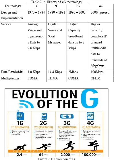
4G is the term used to refer to the fourth generation of mobile wireless services that has been defined by the ITU and its Radio Communication Sector (ITU-R) and established as an agreed upon and globally accepted definition in International Mobile Telecommunications Advance (IMT-Advanced).
7 Table 2.1: History of 4G technology
8
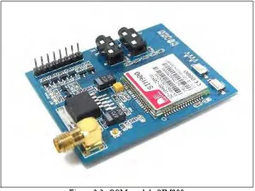
2.2 GSM (Global Review of GSM Module)
Figure 2.2: GSM module SIM900
9
2.2.1 Power ON GPRS module
User can power on the GPRS module by pulling down the PWR button or the P pin of control interface for at least 1 second and release. This pin is already pulled up to 3V in the module internal, so external pull up is not necessary. When power on procedure is completed, GPRS module will send following URC to indicate that the module is ready to operate at fixed baud rate.Power On/Off and GSM on SwitchText
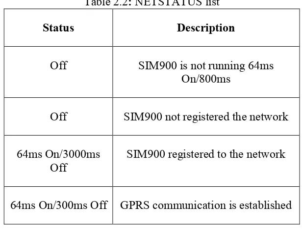
2.2.2 Indicator LED and Buttons.
NETSTATUS: The status of the NETSTATUS LED is listed in following table:
Table 2.2: NETSTATUS list
Status Description
Off SIM900 is not running 64ms On/800ms
Off SIM900 not registered the network
64ms On/3000ms Off
SIM900 registered to the network
64ms On/300ms Off GPRS communication is established
STATUS: Power status of SIM900.
PWR: Power status of GPRS module.
PWR: Press the POWER button for a moment to power on the SIM900 module.
10
2.2.3 Overview
GPRS module is a breakout board and minimum system of SIM900 Quad-band/SIM900A Dual-band GSM/GPRS module. It can communicate with controllers via AT commands (GSM 07.07, 07.05 and SIMCOM enhanced AT Commands). This module supports software power on and reset.
2.2.4 Features
(a) Quad-Band 850/ 900/ 1800/ 1900 MHz. (b) Dual-Band 900/ 1900 MHz.
(c) GPRS multi-slot class 10/8GPRS mobile station class B. (d) Compliant to GSM phase 2/2+Class 4 (2 W @850/ 900 MHz). (e) Class 1 (1 W @ 1800/1900MHz).
(f) Control via AT commands (GSM 07.07, 07.05 and SIMCOM enhanced AT Commands).
2.2.5 Specification.
Table 2.3: Specification of GSM SIM900
PCB size 71.4mm X 66.0mm X1.6mm
Indicators PWR, status LED, net LED
Power supply 5V
Communication Protocol UART