DOI: 10.12928/TELKOMNIKA.v13i3.1978 1097
Computational Simulation of Comb-plate Expansion
Joints
Liang Tang*1, Xiaoyan Zhang2, Jian Tang3, Wu Jie4
State Key Laboratory Breeding Base of Mountain Bridge and Tunnel Engineering, Chongqing Jiaotong University, Chongqing 400074, China, Ph.: +86-2362652316 *Corresponding author, e-mail: cqutang@163.com1, cquzhang@126.com2, wsnarab@gmil.com3,
jiezi19891003@126.com4
Abstract
A finite element model of the expansion Joints’ common damages of a novel comb-plate by using the finite element software ABAQUS is presented in this paper. The mechanical behavior of expansion Joints is analyzed to verify the weak parts of it. The research results provide a reference for the design of the comb-plate expansion Joints.
Keywords: comb-plate expansion joints, stress distribution, numerical simulation
Copyright © 2015 Universitas Ahmad Dahlan. All rights reserved.
1. Introduction
Bridge expansion joints is a gap which preset between the upper parts of the main beam of bridge to adapt the material swell-shrinking deformation of bridge structure. The telescopic device is made of rubber, steel and other components, which is setting at bridge expansion joints and to make the vehicle move smoothly through the deck, to meet the needs of the deformation on the upper structure of the bridge and the general term for all sorts of devices.
In general, bridges' expansion joints have two functions. Firstly, vertical and horizontal loads given by vehicle and others can be properly transferred to beams through supporting elements. Secondly, they can adapt to changes in the bridge longitudinal and transverse displacements, and they also should be able to adapt to the settlement of bridge pier and the changes of rotation angle caused by warping at the end of the beam [1].
Although the expansion facility is accessories of bridge, it is vital for durability and driving safety. As traffic increases rapidly, speed and load of vehicle Increase incessantly, the damage of bridge expansion joint is prominent [2]. Once the expansion joint is damaged, the effect or consequence is very serious.
The developed countries in Europe and America have been in ahead of the bridge expansion joints industry. After many years of development, these countries has developed their own mature product. We are familiar with the bridge expansion joints made by many companies like MAURER in German, D.S.BROWN and Watson Bowman in the United States, Mageba in Switzerland, BRITFLEX in United Kingdom.
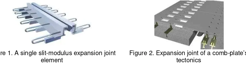
Figure 1. A single slit-modulus expansion joint element
Figure 2. Expansion joint of a comb-plate’s tectonics
comb-plate telescopic device as shown in Figure 2. The former is mostly used in large or grand bridges which with larger amount of stretching [3]. The latter is usually used in small or medium bridges which with medium amount of stretching [4].
The design of a comb-plate expansion joint can be carried out by a simple static analysis as a beam. The thickness of the plate is determined by the moment. The anchor bolts are designed according to the reaction force. To take into account any dynamic amplification, the moment and the reaction force are increased by a dynamic amplification factor (DAF) which is typically 1.
amplification factor,
M
cis the moment of the comb-plate expansion joint ait the end of the bridge deck. tis the thickness of the plate, I is the second moment of inertia of the plate,f
y is theyield strength,
R
A is the reaction of the anchor bolts, and n is the number of the anchor bolts within the width of the module under design.Typically, comb-plate expansion joints are designed by the concept of working stress design. Let us consider a typical design example. The length l is 0.24m, the thickness t is 45mm, the load factor
is 2.5, the impact factor i is 1, and the strength reduction factor
is0.5. Then, the safety factor becomes
1
i
8
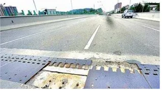
which is very large. With such a large safety factor, it is hard to expect failure of comb-plate expansion joints in the service condition. However, the failure of comb-plate expansion joints can often be observed. Most of the failure is due to the failure of the anchor bolts rather than of the plate itself. Once the anchor bolts fail, the plate pops up as shown in Figure 3.Figure 3. Failure of the comb-plate expansion joint in Tang-Min Bridge, China in which the right plate popped up because of the failure of the anchor bolts
Such an unexpected failure of the anchor bolts leads to many unjustified hypotheses to explain the mechanism. Some of them include that the failure of the anchor bolts would happen because of the direct impact of running tire to the end of the plate when the plate tilts excessively as shown in Figure 3 due to the thermal gradient of the deck or long-term creep deflection. But according to the authors’ calculation, the movement of the plate end due to the rotation of the deck is at most 5 mm for a typical 50 m span concrete box girder bridge, which is not enough to cause the failure of the anchor bolts by the wheel load at the end of the plate. This means that there must be another failure mechanism, rather than the load case considered in the typical design procedure.
anchor bolt damage and the concrete damage which under tooth plate. And among these, the most serious and common phenomenon is that the concrete damage resulted in the destruction.
As a fundamental part of the bridge structure, telescopic device has become one of problems in the bridge construction and maintenance. Since the telescopic device exposure to the atmosphere long-term, under long-term repeated loading and the environment is bad, it is more difficult to repair and most easily destroyed as a bridge element. If bridge expansion has a slight defect or deficiency in design or the construction, which would cause early damage; the destruction of the bridge expansion joints may cause a lot of vehicle impact load. So driving conditions worsen dramatically and reduce the life of the telescopic device.
Damage to the expansion joint has several major reasons which include the design, construction, maintenance, product performance, and so on. For the design, wanting to take measures to avoid the congenital defects in design stage, we must make mechanical performance of expansion joint clear.
2. Calculation Model
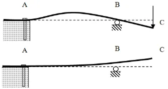
As mentioned in the previous section, the reaction itself caused by the tilt of the plate end is not significant enough to cause the failure of the anchor bolts. But the unevenness caused by the tilt makes the plate easy to vibrate. The vehicle load causes the maximum reaction of the anchor bolts when it is placed at the end of the comb-plate expansion joint. The plate would deform as in Figure 4 because the plate is supported at point A by the anchor and point B by the deck. Note that point B supports against downward displacement, not upward displacement. Therefore, the plate must pop up as shown in Fig.4 by the conversion of deformation.
Figure 4. Two possible deformation of a comb-plate expansion joint due to the load acting at the end of the plate and the spring-back behavior after the load passes over the joint
Figure 5. Anchor bolts and embedded steel skeletons
Figure 6. Location of anchor bolts in the concrete
element, all of them must be divided as possible as small when make unit division. Due to using plastic damage constitutive relations, eight-node element is selected to avoid non-convergence in calculating for the concrete in anchorage area. Model includes 370,000 nodes and 330,000 units, and the Figure 5 is a schematic diagram of model and mesh. We fetch unit width comb-plate (with the width of 1m) in transverse to make modeling analysis under considering the vertical static loads and horizontal calm force. According to the stress situation of the comb-plate in actual operation, we load them on comb-plate in the most unfavorable position once, which is in the mid-span of the joints shown in Figure 8.
Figure 7. Sketch of grid model Figure 8. Diagram of loading on a model
3. Analysis
Based on comb-plate expansion joints for the ultimate loading condition, analysis and calculation of the above model,results are given as follows. Tensile stress is positive and pressure is negative in these results.
3.1 The Stress and Deformation of Comb-plate
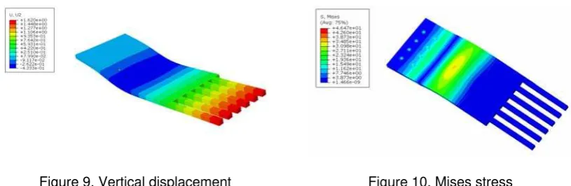
Vertical displacement nephogram and Mises stress nephogram of comb-plate are shown in Figure 9 and Figure 10. The maximum positive displacement (vertical up) of the comb-plate appears in the end of teeth, and the amount of which is only 1.62mm (straight up). The maximum negative displacement (vertical down) appears in the joints of the cross, which is only - 0.43mm. The maximum Mises stress of comb-plate is 46.5Mpa in the mid-span of expansion joints through Figure 10, it is far less than the yield stress of steel.
Figure 9. Vertical displacement Figure 10. Mises stress
3.2. Stress of Embedded Skeleton in Fixing Bolts and Concrete
Figure 11. Mises stress of anchoring zone of concrete
Figure 12. Maximum principal stress in anchorage
3.3 Stresses of Concrete in Anchorage Zone and Equivalent Plastic Deformation
Concrete’s distribution of principal stress in anchorage zone as shown in Figure 12. A large principal stress of concrete appear to the local anchorage zone from the chart. Especially the maximum principal stress of concrete which near anchor bolts can reach 1.98Mpa, and such a large stress value is distributed in the whole buried depth of the concrete. Viewing the equivalent plastic deformation of concrete (PEEQ) as shown in Figure 13, in order to clarify the destruction of concrete further. Around the first row of bolts, concrete appears equivalent plastic deformation within the range of 12cm2 and depth of 2cm; around the first row of bolts, concrete appears equivalent plastic deformation within the range of 24cm2 and depth of 10cm. Thus, the concrete in anchorage zone is the weakest part of the comb-plate telescopic device. The concrete has damages in some degree when it works on normal loads.
Figure 13. Equivalent plastic deformation (PEEQ) of concrete in anchorage zone
3.4. Considering the Stress Condition of Expansion Joint Under Different Parameters Modifying each of the key geometry parameters in the model, such as: keeping the same bolt area, change the number of anchoring bolts; keeping the same spacing between two rows of bolts, change the distance from a row of bolts between expansion joints; change the comb-plate thickness. The comparative analysis of summarized impact of structural parameters on the size of the force behavior and deformation behavior of the comb-plate telescopic device.
When retaining total area unchanged, only change the number of anchor bolts, the results of the comparative analysis show that the regional scope of the maximum principal stress in concrete remained unchanged, and plastic damage occurs basically in the same regional scope. But the maximum Mises stress should have changed greatly in the anchoring bolts, as shown in Table 1. Obviously, with the number of anchor bolts increasing, stress of each and the space decrease, all of that should increase the difficulty of pouring concrete in anchorage zone.
Table 1. Influence of bolt’s number on the force
Number of bolt 6 8 10
Keeping the space between the two rows of bolt, the space between anchor bolts and the edge of expansion joints increase from 100mm to 250mm, the Mises stress in the first row of bolts reduced from 126Mpa to 89.6Mpa, Mises stress in the second row of bolts from 71.3Mpa to 87.5Mpa, Mises stress of the two rows in bolts tend to be equal. So changing the distance of the expansion joints between one row of bolts, we find that the farther from the expansion joints, the more homogeneous of the stress distribution between the two rows of bolt is, as showing in Table 2. But the maximum principal stress and the plastic damage of the concrete what is changed little in the anchorage zone.
Table 2. The influence of spacing bolts to the edge of the expansion joint on force Spacing between bolts and the edge of The expansion joint (mm) 100 150 200 250 Mises stress of the first row’s bolts (MPa) 126 110.7 98.8 89.6 Mises stress of the second row’s bolts (MPa) 71.3 78.2 83.4 87.5
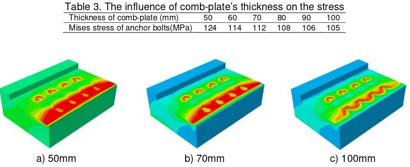
While keeping the other parameters constant, when the thickness of the comb plate is 50mm, the corresponding stress is 128Mpa, and when the thickness is 60mm, the corresponding stress 114Mpa, anchor bolt stresses reduced significantly; but when the thickness exceeds 60mm reach 100mm, the anchor bolt stresses only reduced from 114Mpa to 105MPa, the trend is clearly slowed. so changing only the thickness of the comb-plate, we find that with increasing thickness of the comb-plate, the maximum principal stress range of concrete anchorage zone decreased, as shown in Figure 14. At the same time as shown in Table 3, the Mises stress in anchor bolts also decrease. And with the increase of comb-plate’s thickness, the lower flexibility and the degree of upwarp at the end of tooth will reduce correspondingly, which will improve the driving experience.
Table 3. The influence of comb-plate’s thickness on the stress Thickness of comb-plate (mm) 50 60 70 80 90 100 Mises stress of anchor bolts(MPa) 124 114 112 108 106 105
a) 50mm b) 70mm c) 100mm
Figure 14. The distribution of concrete’s maximum principal stress under different thickness of comb-plate in the anchorage zone
Figure. 15 Flexible bolt and flexible gap between steel plate and channel assembly [8]
4. Conclusion
After analyzing a certain type of comb-plate expansion joint finite element modeling, it is concluded as follows:
(1) For the comb-plate expansion joint,the ultimate stress of anchor bolts and concrete in anchorage zone agree well with the phenomenon that anchor bolts and concrete in anchorage zone are the most likely to damage in practice.
(2) Due to the force of concrete around anchor bolts is complex and more prone to plastic damage, workers should try to ensure the quality of construction.
(3) The number of anchor bolts increased can reduce the stress of bolts and concrete. If the anchor bolts farther away from the joints, the stress distribution is more uniform. The increase of comb-plate’s thickness can improve the stress distribution of bolts and concrete in anchorage zone, and reduce the deformation of comb-plate.
(4) Due to the anchor bolts fully anchored in the concrete, unable to meet the displacement under load, which likely to cause bolts loosening and set aside for comb plate of steel telescopic device. The comb plate will fall off as a result. In recent years, a steel comb-shaped bridge expansion a multi-bit performance to change a large amount of stretching, has been widely used in large-span suspension bridges, cable-stayed bridges, etc. The domestic bridge engineering have done a lot of useful exploration. The basic approach is that provided mobile relative rotation connection mechanism in the front end or the root of a steel comb plate to achieve vertical lateral and torsional displacement space and other multi-directional displacement. The usual practice is setting confined rotating shaft and the rotation of spherical bearing at the root’s downside of the active block steel comb plate, and then, through grouping unit points block comb plate and confined rotating shaft (or the rotation of spherical bearing) effective to make steel movable comb plate could adapt to the long-span bridge vertical, lateral, torsional space deformation, thus achieve security and durable of bridge telescopic device.
influenced the quality of the welding and concrete pouring, which lead cabinet slump and some other damages. If these deficiencies have not been addressed and resolved, it will affect traffic safety and steel comb-type telescopic device’s working life seriously.
Therefore, in the steel comb plate telescopic device to multi-directional displacement seam develop its improvements are in the right direction, in the application of concrete bridges, should be further need to improve the design displacement device according to the accepted.
Acknowledgements
The authors would like to acknowledge the supported of the National Natural Science Foundation of China (Grant No. 11302271), the Application Development Key Program of Chongqing (Grant No. cstc2013yykfB0123) and Chongqing Jiaotong University Bridge and Tunnel Mountain State Key Laboratory Breeding Base Open Fund Project.
References
[1] KA Ravshanovich, H Yamaguchi, Y Matsumoto, N Tomida, S Uno. Mechanism of noise generation from a modular expansion joint under vehicle passage. Engineering Structures. 2007; 29(9): 2206-2218.
[2] B Zuada Coelho, AHJM Vervuurt, WHA Peelen, JS Leendertz. Dynamics of modular expansion joints: The Martinus Nijhoff Bridge. Engineering Structures. 2013, 48(3): 144-154.
[3] Ramesh B Malla, Brian J Swanson, Montgomery T Shaw. Laboratory evaluation of a silicone foam sealant bonded to various header materials used in bridge expansion joints. Construction and Building Materials. 2011; 25(11): 4132-4143.
[4] YZ Zhu, HF Wang, ZF Sang. The effect of environmental medium on fatigue life for u-shaped bellows expansion joints. International Journal of Fatigue. 2006; 28(1): 28-32.
[5] Jhabindra P Ghimire, Yasunao Matsumoto, Hiroki Yamaguchi, Itsumi Kurahashi. Numerical investigation of noise generation and radiation from an existing modular expansion joint between prestressed concrete bridges. Journal of Sound and Vibration. 2009; 328(27): 129-147.
[6] Liantong Mo, Donglin Shu, Xun Li, M Huurman, Shaopeng Wu. Experimental investigation of bituminous plug expansion joint materials containing high content of crumb rubber powder and granules. Materials & Design. 2012; 37(5): 137-143.
[7] Goangseup Zi, Xingji Zhu. Asymmetric vibration of finger-type bridge expansion joint for design consideration. Engineering Structures. 2014; 70(3): 53-62.

![Figure. 15 Flexible bolt and flexible gap between steel plate and channel assembly [8]](https://thumb-ap.123doks.com/thumbv2/123dok/240878.502864/7.595.224.373.85.182/figure-flexible-bolt-flexible-steel-plate-channel-assembly.webp)
