DOI: 10.12928/TELKOMNIKA.v12i2.1833 405
Low Mutual Coupling Dualband MIMOMicrostrip
Antenna Parasiticwith Air Gap
Yuli Kurnia Ningsih, Rastanto Hadinegoro
Department of Electrical Engineering, Faculty of Industrial Technology, Trisakti University Jl. Kyai Tapa No.1 Grogol, Jakarta 11440, Indonesia,ph/fax:6221-5663232ext8403/5605841
*Corresponding author, e-mail : [email protected]; [email protected]
Abstract
Multiple Input Multiple Output (MIMO) systems use multiple antennas at both the transmitter and receiver to improve quality and data rate mobile communication.In recent year, various antennas working on dual or multi bands have been developed. The increasing mutual coupling is one of the negative effect due to the addition of antenna element in MIMO system.This paper present a low mutual coupling dualband MIMO 2x2 antenna. The proposed MIMO antenna is able to work in dual frequency at 1.8GHz and 2.35GHz.To obtain the optimum design, the charactertistic of proposed antenna are numerically investigated through the phisical parameters of antenna.By parasitic layer with air gap, mutual coupling can be decreased until 50 % and gain of the proposed antennacan be improved until 50%. The obtained results show that proposed antenna has a compact size and a bandwidth of 100 MHz.which is suitable for LTE application.
Keywords: MIMO, mutual coupling, microstrip dualband antenna
1. Introduction
The demand for higher quality and data rate was growing fast in the past few years. One of the most promising solutions to this problem is Multiple Input Multiple Output (MIMO) system [1]. The MIMO technology made a great breakthrough by satisfying the demand of higher quality mobile communication services without using any additional radio resources [1],[2] and it has a significant ability to increase data throughput without additional bandwidth or transmit power (transmitter power). One type of antenna that can be used to increase the channel capacity of MIMO is a microstrip antenna [3]. Various microstrip antenna working on multiband frequency have been developed and reported. In [4]-[6], dual band or tri band antennas have been achieved, but gain of the antennas is not explained. An effective way to obtain dual-band resonant frequency is to use a fractal monopole with a U-shaped slot just like in [7] but the gain remains above 2.0dBi.
Unfortunately, in MIMO system with multiband, mutual couplingis signifcant issues need to be overcome to enhance theeffectiveness of MIMOand it becomes more critical when inter-element spacing is very small. Achieving high isolationbetween the radiating elements is a challenging task and also it is difficult to control the isolation over the desired bands. This kind of situation can occur in mobilecommunications, especially in mobile phones, where space limitationsbecome an important variable.Mutual coupling is a function of antenna spacing, number of antennas, and direction of each ray relative to the arrayplane. Hence, it becomes difficult to match the antenna impedance,which is important for efficient energy transfer [2].
2. Numerical design of Antenna
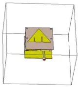
The geometry of MIMO (2x2) is based on single patch antenna using two slots with different height for dual frequency operation, co-planar waveguide feed line. Figure 1 illustrates a shape of the single patch dual-band antenna.
Figure 1. Shape of single patch dualband antenna
2.1. Slots of antenna
Basically, the proposed dual-band antenna is modified with add two slots at a single band antenna. Here, the antenna with the frequency resonator is a 1.8 GHz is determined to obtain dual-band antenna. The slot is the most-widely used method to achive more than one frequency which still maintains the compactness of the antenna [8]-[11]. The proposed antenna deployed on an FR-4 Epoxy substrate with permitivity of 4.3, thickness of 1.6mmand loss tangent (tan δ) = 0.0265.As both the radiating elements and the CPW feeding mechanism are implemented on the same plane; hence, fabrication of the proposed antenna is very easy using a single-sided metallizationprocess.
2.2. Co-planar wave guide (CPW) fed
A CPW fed makes the antenna more suitable for compact wireless communication because of its features like uniplanar structure, easily manufactured and easily integrated with other microwave integrated circuits.Another important advantage of CPW-fed is wider bandwidth than CPS and microstrip line. The 50ΩCPW transmission is used to excitite the antenna. For the given values off substrate parameters, the CPW dimensions of the CPW line are investigated.
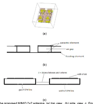
2.3. Parasitic layer with air gap
Several approaches to improving the radiation efficincy and obtaining a high-gain antenna. The electric lens antenna was adpted to achieve a high-gain antenna[12]. However,the commonly used lens antenna is constructed using an expensive crystal material and it is difficult to mount it on the MMIC packet. The technique for improving the radiation efficiency and obtaining a high-gain by arranging parasitic elements above the feeding microstrip antenna elements is examined [13]-[16]. In this paper, to achieve a high-gain, the next step in numerical design of MIMO antenna is employing two parasitic layers. Four patchs dual-band element without ground on the first parasitic layer and four patchs dual band element with CPW fed on the second parasitic layer.
3. Design of MIMO 2x2 Dual Frequency Antenna
The design is started from the single band-notched characteristic at 1.8GHz and at 2.35 GHz respectively. However, with combination slot pair from the single element antenna, a dual band-notched characteristics antenna is achieved. The slots are carefully tuned so that the antenna can be operable at low and high frequency bands. The dual-band notched characteristic radiator is connected to a50Ω coplanar wave guide (CPW) feed-line.
r
is a triangular patch only and the second layer consists of triangular patch with CPW fed and a layer of air gap between the two layers of substrate.
The geometry of the MIMO 2x2 dual frequency antenna with CPW is shown in Figure 2.The geometry and configuration of antenna for single-band can be expressed following [1].The patch antenna is calculated by (1), (2), (3) and (4) for design a microstrip antenna shaped triangular.
(1)
For mode TM10 frequency resonance by the following equation:
(2)
Where ae is:
(3)
And a issubstituted:
(4)
For MIMO (2x2) antenna in Figure 2, dis distance betweenantenna elements and given by [4] :
݀ ൌఒସ (5)
4. Simulation Result
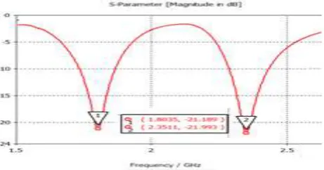
Simulation tools have been used to calculate S parameters, based on the Method of Moments. The final optimization, the reflection loss factor vs frequency is depicted in Figure 3. The reflection coefficient is achieved below -21.19 dB at 1.8 GHz and -21.99dB at 2.35 GHz. The antenna can produce dual band with notch characteristics.
Figure 3.Simulation result of the dual bandMIMO 2x2 Antenna parasitic with air gap
When the number of antenna elements is placed in forming the arrays, mutual coupling between the antenna elements is a critical issue. Mutual coupling is a potential source of performance degradation in the form of deviation of the radiation pattern from the desired one, gain reduction due to excitation of surface wave, increased side lobe levels etc.
Effect of mutual Coupling also occurs in MIMOantenna. One reason is the wave surface. It can change the amount of current, phase, and the distribution of each element so that the over all antenna radiation pattern is different than not having coupling. When the distance between the adjacent elements are not appropriate with equation (2), mutual coupling effects will increase [6].
The mutual coupling simulation at distances of 8 cm is shown in Figure4. S21 is almost
-40 dB at 1.8GHz and >-40 dB at 2.35GHz, which shows good isolation between antenna elements andit can be seen that thesimulation are in a good agreement.
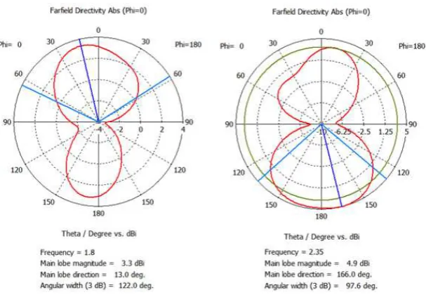
Figure 5 shows the radiation pattern of the dual-band-MIMO 2x2 antenna with CPW fed in plane. Half-power beam width is 122.0at frequency of 1.8GHz, and 97.6 at frequency 2.35GHz. The main lobe has its peak power at 13 and at 2.35GHz, the main lobe has its peak power at 166.
Figure 5. Simulated Radiation Pattern of the dual-band-MIMO 2x2 antenna parasiticwith air gap at 1.8 GHz and 2.35 GHz
Figure 6.3-D Visual of Radiation Pattern of the dual-band-MIMO 2x2 antenna parasiticwith air gapat 1.8 GHz and 2.35 GHz
Figure 6 is a3-D radiation pattern at a frequency of 1.8GHz and 2.35GHz. It can be seen that the antenna radiation pattern is directional which leads only in one direction and direction looks great in the redarea. Directivity antenna at a frequency of 1.8GHz is 3.6dBi while the 2.35GHz frequencyis equal to 5.3dBi.
The impact of parasitic with air gap is clearly noticeable from Table 2. The improvement of 89% averagely at the desired frequency is due to the fact that the structure of parasitic with air gap providing good isolation characteristics compared to the structure of paracitic without air gap.
Table 2 . The effect of parasitic with air gap on mutual coupling and gain
5. Conclusion
A novel configuration of dual-band MIMO 2x2 microstrp antenna withstructure of paracitic with air gap has been studied and simulated. The results of this simulation antenna microstrip for frequency of 1.8GHz shows return loss is -21.19dB with impedance bandwidth about 125MHz and at 2.35GHz shows return loss is -21.99dB with impedance bandwidth about 110MHz. Structure of paracitic with air gap can enhanched the mutual coupling significantly. The result of simulated HPBW is 122oat1.8 GHz and 97.6° at 2.35 GHz, respectively.It is seen that the gain remains above 3.5dBiin the dual LTE bands.Therefore the proposed antenna is applicable as new candidate for dual frequency antenna to make MIMO in (2x2) antenna microstrip for LTE application in Indonesia.
Acknowledgment
This work is supported by the Program of Research Grant Indonesia Goverment, Kopertis Wilayah III Direktorat Jenderal Pendidikan Tinggi Kementerian Pendidikan dan Kebudayaan (Contract No. 002/K3/KM/SPK/2013)
References
[1] Hua L, Jing B, Shujian L, Juanping W. Simulation models for MIMO wireless channels. Telkomnika Journal. 2014; 11(1):158-166.
[2] Astely D, and et al. LTE: the evolution of mobile broadband. Communications Magazine, IEEE. 1999;
47(40): 44-51.
[3] Wesołowski K. Application Of MIMO And Network Coding In Two-Way Relaying Applied In LTE. Proceeding of IEEE 21st International Symposium.Personal Indoor and Mobile Radio Communications (PIMRC).Poznan. 2010: 619-624.
[4] Shu P, Q Feng. Compact tri-band monopole antenna witha parasitic E-shaped strip for WLAN/WiMAXapplications. Progress In Electromagnetics Research C. 2012; 32: 53-63.
[5] Sayidmarie KH, TA Nagem. Compact dual-band dual-ring printed monopole antennas for WLAN Applications. Progressin Electromagnetics Research B. 2012; 43: 313-331.
[6] Wang H, M Zheng. An internal triple-band WLANantenna. IEEE Antennas and Wireless Propagation Letters. 2011; 10: 569-572.
[7] Li D, FS Zhang, ZN Zhao, LT Ma, XN Li. A compact CPW-FED Koch snowflake fractal antenna forWLAN/WiMAX applications, Progress In Electromagnetics Research C. 2012; 28:143-153.
[8] Amit A, Deshmukh KP, Ray. Resonant Length Formulations for Dual Band Slot Cut Equilateral Triangular Microstrip Antennas. Wireless Engineering and Technology. 2010; 1: 55-63.
[9] YC Lee, JS Sun. Compact Printed Slot Antennas for Wireless Dual-and Multi-Band Operations.
Progress in Electromagnetics Research. 2008; 88: 289–305.
[10] Kang L, YZ Yin, ST Fan, SJ Wei. A novelrectangular slot antenna with embedded self-similar T-shapedstrips for WLAN applications. Progress In Electromagnetics Research Letters. 2010; 15: 19-26.
[11] Joseph R, T Fukusako. Bandwidth enhancement of circularly polarized square slot antenna. Progress In Electromagnetics Research B. 2011; 29: 33-250.
[12] U Sangawa, T Urabe, Y Kudoh, A Omote, K Takahashi. A study on a 60 GHz low profile dielectric lens antenna using high-permittivity ceramics—Toward a low profile antenna. Proceeding of IEICE. Tokyo. 2002: 16-119.
[13]. H Legay, L Shafai. A new stacked microstrip antenna with largebandwidth and high gain. Proc. IEEE AP-S Int. Symp. Digest. 1993: 948–951.
[14] SD Targonski, RB Waterhouse, DM Pozar. Design ofwide-band aperture-stacked patch microstrip antennas. IEEE Trans.Antennas Propagation. 1998; 46(9): 1245–1251.
[15] RB Waterhouse. Stacked patches using high and low dielectric constantmaterial combinations. IEEE Trans. Antennas Propagation. 1999; 47(12): 1767–1771.
[16] R Li, G Dejean, M Maeng, K Lim, S Pinel, MM Tentzeris, J Laskar. Design of compact stacked-patch antennas in LTCC multilayerpackaging modules for wireless applications. IEEE Trans. Adv.Packag.