290
Dual Frequency Microstrip Antenna
Fed by Electromagnetic Coupling
For Satellite Application
Indra Surjati, Yuli Kurnia Ningsih, and Benny Reinmart
Electrical Engineering Department
Faculty of Industrial Technology Universitas Trisakti Jl. Kyai Tapa No.1 Grogol, Jakarta 11440, Indonesia
Abstrak
Teknik yang paling banyak digunakan untuk menghasilkan dua frekuensi yang berbeda adalah dengan menambahkan beban pada patch antena mikrostrip. Pada makalah ini dilakukan penelitian untuk mendisain suatu patch antena mikrostrip yang bekerja pada dua frekuensi yang berbeda tanpa menambahkan beban pada patch antenna. Patch antena mikrostrip tersebut dicatu menggunakan saluran mikrostrip dan ke dua frekuensi tersebut dapat dibangkitkan dengan mengkontrol panjang dari patch antena dan juga mengatur posisi dan panjang dari saluran pencatu mikrostrip. Antena ini di disain untuk satelit yang bekerja pada frekuensi 3,702 GHz sampai 4,198 GHz untuk downlink dan frekuensi 5,927 GHz sampai 6,423 GHz untuk uplink. Dari hasil penelitian, frekuensi pertama dari satelit bekerja pada 3,9 GHz dengan return loss -27,84 dB, VSWR 1,085 dengan bandwidth sebesar 416 MHz atau sekitar 83,8%. Sedangkan frekuensi kedua dari satelit bekerja pada 6 GHz dengan return loss -18,43 dB, VSWR 1,272 dan bandwidth sebesar 385 MHz atau sekitar 77,6%.
Kata kunci: Dua frekuensi, antena mikrostrip bentuk segiempat, elektromagnetik kopling, satelit.
Abstract
Recently, the most popular technique for obtaining dual frequency operation is by introducing a reactive loading to a single patch antenna. This paper proposed a design of dual frequency operation microstrip antenna without using a reactive loading to a single patch antenna. The proposed antenna fed by microstrip feed line and the two resonant frequencies can be generated by controlling the length of the patch antenna and also by adjusting the position and the length of the microstrip feed line. The proposed antenna was designed to be able to work on two different frequencies for Satellite apllication which is at 3.702 GHz up to 4.198 GHz for downlink frequency and at 5.927 GHz up to 6.423 GHz for uplink frequency. The results shown that the first frequency is at 3.9 GHz with return loss of -27.84 dB, VSWR 1.085 and impedance bandwidth 416 MHz or about 83.8%. The second frequency is at 6 GHz with return loss of -18.43 dB, VSWR 1.272 and impedance bandwidth 385 MHz or about 77.6%.
Keywords: Dual frequency, rectangular microstrip antenna, electromagnetic coupling, satellite.
1. Introduction
Modern communication system such as Satellite, Radar and Global Position System ( GPS ) often require dual frequency operation. When the system require at two frequencies too far apart, dual frequency patch antenna may avoid the use of two different antennas.
291
Feeding system can be divided into two types such as probe feed or direct coupling and electromagnetic coupling. Microstrip line and coplanar waveguide are two types of transmission line usually used as a feeding line for the electromagnetic coupling [6]. The use of electromagnetically coupled is to avoid the disadvantages of probe mechanism [6].
This paper therefore proposed a new design for achieving dual frequency operation with out adding a reactive loading to a single patch. The dual frequency operation can be generated by controlling the patch lengt and adjusted the microstrip line postion and also the length of microstrip line. Details of the proposed antenna design and experimental results of the obtained dual frequency performances are presented.
2. Antenna Design
Geometry of the proposed antenna feed by microstrip line can be shown in Figure 1 (a) and (b). The proposed antenna is constructed on two layers with the same dielectric substrate. The patch antenna is fabricated on Taconic TLY 5 and the substrate having a relative permittivity (r) = 2.20, substrate of thickness (h) = 1.58 mm and loss tangent (tan ) = 0.0009.
The proposed antenna works at frequency 5.1 GHz. The length (L) and width (W) of the proposed antenna are given by :
L
eff = c2f0√εr
(1)
W =
c2f0√εr+12
(2)
From (1) and (2), the length of the antenna (L) is 20 mm and the width (W) is 23 mm. The transmission line width (w) is given by :
𝐵 =
60𝜋2𝑍0√𝜀𝑟 (3)
𝑤 =
2ℎ𝜋
{𝐵 − 1 − ln(2𝐵 − 1) +
𝜀𝑟−1
2𝜀𝑟
[ln(𝐵 − 1) + 0,39 −
0,61𝜀𝑟
]}
(4)From (3) and (4), the width of the transmission line is 4.8 mm. The patch antenna is fabricated on the first layer and the microstrip feed line is realized on the second layer. Therefore the microstrip line feeding system is electromagnetically coupled to the patch.
292
W = 23 mm
w= 4.8 mm
Figure 1(b) Dimension of the proposed antenna
3. Experimental Results
The proposed antenna was designed for Palapa C2 Satellite that can be worked at two different frequencies at 3.702 GHz up to 4.198 GHz for downlink frequency and at 5.927 GHz up to 6.423 GHz for uplink frequency.
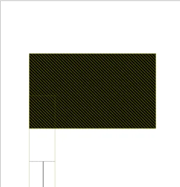
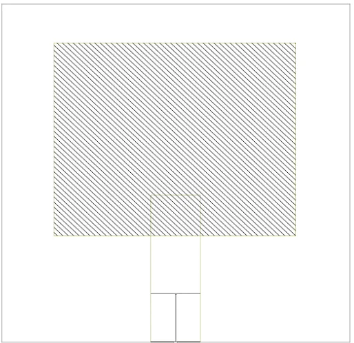
The transmission line is at the center of the width of the patch antenna as seen in Figure 2. With the dimension of the proposed antenna and the length of transmission line at 15.2 mm, return loss of -8.832 dB and VSWR 2.229 can be achieved as seen in Figure 3 (a) and (b).
Figure 2 The proposed antenna with the length of the transmission line at 15.2 mm
1 1
L
=14
mm
293
Figure3 (a) The proposed antenna with Figure3 (b) The proposed antenna
return loss of -8.832 dB with VSWR 2.229 From Figure 3 (a) and (b), the standard minimum of return loss and VSWR from the proposed antenna to create dual frequency operation cannot be reached and the antenna cannot work at frequency 5.1 GHz. After the length of the proposed antenna reduced to 17 mm, a shifted frequency will be occured and the antenna can be able to work at frequency 5.1 GHz. Return loss of – 17.68 dB and VSWR 1.303 can be achieved as
According to the results at Figure 4 (a) and (b), with this position we can use it as a refence to the next itteration.
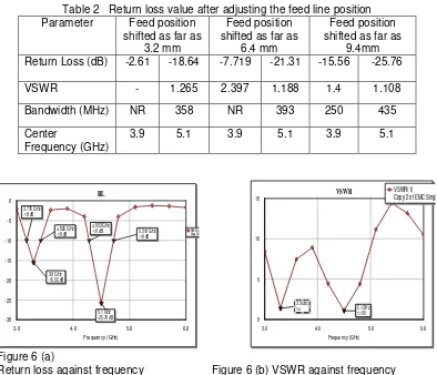
To create dual frequency operation for the proposed antenna is by setting the length of the feeding line as seen in Table 1 and Figure 5 (a) and (b) and then adjusting the feed line position of the proposed antenna. Return loss of -15.56 dB and VSWR 1.4 at frequency 3.9 GHz and return loss of -25.76 dB with VSWR 1.108 at frequency 5.1 GHz can be Copy of EMC Single
294
Figure 5 (a)Return loss after adjusting the Figure 5 (b) VSWR after adjusting the length of the feeding line length of the feeding line
Table 2 Return loss value after adjusting the feed line position Parameter Feed position
shifted as far as
Frequency (GHz)
3.9 5.1 3.9 5.1 3.9 5.1
Figure 6 (a)
Return loss against frequency Figure 6 (b) VSWR against frequency after adjusting the feed position after adjusting the feed position
295
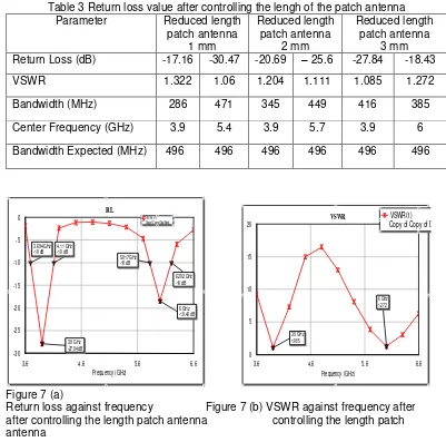
Table 3Return loss value after controlling the lengh of the patch antenna
Parameter Reduced length
patch antenna 1 mm
Reduced length patch antenna
2 mm
Reduced length patch antenna
3 mm adjusting the feed position and controlling the length patch of the antenna and the results parameters can be seen in Table 4.
Table 4 Parameters result of the proposed antenna
Parameter First
Design
Characterization feed point
Characterization length patch antenna
Center Frequency (GHz) 5.1 3.9 5.1 3.9 6
Return Loss (dB) -17.68 -15.56 -25.76 -27.84 – 18.43
VSWR 1.303 1.4 1.108 1.085 1.272
Bandwidth (MHz) - 250 435 416 385
The proposed antena cannot be able to require the range frequency in amount of 496 GHz as expected from the frequency range of the uplink at 3.702 GHz up to 4.198 GHz and downlink at 5.927 GHz up to 6.423 GHz. Table 4 shown that impedance bandwidth for the first frequency is 416 MHz or about 83.8% and the second frequency is 385 MHz or about 77.6%. Copy of Copy of Dual Band
296
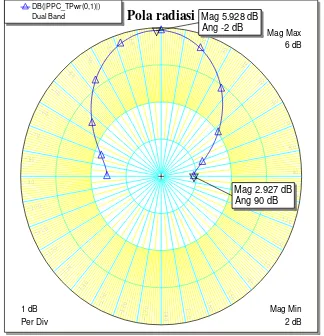
Figure 8 shown theinput impedance and Figure 9 shown the broadside radiation pattern of the proposed antenna.
Figure 8
Input impedance of the proposed Figure 9 Radiation pattern of the proposed
Antenna antenna
4. Conclusion
A novel configuration to excite dual frequency operation for Satellite application using microstrip line has been experimentally studied.It is shown that the two frequencies can be easily controlled by varying the length patch antenna and adjusting the feed position and also the length of the microstrip feed line. It is observed that return loss of -27.84 dB with VSWR 1.085 can be achieved for the first frequency at 3.9 GHz and the impedance bandwidth is about 416 MHz or 83.8%. For the second frequency is at 6 GHz with return loss of -18.43 dB and VSWR 1.272 has the impedance bandwidth of 385 MHz or 77.6%. Therefore the proposed antenna is applicable as a new candidate for dual frequency antenna microstrip for Satellite application.
References
[1] Maci, S and G.B.Gentili, “Dual Frequency Patch Antennas”, IEEE Antennas and Propagation
Magazine, Vol.39, No.6, December 1997
[2] Surjati, Indra, “Dual Frequency Operation Triangular Microstrip Antenna Using A Pair Of Slit”,
11th Asia Pasific Conference on Communications, Perth, Western Austarlia, Oktober 2005
[3] Surjati, I, Yuli KN and Bramantyo S, “Dual Band Microstrip Antenna Using Slot Fed by
Electromagnetic Coupling”, Proceeding Quality of Reaserch, University of Indonesia, August,
2009
[4] Roy,J.S, et al, “New Dual Frequency Microstrip Antenna for Wireless Communication”,
Romanian Journal of Information Science and Technology, Volume 10, Number 1, 2007
[5] El-Tager, A.M, et al, “A Circularly Polarized Dual Frequency Square Patch Antenna for TT&C
Satellite Application”, Progress in Electromagnetic Reaserch Symposium, Beijing, China,
March, 2009
[6] Rahardjo,E.T, “Studies On The Microstrip Antennas Fed By Electromagnetic Coupling“,
Doctoral Thesis, Saitama University, 1996