International Journal of Physical and Mathematical Sciences
journal homepage: http://icoci.org/ijpms
PRELIMINARY STUDY – ANALYTICAL APPROACH IN EXPERIMENTAL RIG OF AUTOMOTIVE
FLEXIBLE WIPER SYSTEM
M.A.Salim*, N.A.I.H.Nik Ab Rashid, F.A.Munir, M.R.Mansor, N.Razali, M.N.N.Rashid, M.R.M.Zin, M.I.M.Azmi
Faculty of Mechanical Engineering, Universiti Teknikal MalaysiA Melaka, Hang Tuah Jaya, 76100 Durian Tunggal, Melaka, Malaysia
E-mail: [email protected]
RECEIVED DATE (2011-3-13)
Abstract
In this study, experimental rig of automotive wiper System is designed and analyzed using numerical
tool. Generally, this rig utilizes different types of electric motor as a power assist. In addition, a suitable
dimension and material for each part was chose for the rig. There are two main considerations in order
to design the experimental rig. The first consideration is the selection of power assist (electric motor)
and the second is the consideration made pertaining to the criteria the design method. In research
methodology, the design and materials used in this study is needed to be structurally analyzed using
analytical calculation. After the calculation is complete and the desired results is obtained, then only the
experimental rig of automotive wiper system can be fabricated and tested. The platform of the rig was
analyzed to identify the external forces acting on the rig. Structural finite element analysis is conducted
on the completed a best design. It is to ensure the rig has a safety factor during the experiment going
on.
Key words: Wiper system, finite element, analytical, numerical
.
Introduction
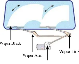
Windscreen wipers are the essential components to a vehicle. It function is to provide good vision to the driver during rains. Nowadays, almost all automobiles are equipped with windscreen wiper which is one of the legal requirements. Clear vision for the car driver is an important safety aspect in road traffic. A conventional wiper is shown in Figure 1. A wiper system is consists of an arm which rotating at a pivot point at one end. This arm is has a long rubber or silicone blade attached together. The function of the blade is to swing back and forth over the windscreen which consequently removes water drops from windscreen surface. The mechanical structure of the wiper blades is attached to the arm tips, holds the rubber blade, which drains the water off the windscreen or to smooth the water on the surface of the windscreen in order to create a thin film that allows light to pass through it without refracting or bending as shown in Figure 2.
Figure 1: Wiper system on a windscreen Wiper Arm
Wiper Motor Wiper Blade
Figure 2: Load distribution of a wiper blade (Denso, 2008)
It is very often that the windscreen wiper generates unwanted and annoying noise and vibration. As stated by Goto et al. (2001), the noise and vibration can be categorized into three types [1]. The categories are squeal noise, chattering and reversal noise. The first type which is squeal noise has a high frequency of vibration up to 1000 Hz. On the other hand, chattering or beep noise is noise occurs at low-frequency vibration of 100Hz or less. Futhermore, an impact sound with a low-frequency of 500 Hz is defined as reversal noise. Impact sound is produced when the wiper reverses. Goto et al. (2001) also added that these types of noise and vibration can lead to visual and audible annoyance for the driver and passengers [1].
There are numerous studies conducted to investigate noise and vibration of an automotive wiper system. Those studies were conducted by using analytical, numerical and experimental approaches. Okura et al. (2000) in his study had performed dynamic analysis of blade reversal behaviors by using a 2-dimensional (2D) mechanical model of a wiper system and a spring-mass model of an arm and blade [2]. Apart from that, in their different works, further studies of the dynamic analysis by using a complete 3-dimensional (3D) model were successfully delivered. Okura et al. (2000) had made comparison between the 2- and 3- dimensional model for the arm and blade [2]. They have suggested in the results that the 3D model could simulate the reversal behaviour of the wiper system more accurately than the 2D model.
Investigation to minimize squeal noise by using a mathematical model had been proposed in (Goto et al, 2001a; Goto et al, 2001b) [1], [3]. In their studies, physical properties and design of the blade were varied. In order to validate the simulated results, experiments on squeal noise were also carried out to verify the effectiveness of the proposed material and design changes. Moreover, an excellent work had been done by Grenouillat et al. (2002) who combined approach [4]. In their work, wiper motion tests were carried out on a developed test rig. Different attack angles and pressure were used and their effect on the wiper motion was observed. Grenouillat et al. (2002) also developed a 2D mathematical model to demonstrate the influence of the geometrical configuration of the wiper system on the generation of unstable motion [5].
The application of dither control to stabilize squeal noise in the wiper system has been introduced in Stallaert et al. (2006) [6]. A finite element (FE) model was developed in order to support the optimization of the control configuration. The study showed that with a proposed dither control, wiper squeal noise was effectively suppressed. Finite Element (FE) model is developed to study dynamic instability of a flexible wiper system. Different values of arm forces and attack angles of a rubber blade were selected and simulated to examine their effects on the vibration response of the wiper. The predicted results were close to those obtained in the experiments.
1. Windscreen Wiper System
Windscreen wiper can be defined as a mechanical device that cleans the windshield during raining. The first invented windscreen wipers were operated manually. The driver needs to move a lever inside the car back and forth and this reduces the driver attention and maneuverability. In current design, most vehicles are equipped with electric windscreen wipers. The wipers without fail keep the windscreen clear, moving back and forth across the windscreen in countless times to remove the water away.
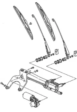
Fig. 3 Wiper system (Porsche-parts, August 3, 2010)
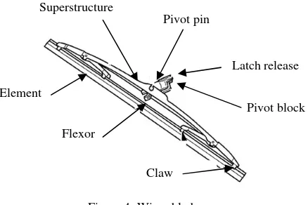
[image:2.612.239.369.496.685.2]Figure 4: Wiper blade
The aerodynamic properties of the wiper blades have become increasingly important due to the design of the vehicle as different air currents flow on and around the screen area. The strip on top of the rubber element is often perforated to reduce air drag. A good quality blade will have a contact width of about 0.1mm. The lip wipes the surface of the screen at an angle of about 45°. The pressure of the blade on the screen is also important as the coefficient of friction between the rubber and glass can vary from 0.8 to 2.5 when dry and 0.1 to 0.6 when wet condition.
There are two types of wiper blade which is rubber and silicone. Wiper blades function like squeegees. A thin rubber strip is dragged by the arms of the wiper across the windscreen to remove away the rain water. The rubber strip is clean without element of crack or nicks when it is new. Hence, it able to remove water without producing streaks. However, as the wiper blades getting older, there will be formation of nicks or cracks. Consequently, road grime builds up on the edge as it does not make as tight a seal against the windscreen. This will lead to the wiper leaves streaks. The lifetime of the rubber wiper blade can be prolonged a little bit by wiping the edge with a cloth soaked in window cleaner until no more dirt comes off the blade.
2. Research Methodology i. Design Specifications
Design specifications are very important in a design process because it provides precise and explicit information about requirements for a product design. Besides that, it consist the best solution to produce this project or design. Through design specifications, it will help engineers and researchers to understand the problem and demerits of the existing design before the design is improved. There are several aspects in design specifications which are:
i. Appearance ii. Geometry limitation iii. Dimension iv. Product
v. Endurance ii. Parts Selection
A material or part selection is an important aspect of design for mechanical, electrical, thermal, chemical or other applications. Systematically, selection of the best material for any application begins with properties, cost of materials and specifications needed. Thus, comparison between each material and part is important step to be considered. For this study, there are three parts that needed to be considers before the right part and material usage will be choose. There are:
i. Strength
Strength can be related to the crash worthiness or general durability of the platform table. However, strength has no effect on the wiper system properties. Apart from that, strength is determined by a property of the material which is called yield strength. The factors that affects the yield strength property is the quality, heat treatment and alloying elements used in a particular brand of tubing.
ii. Stiffness
Stiffness affects the strength of the stand to support the wiper system including windscreen. Elastic modulus is the determinant of stiffness. In a particular metal, elastic modulus is an independent property that can affect the quality or alloying elements. Nevertheless, all kind of steel has the same modulus of elasticity.
iii. Weight (specific gravity)
Specific gravity is an indication how much the strength and stiffness of a material is affected if the volume is added. The specific weight of a given metal is not significantly affected by the addition of different alloying elements.
Superstructure
Pivot pin
Latch release
Pivot block
Claw Flexor
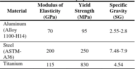
Table 1: Material properties Material
Modulus of Elasticity
(GPa)
Yield Strength
(MPa)
Specific Gravity (SG) Aluminum
(Alloy
1100-H14) 70 95 2.55-2.8
Steel (ASTM-A36)
200 250 7.48-7.9
Titanium 115 830 4.54
According to Table 1, there are three common materials for platform of the rig. The common material for table of rig is aluminum, steel and titanium. The selections of this material are based on material properties as shown in the table. The aluminum frame will be only 1/3 as stiff as steel and the titanium only half as stiff compare to steel. If the strength were considers, the yield strength is very important. Finally, the specific gravity values show that the aluminum frames would only weight 1/3 compares to steel and titanium frame. However, any of these materials is quite suitable for table of rig but if we consider the cost, titanium is not suitable because it costly compare to steel and aluminum. Thus, the comparison between all this materials is analyzed to get the best design and material use. The final material selected is aluminum because of cost and the modulus of elasticity and yield strength still cover the load.
iii. Design With Computer Aided Design (CAD)
It is important to understand the usages, functions, commands, features and many more of numerical tools. This tool is a state of the art 3-dimensional (3D) mechanical CAD program that runs on high processor. CAD is used to design and develop p r o d u c t s , which can be g o o d s used by end consumers or intermediate goods used in other products. CAD is also extensively used in the design of tools and machinery used in the manufacture of components. CAD is also used in the d r a f t i n g and design of all types of b u i l d i n g s , from small residential types (houses) to the largest commercial and industrial types (hospitals and factories). It is used throughout the engineering process from conceptual design and layout, through detailed engineering and analysis of components to definition of manufacturing method. Each of the different types of CAD systems requires the operator to think differently about how he will use them and he must design his virtual components in a different manner for each. Thus, based on conceptual design and brain sketching, the final design will be drawing by using CAD software.
i. Finite Element Method (FE)
The procedure is shown as follows: a. Discretization of the domain
b. Selection of a proper interpolation model
c. Derivation of elements stiffness matrices and load vectors
d. Assemblage of elements equation to obtain the overall equilibrium equations e. Solution for unknown field variable (integration of boundary condition) f. Computation of elements strain and stresses.
For computation of element of beam, the formula used:
Where,
F = Internal force
A = Area acting on the force E = Young Modulus L = Length between nodes U = Deflection
3. Results and Discussion
Figure 5: Final design of experimental rig
[image:5.612.215.398.285.393.2]After each part is assigned to its material properties, the parts are then assembled. After the assembly is done the analysis procedures are assigned in step module. Defining the boundary condition is also done under the step module. Next, the interactions between the parts are defined. Then the meshing is done, the 3D stress element type is used for the whole model. Tetrahedral meshing was used to most of the parts except the windscreen and the rail spring. These two parts were assigned hexahedron elements. Hexahedron element can only be used on simple geometry where else tetrahedron element can be used to mesh complex geometries. Finally the job is created and submitted for analysis.
Figure 6: Dimension of experimental rig table
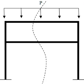
Figure 7: Free Body Diagram (FBD) of experimental rig table
[image:5.612.235.378.430.574.2]Figure 8: FBD after consider the distribution load and symmetry with number of nodes The boundary conditions of the system are:
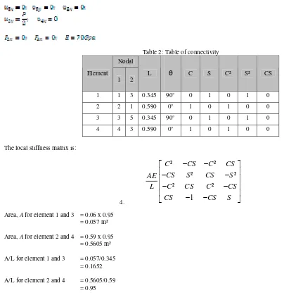
Table 2: Table of connectivity Nodal
Element
1 2
L Ѳ C S C² S² CS
1 1 3 0.345 90° 0 1 0 1 0
2 2 1 0.590 0° 1 0 1 0 0
3 3 5 0.345 90° 0 1 0 1 0
4 4 3 0.590 0° 1 0 1 0 0
The local stiffness matrix is:
4.
²
²
²
²
²
²
1
C
CS
C
CS
CS
S
CS
S
AE
C
CS
C
CS
L
CS
CS
S
−
−
⎡
⎤
⎢
−
−
⎥
⎢
⎥
⎢
−
−
⎥
⎢
−
−
⎥
⎣
⎦
Area, A for element 1 and 3 = 0.06 x 0.95
= 0.057 m²
Area, A for element 2 and 4 = 0.59 x 0.95
= 0.5605 m²
A/L for element 1 and 3 = 0.057/0.345 = 0.1652 A/L for element 2 and 4 = 0.5605/0.59
[image:6.612.49.453.256.682.2]For element 1,
1x 1y 3x 3y
u
u
u
u
0
0
0
0
0
1
0
1
0
0
0
0
0
1 0
1
AE
L
⎡
⎤
⎢
−
⎥
⎢
⎥
⎢
⎥
⎢
−
⎥
⎣
⎦
1 1 3 3 x y x yu
u
u
u
1x 1y 3x 3y
u
u
u
u
0
0
0
0
0
0.1652
0
0.1652
0
0
0
0
0
0.1652
0
0.1652
E
⎡
⎤
⎢
−
⎥
⎢
⎥
⎢
⎥
⎢
−
⎥
⎣
⎦
1 1 3 3 x y x yu
u
u
u
For element 2,
2x 2y 1x 1y
u
u
u
u
1
0
1 0
0
0
0
0
1 0
1
0
0
0
0
0
AE
L
−
⎡
⎤
⎢
⎥
⎢
⎥
⎢
−
⎥
⎢
⎥
⎣
⎦
2 2 1 1 x y x yu
u
u
u
2x 2y 1x 1y
u
u
u
u
0.95
0
0.95 0
0
0
0
0
0.95 0
0.95
0
0
0
0
0
E
−
⎡
⎤
⎢
⎥
⎢
⎥
⎢
−
⎥
⎢
⎥
⎣
⎦
2 2 1 1 x y x yu
u
u
u
For element 3,
3x 3y 5x 5y
u
u
u
u
0
0
0
0
0
1
0
1
0
0
0
0
0
1 0
1
AE
L
⎡
⎤
⎢
−
⎥
⎢
⎥
⎢
⎥
⎢
−
⎥
⎣
⎦
3 3 5 5 x y x yu
u
u
u
3x 3y 5x 5y
u
u
u
u
0
0
0
0
0
0.1652
0
0.1652
0
0
0
0
0
0.1652
0
0.1652
For element 4,
4x 4y 3x 3y
u
u
u
u
0.95
0
0.95 0
0
0
0
0
0.95 0
0.95
0
0
0
0
0
E
−
⎡
⎤
⎢
⎥
⎢
⎥
⎢
−
⎥
⎢
⎥
⎣
⎦
1 1 3 3 x y x yu
u
u
u
4x 4y 3x 3y
u
u
u
u
0.95
0
0.95 0
0
0
0
0
0.95 0
0.95
0
0
0
0
0
E
−
⎡
⎤
⎢
⎥
⎢
⎥
⎢
−
⎥
⎢
⎥
⎣
⎦
1 1 3 3 x y x yu
u
u
u
For global stiffness matrix apply the boundary condition is,
1 1 1 1 2 2 3 3 3 3 4 4
0.95
0
0
0
0
0
0
0.1652
0
0
0.1652
0
0
0
0
0
0
0
0
0
0
0.95
0
0
0
0.1652
0
0
0.3304
0
0
0
0
0
0
0
x x y y y y x x y y y y
F
u
F
u
F
u
E
F
u
F
u
F
u
⎧
⎫
⎡
⎤
⎡
⎤
⎪
⎪
⎢
−
⎥
⎢
⎥
⎪
⎪
⎢
⎥
⎢
⎥
⎪
⎪
⎢
⎥
⎢
⎥
⎪
⎪ =
⎢
⎥
⎨
⎬
⎢
⎥
⎢
⎥
⎪
⎪
⎢
⎥
⎢
⎥
⎪
⎪
⎢
−
⎥
⎢
⎥
⎪
⎪
⎢
⎥
⎢
⎥
⎪
⎪
⎣
⎦
⎩
⎭
⎣
⎦
By solving the equation, the results are:
According to the results in equation (2) until (7), the unknown can be assumed depending on the design criterion made. The force apply on the experimental rig table is consider unknown. That means, the strength of the table
4. Conclusion
The design of experimental rig table is completed using finite element method. There are some problems to get the best design and suitable concept for development of this study. However, the problem was successfully overcome after a few hand sketching and by the combination of different method of attaching mechanism. The 3D view of this design had been drawn by using numerical tool. The dimension of the experimental rig in the drawing is approximated to the real dimensions. Then, the shape and functioning method is same. By referring to this design, the prototype and the analysis of this study will make to study the noise and vibration level on this particular system for further study.
5. Acknowledgement
6. References
[1] Shinya Goto, Hiroshi Takahashi, Takio Oya, “Clarification of Mechanism of Wiper Blade Rubber Squeal Noise Generation”, Journal of Society of Automotive Engineers, Review 22, 2001, pp 57-62.
[2] Shigeki Okura, Tohru Sekiguchi, Takio Oya, “Dynamics analysis of blade reversal behavior in a windshield wiper system”, The Engineering Society for Advancing Mobility Land Sea Air and Space (SAE), 2000.
[3] Shinya Goto, Hiroshi Takahashi, Takio Oya, “Investigation of wiper blade squeal reduction measures”, Society of Automotive Engineers, 2001.
[4] R. Grenouillat, C. Leblanc, “Simulation of mechanical pressure in a rubber-glass contact for wiper systems”, SAE Technical Paper,2002, 2002-01-0798.