PC BASED PROTECTION SCHEME
Mohd Fazrin Bin Mohd Fauzi
Bachelor of Electrical Engineering (Industrial Power)
ii
“I hereby declared that I have read through this report entitle “PC-Based Protection Scheme” and found that it has comply the partial fulfillment for awarding the degree of Bachelor of Electrical Engineering (Industrial Power)”
Signature : ………
Supervisor’s Name : HENDRA BIN HAIRI
PC-BASED PROTECTION SCHEME
MOHD FAZRIN BIN MOHD FAUZI
A report submitted in partial fulfillment of the requirements for the degree of Electrical Engineering (Industrial Power)
Faculty of Electrical Engineering
UNIVERSITI TEKNIKAL MALAYSIA MELAKA
iii
I declared that this report entitle “PC-Based Protection Scheme” is the result of my own research except as cited in the references. The report has not been accepted for any degree and is not concurrently submitted in candidature of any other degree.
Signature : ………
Name : MOHD FAZRIN BIN MOHD FAUZI
iv
v
ACKNOWLEDGEMENT
Firstly of all, I would like to express my deepest thank and gratitude to ALLAH S.W.T who gave me spirit, strength and ability throughout the duration of my final year project. I would like to express my sincere appreciation and gratitude to my supervisor, Mr Hendra Bin Hairi for his constructive guidance and valuable advice during this very challenging moment to complete this final year project.
My experience at Universiti Teknikal Malaysia Melaka is especially rewarding and helpful in my future career because of this supports not only in the research work but also in many other aspects. I would also like to express my gratitude and appreciation to all my friends, BEKP colleagues for the never ending encouragement, moral support and patience during the duration of this final year project.
vi
ABSTRACT
vii
ABSTRAK
viii
TABLE OF CONTENTS viii
LIST OF FIGURE xi
2.3 Power System Protection 7
2.3.1 Overcurrent Protection 8
3 METHODOLOGY
3.1 Overall Planning 9
ix
CHAPTER TITLE PAGE
3.3 Literature Review 11
3.4 Hardware Architecture 11
3.4.1 Circuit Design 11
3.4.2 Primary Circuit Hardware 12
3.4.3 Function of Equipment 13
3.4.4 Fault Simulation 14
3.4.5 Fault Simulation Design 15
3.4.6 Fault Simulation via MultiSim 15
3.4.8 Alternative Fault Simulation 16
3.4.8 Communication Infrastructural 16
3.5 Software Architecture 17
3.5.1 LabVIEW 17
3.5.2 Assesment Input and Output 18
3.5.3 Graphical User Interface 18
3.5.4 Programming 18
3.6 Interface and Operational Test 19
3.7 Final Report 19
4.3.2 Instrumentation Circuit 27
x
CHAPTER TITLE PAGE
4.4.5 Energy Demand History 38
4.4.6 Fault Information 39
4.5 Web Based Monitoring 40
5 ANALYSIS
5.1 Interfacing of Software and Hardware 42
5.2 Operational Test 43
5.2.1 At normal condition 43
5.2.2 During Faulty condition 48
6 CONCLUSION
6.1 Conclusion 51
6.2 Recommendation 52
REFERENCES 53
xi
LIST OF FIGURE
FIGURE TITLE PAGE
2.1 Relationship between measurement, information 6
and decision making
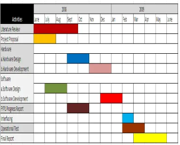
3.1 Gantt chart of overall project planning 10
3.2 Project activities flow chart 11
3.3 Flow chart of Literature Review Process 12
3.4 Flow Chart of Hardware Architecture 13
3.5 Overcurrent protection principle 14
3.6 Normal condition circuit 16
3.7 Short-circuit condition circuit 16
3.8 Fault Simulation Design 17
3.9 Current Injector 17
3.10 Flow Chart Software Architecture 19
3.11 Flow Chart of Software Programming 21
4.1 Basic Architecture of the system 23
4.2 Primary Circuit Schematic 24
4.3 Actual Set-up for Primary Circuit 24
4.4 Current Transformer 25
4.5 Overcurrent Relay 26
4.6 Molded Case Circuit Breaker 27
4.7 Instrumentation Circuit Schematic 27
4.8 Actual Set-up for Instrument Circuit 28
4.9 DAQ Card 6008 28
4.10 Current Sensor 29
4.11 Control Circuit 29
4.12 Actual Set-up for Control Circuit 30
xii
FIGURE TITLE PAGE
4.14 SPDT 5V Relay 31
4.15 Overview of Programming Code 31
4.16 Overall User Interface 32
4.17 Single-Line Diagram 33
4.18 Single-Line Diagram Source Code 33
4.19 Operational Control 34
4.20 Operational Control Source Code 34
4.21 Acquisition Control 35
4.22 Acquisition Control Source Code 35
4.23 Data Acquisition 36
4.24 Energy Demand History 37
4.25 Fault Information 38
4.26 Web Based Monitoring System 39
5.1 Interface between injector and hardware 40
5.2 Interface between hardware and PC (software) 41
5.3 Secondary current monitor from relay (normal) 42
5.4 Breaker Status (ON) 42
5.5 Normal condition system monitored via software 43
5.6 Energy Demand History monitoring. 44
5.7 Recorded Energy Data 45
5.8 Graph form recorded data. 46
5.9 Secondary current monitor from relay (fault) 46
5.10 Breaker Status (OFF) 47
xiii
LIST OF APPENDICES
APPENDIX TITLE PAGE
A Low-Cost, Bus-Powered Multifunction 52
DAQ for USB
B Data Sheet for Current Sensor 57
CHAPTER 1
INTRODUCTION
1.1 Introduction
Power supply is one of the most important resources to the human society development [1]. The cost of power outage is on the order of millions of ringgit. However, power system can become vulnerable in the face of possible system abnormalities such as control, protection or communication system failures, disturbances and human operation errors [2].Therefore, to keep power supply stable and reliable is a very critical issue for power systems design.
In January 2005, a massive breakups of the transmission lines on the East Coast of Malaysia [3] system cost up billion ringgit direct and indirect loss. The incidents demonstrated the importance of real time information for the control system strategy design. Real time can be highly valuable information source for automatic control to maintain system stability. It can also be used as a guide to immediate operating decisions in support of system recovery and for extensive analysis.[4][5]
As the electric power industry enters the new century, new services are compelling electric utilities to make dramatic changes in the power system information infrastructure design. Expanding network services such as real time monitoring are also compelling the need for more increasing bandwidth in the communication network backbone. These needs will grow further as new remote real-time protection and control applications become more feasible and pervasive[6].
2
Applications from SCADA (Supervisory Control and Data Acquisition System) system, remote measurement, to monitoring, and control, protection, are critical to the proper operation of power system in order to maintain system reliability and stability [8].
1.2 Project Objectives
The major objectives of the study are to implement the SCADA application in a power system protection scheme; develop a protection scheme model and a PC-based system communication infrastructure to associate with model’s real-time information. The main research topics are summarized as follows:
1. To design a protection scheme hardware.
Hardware of protection scheme will be design; this hardware will be used as monitored system by SCADA software.
2. To develop software that can be use to monitor and control the protection
scheme.
This software is developed to apply the actual concept of SCADA that had been used in industry. This software must have ability to monitor and control the hardware of protection scheme that will be design also.
1.3 Project Scope
1. The hardware for the system is a overcurrent protection.
2. The software will be used for;
a. Monitoring
i. Current and voltage reading
ii. Position and status of Breaker (open/close)
iii. Trip Indication and Location
iv. Fault Information
3
b. Supervisory Control
i. Breaker operation (trip/reset)
ii. Acquisition speed
1.4 Problem Statement
1. Traditionally, measurements are done on instruments of various
types-oscilloscopes, multi meters, counters etc. However, the need to monitor the measurements and process the collected data for visualization has become increasingly important.
2. The demand to gather reliable and instant information in power systems have
greatly increased. Requirements to remotely monitor and control the power system operation becoming more important. With this ability, operator can respond instantaneously thus improving the power system performance.
1.5 Project Arrangement
In general, there are 6 chapters in this project report. Some basic principle, theories, design, result and discussion are included in this 6 chapter based on content requirement for each chapters.
Chapter 1 is the introduction of the research project. Overview and the main objective of this project will explain in this chapter. This chapter also will explain about scope and problem statement for this project.
4
Chapter 3 is the methodology chapter for this project. In this chapter all the step or method that used in this project will be explain in detail. The designing process also will be covered in this chapter.
Chapter 4 and Chapter 5 is and very crucial chapter. Chapter 4 is a result chapter while chapter 5 is the analysis for the result gain. The entire finish product on the project will be shown in figure in these 2 chapters.
CHAPTER 2
LITERATURE REVIEW
2.1 Real Time Value
Real time date can be highly valuable information source for automatic control to maintain system stability. It can also be used as a guide to immediate operating decisions in support of system recovery and for extensive analysis [9]. According to the research [1], the widespread power outage in the western United States on 10 August 1996 could have been avoided if 0.4% of the wide area loads had been shed for 30 minutes. The 1996 breakups as well as other outages demonstrate that wide area, comprehensive and real time information exchange is becoming a critical factor for the future power system reliability and stability.
6
Figure2.1: Relationship between measurement, information and decision making
2.2 SCADA
SCADA is an acronym that stands for Supervisory Control and Data Acquisition. SCADA refers to a system that collects data from various sensors at a factory, plant or in other remote locations and then sends this data to a central computer which then manages and controls the data. [8]
SCADA is a term that is used broadly to portray control and management solutions in a wide range of industries. Some of the industries where SCADA is used are Water Management Systems, Electric Power, Traffic Signals, Mass Transit Systems, Environmental Control Systems, and Manufacturing Systems [8].
2.2.1 SCADA as a System
7
entire central system. The central system usually monitors data from various sensors that are either in close proximity or off site (sometimes miles away) [8].
For the most part, the brains of a SCADA system are performed by the Remote Terminal Units (sometimes referred to as the RTU). The Remote Terminal Units consists of a programmable logic converter. The RTU are usually set to specific requirements, however, most RTU allow human intervention, for instance, in a factory setting, the RTU might control the setting of a conveyer belt, and the speed can be changed or overridden at any time by human intervention. In addition, any changes or errors are usually automatically logged for and/or displayed. Most often, a SCADA system will monitor and make slight changes to function optimally; SCADA systems are considered closed loop systems and run with relatively little human intervention [8].
One of key processes of SCADA is the ability to monitor an entire system in real time. This is facilitated by data acquisitions including meter reading, checking statuses of sensors, etc that are communicated at regular intervals depending on the system. Besides the data being used by the RTU, it is also displayed to a human that is able to interface with the system to override settings or make changes when necessary.
2.2.2 User Interface
A SCADA system includes a user interface, usually called Human Machine Interface (HMI) or Graphical User Interface (GUI). The HMI of a SCADA system is where data is processed and presented to be viewed and monitored by a human operator. This interface usually includes controls where the individual can interface with the SCADA system [11].
2.2.3 SCADA Software and Hardware Components
8
large applications such as monitoring and controlling a system.
SCADA can come in open and non proprietary protocols. Smaller systems are extremely affordable and can either be purchased as a complete system or can be mixed and matched with specific components. Large systems can also be created with off the shelf components. SCADA system software can also be easily configured for almost any application, removing the need for custom made or intensive software development [11].
2.3 Power System Protection
Power system protection is that part of electrical power engineering that deals with protecting the electrical power system from faults by isolating the faulted part from the rest of the network [12].
The main objective of a protection scheme is to keep the power system stable by isolating only the components that are under fault, whilst leaving as much of the network as possible still in operation. Thus, protection schemes must apply a very pragmatic and pessimistic approach to clearing system faults. For this reason, the technology and philosophies utilized in protection schemes are often old and well-established because they must be very reliable [13].
Protection systems usually comprise five components:
1. Current and voltage transformers to step down the high voltages and currents of
the electrical power system to convenient levels for the relays to deal with;
2. Relays to sense the fault and initiate a trip, or disconnection, order;
3. Circuit breakers to open/close the system based on relay and autorecloser
commands;
4. Batteries to provide power in case of power disconnection in the system.
5. Communication channels to allow analysis of current and voltage at remote
9
2.3.1 Overcurrent Protection
Protection against excess current was naturally the earliest protection system to evolve [14]. From this basic principle, the graded overcurrent system, a discriminative fault protection, has been developed. This should not be confused with ‘overload’ protection, which normally makes use of relays that operate in a time related in some degree to the thermal capability of the plant to be protected [15]. Overcurrent protection, on the other hand, is directed entirely to the clearance of faults, although with the settings usually adopted some measure of overload protection may be obtained. There of 3 type of overcurrent protection relays that’s operates when the faults current is higher than its current setting [14].
1. Instantaneous relay – operates in typically 20ms – 40ms
2. IDMT relays – time delay operation. Delay depends on the current setting,
fault current and time-multiplier setting.
CHAPTER 3
METHODOLOGY
3.1 Overall Planning
A necessary project methodology should be followed to complete this project. Figure 3.1 shows the flow of project methodology in conducting this project. All the schedule activities should be done on time to make sure project is on the right progress and not affecting other activities.