AUTOMATIC STREET LIGHTING CONTROL SYSTEM WITH FAULT CURRENT ANALYSIS
NOR HAFIZAH BT CHE HASSAN
This Report Is Submitted In Partial Fulfillment of Requirements For The Bachelor of Electrical Engineering
(Industrial Power)
Faculty of Electrical Engineering Universiti Teknikal Malaysia Melaka (UTeM)
Specially dedicated to my family…..
In memories, my late Father, Allahyarham Che Hassan bin Che Soh Dearest Mother, Rafeah Yusoh,
ACKNOWLEDGEMENTS
First of all, I would like to express my thankfulness and gratitude to Allah S.W.T who has given me all the strength that I needed to complete this final year project and also prepare this report.
With this opportunity, I would like to express my gratitude to the Faculty of Electrical Engineering (FKE), Universiti Teknikal Malaysia Melaka (UTeM) generally, and especially to my supervisor Dr Musse Mohamud Ahmed for this help, advices and guidance that he gave me during this project.
ABSTRAK
ABSTRACT
TABLE OF CONTENTS
CHAPTER TITLE PAGE
TITLE PAGE i
DEDICATION ii
ACKNOWLEDGMENT iii
ABSTRAK iv
ABSTRACT v
TABLE OF CONTENTS vi
LIST OF FIGURES ix
LIST OF TABLE x
LIST OF APPENDICES xi
1 INTRODUCTION
1.1 Definition 1
1.2 Project Overview 2
1.3 Problem Statements 2 1.4 Objective of the Project 2
1.5 Project scope 3
2 LITERATURE REVIEW
2.1 Overview 4
2.2 First Review 4
2.3 Second Review 6
2.4 Third Review 7
2.4.1 Objectives 8
3 PROJECT BACKGROUND
3.1 Project Background 11
3.2 System concept 12
3.3 Software Implementation 13 3.3.1 Indusoft Software 13 3.3.2 Indusoft Software as
Graphical User Interface
(GUI) 16
3.4 Hardware Implementation 17 3.4.1 I-7188XG Controller 17 3.4.2 I-7051 I/O Module 20 3.4.3 DB9 Serial Port 4 RS232 21
4 METHODOLOGY
4.1 Methodology Flowchart 26 4.2 System working concept 27 4.3 Isagraf Software Development 29 4.3.1 Linking to HMI via Modbus 32 4.3.2 Declairing Variable Address
for Network Access 32 4.3.4 Converting Decimal to
Hexadecimal 33
4.4 Modbus network 36
5 RESULTS AND DISCUSSION
5.1 Software Development 38 5.1.1 ISaGRAF Software 38 5.1.2 Indusoft Software 43
5.2 Overall Result 43
5.2.1 Result 44
6 CONCLUSION AND RECOMMENDATION
6.1 Conclusion 46
6.2 Future Recommendation 46 6.2.1 Combination Monitoring
Part and SMS Part 47
REFERENCES 50
GANTT CHART 51
LIST OF FIGURES
FIGURE TITLE PAGE
2.1 ARCNET power line modem 7
2.2 Illustration of outstation 9
3.1 System Concept 12
3.2 I-7188XG Controller 18
3.3 16 Channel Isolated Digital Input Module 21
3.4(a) DB9 Serial Port 4 RS232 23
3.4(b) RS232 25
4.1 Methodology Flowchart 27
4.2 Working Concept 29
4.3 Test I/O Connection 31
4.4 Network Address is set in Hexadecimal 33
5.1 Function block diagram & ladder diagram 39
5.2 Sequential Function Chart 40
5.3 Structural Text & Instruction List 41
5.4 Functional Block Diagram for I/O Module 42
5.5 Monitoring System 43
5.6 Street Lighting Module 45
5.7 DC Supply 45
5.8 Output 45
LIST OF TABLE
TABLE TITLE PAGE
LIST OF APPENDICES
APPENDIX TITLE PAGE
A Hardware Interface 52
B Indusoft Software Application 54
C Conversion Table 56
D DB9 Serial Port 4 RS232 58
CHAPTER I
INTRODUCTION
1.1 Definition
• A Street light, lamp post, street lamp, light standard or lamp standard, is a raised source of light on the edge of a road, turned on or lit at a certain time every night.
• Fault current: current which results from the loss of insulation between conductors or between a conductor and ground.
• The level of current that can flow if a short circuit is applied to a voltage source
• RTU- control system is a device or set of devices to manage, command, direct or regulate the behavior of other devices or systems.
1.2 General Description (project overview)
This SCADA (Supervisory Control And Data Acquisition) analysis project is based on fault current to the automatic street lighting control system. The project has used SCADA (Supervisory Control And Data Acquisition), which is a software using Indusoft and also can link to a controller using IsaGRAF software. SCADA/ HMI sof t ware is used because it runs on everyt hing f rom mobile phones t o PC
workst at ions, handles an unlimit ed number of t ags f or large process cont rol
syst ems, and int erf aces t o high level sof t ware syst ems. Then, t he syst em
int erf aces wit h t he ready made hardware t o run t he program.
1.3 Problem statements
Every day, there is fault which occurs in to our street lighting system. When the fault occurs, TNB workers cannot detect the fault instantaneously, what type of fault and which part the fault occurs. It causes problems for the customers that they could not get the services for several hours and days. At the same time, if any fault occurs it will take a lot of time to maintain it again while the same fault occurs again and again. So, the objectives of this project are to avoid the problem which occurs during the fault and to monitor what type of fault it is. These problems that might be solved using SCADA (Supervisory Control And Data Acquisition) system.
1.4 Objectives of the project
The project is aimed to meet the following objectives: • To study the Isagraf software and Indusoft software • To study how to automate street lighting system
• To study and monitor what type of fault such as over current, earth leakage, or under-voltage.
1.5 Scope of the project
The project scopes for implementations are:
Automatic Street lighting control system is proposed to the street lighting company.
The RTU (Remote Terminal Unit) will be main the controller for the system.
CHAPTER 2
LITERATURE REVIEW
2.1 Overview
This chapter will discuss about sources or articles that related to the project. There are many sources or researches done before and from there, details about this project are known and can understand briefly about the project.
2.2 First Review
In countries such as France, Germany, Belgium, UK and the Northern part of the US, street lamps are burning an average of 4000 hours per year. Considering that the average wattage of a lamp is around 150 watts, considering that a 100,000 inhabitant city contains about 18,000 lamps, such a city spend around 11 giga watt hours (11 billion watt hours). Considering that producing 1 kWh implies the emission of 340 grams of CO2 (average in Europe), the streetlights of such a city are responsible for the emission of 3700 tons of CO2 in the atmosphere per year.
Technologies and techniques now exist to:
1. save electricity without impacting the lighting level perceived by citizens
2. automatically identify 99% of lamp and
3. Leverage the same technologies and the same infrastructure to monitor other environmental data (through temperature, humidity, air pollution, air quality and noise sensors) to build a real-time environmental database and enhance control. 4. by replacing timers and photocells in cabinets with a centrally controlled unit
primarily using savings of 5-8% can be achieved according to experience i can monitor all major problems with the street light (breaker and fuse errors, cable faults and broken bulbs to a certain extent). This reduces maintenance costs significantly and increases the overall light quality.
Amongst the key technologies and techniques:
1. Electronic communicating ballasts (such as SELC ballasts) dim lamps intelligently when less light is required (such as middle of the night in industrial and commercial zones). They consume 4 to 5 watts while magnetic ballasts consume up to 20 watts. In 2005 the European Union voted a directive (2000/55/EC) to incitate Cities to deploy electronic ballast that result in up to 45% electricity savings. Such electronic ballasts can usually identify failures of the lamp and the electrical network and communicate them through protocols such as EIA709 on powerline. EC directive (2000/55/EC) relates ONLY to fluorescent lighting and fluorescent ballasts. This directive has little to do with the vast majority of street lighting ballasts.
There are methods to dim existing magnetic ballasts which also identify failure conditions. There are solutions that will pay back the capital cost for adding controls in 2 and not more than 3 years where street lighting costs range from 12 to 10 euro cents per kilowatt hour and are used 11 to 12 hours a day [6].
2.3 Second Review: Street Public Lighting Control and Monitoring using PLC Communication
There may be tens of thousands of street lamps in the streets and along the highways. To inspect each lamp to check if it is working is an arduous task. Isn't it nice to have a system, which will automatically report if a lamp in a Public Lighting System has broken down? The infrastructure required of such self-reporting function must be very complicated and the cost prohibitively high. Not if you use ARCHNET power line modems.
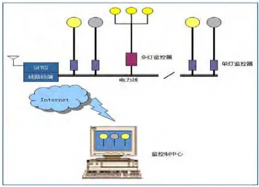
The ARCHNET power line modem makes use of the power cable as a communication medium and data communication can take place between two points on a power line without the need of a dedicated signal wires. An ARCHNET power line modem and a sensor connected at the power source of the street lamp of a public lighting system can sense the current flow through the lamp, thus monitoring the operation of the street lamp. If the lamp breaks down, the modem will report the address code of the lamp report back to the monitoring station through the power cable. At the Public Lighting control station, a signal will flash on the screen giving the location of the street lamp. A repairman can then be sent immediately to the right location to check and replace the bulb.
Center can broadcast an On / Off command at fixed times over the power line to operate street lamps in different zones of a Public Lighting System [7].
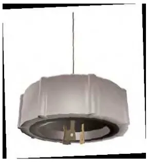
Figure 2.1: ARCHNET power line modem
2.4 Third Review: Remote Street Lighting Monitoring And Control System
Currently, street lights are controlled by photocells. These have only one
function, which is switching lights on and off according to factory-fixed, light-level
thresholds. Telensa's proposed system operates by replacing the traditional photocell
with an 'outstation'. This performs the lamp switching and monitoring functions. It also
contains a small radio, which communicates back to the base station or 'hub'. A large
deployment would have a number of hubs, which themselves would be connected to a
central system computer and database. Switching can be set in various ways, for
2.4.1 Objectives
The objective of this project is to demonstrate a remote street lighting monitoring
and control system that is not only has a wide range of energy saving features, but is also
sufficiently low cost to make it the first commercially viable solution for the market.
The project aims to:
• Show that the innovative radio technology can be used to provide a real, practical and
reliable solution to the needs of the street lighting industry;
• Verify the details of the functionality required, and show that the functionality does
yield the claimed operational and energy saving benefits;
• Show that the product can be produced cost-effectively;
• Clear the regulatory path to enable the use of a metered supply for street lighting;
• Show accuracy and flexibility of lighting control that will enable the elimination of
waste and the 'fine tuning' of burning hours, leading to energy cost savings;
• Show a range of continuously and periodically monitored electrical parameters that can
be used to provide prompt lamp failure notifications and operating performance
statistics;
• Show diagnosis of operating power factor and potential for power factor improvement;
• Meter energy consumption;
• Investigate the practicalities of installation, volume deployment and system set up and
• Explore, understand and prioritize product design features and system functionality for
[image:20.612.255.398.178.336.2]a fully commercial system;
Figure 2.2: Illustration of outstation
2.5 Conclusion
Based on the study that have been done, there are so many technologies and techniques now exist to make the street lighting system become more easier to monitor and control the fault, especially fault current. From the first review, experience in Scandinavi timers and photocells in cabinets with a centrally controlled unit primarily using as communication carrier and a centralized photocell. Furthermore, a communication unit in the cabinet can monitor all major problems with the street light (breaker and fuse errors, cable faults and broken bulbs to a certain extent). This reduces maintenance costs significantly and increases the overall light quality.
sense the current flow through the lamp, thus monitoring the operation of the street lamp. If the lamp breaks down, the modem will report the address code of the lamp report back to the monitoring station through the power cable. At the Public Lighting control station, a signal will flash on the screen giving the location of the street lamp. A repairman can then be sent immediately to the right location to check and replace the bulb.
Based on the third review, the objective of this project is to demonstrate a remote street lighting monitoring and control system that is not only has a wide range of energy saving features, but is also sufficiently low cost to make it the first commercially viable solution for the market.
Currently, street lights are controlled by photocells. These have only one
function, which is switching lights on and off according to factory-fixed, light-level
thresholds. Telensa's proposed system operates by replacing the traditional photocell
with an 'outstation' which contains a small radio, which communicates back to the base
CHAPTER 3
PROJECT BACKGROUND
3.1 Project Overview
This SCADA (Supervisory Control And Data Acquisition) analysis project is based on fault current to the automatic street lighting control system. The project will use SCADA (Supervisory Control and Data Acquisition), which is a software using Indusoft and also can link to a controller using IsaGRAF software. SCADA/ HMI sof t ware is used because it runs on everyt hing f rom mobile phones t o PC
workst at ions, handles an unlimit ed number of t ags f or large process cont rol
syst ems, and int erf aces t o high level sof t ware syst ems. Based on this, if any
Mobile to monitor and also control the fault. Therefore, it will save our time and the work will be easier.
3.2 System Concept
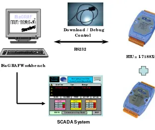
We need to develop both of the software packages and the hardware at the same time because we must interface with them. For ISaGRAF software, we must link it using modbus RS232 to the controller. While for the power analyzer, we must use modbus RS485 to link with the controller as Remote Terminal unit (RTU). But, we found that there was a problem to get the actual street lighting module due to technical problem. So, in this project we are not using power analyzer but we need to use the other hardware such as controller I-7188XG, I/O Module I-7051, DB9 Serial Port 4 RS232, connector and DC Supply.
ISa G RAF Wo rkb e nc h
Do wnlo a d / De b ug C o ntro l
RS232
RTU = I- 7188XG
SCADA System
Time #### Date ####
Street Lighting Control System Universiti Teknikal Malaysia Melaka
Active Time Type Message
! ! ! !
04/14/2008 10:15:23 Lo Zone1_R trip
FILTER COLUMNS PRINT ACT TOP ACT ALL
[image:23.612.191.503.403.665.2]Zone 1 Zone1_R Zone1_Y Zone1_B Zone 1 Zone1_R Zone1_Y Zone1_B Zone 1 Zone1_R Zone1_Y Zone1_B BEEP STATUS Communication to Input Module
In this project, we use I-7188XG controller which is a palm-size ISaGRAF SoftLogic μPAC, supporting popular & easy programming software: ISaGRAF Ver.3. It is default has 2 serial ports (COM1:RS232/RS485 & COM2:RS485) and supports to plug one X-borad to add more ports or I/O channels. The ISaGRAF μPAC supports: Modbus serial protocol, Modbus master protocol, Fbus: RS485, remote I/O, SMS: Short Message Service, modem link, MMICON / LCD and user defined protocol.
3.3 Software Implementation
3.3.1 Indusoft Software
InduSoft Web Studio is the most powerful collection of RACE tools offering Web and wireless integration on the market today. You can use InduSoft Web Studio to create native applications that run on all supported. Windows operating systems and Web-based HMI/SCADA applications – with no other tools required. The simple drag and drop, point and click development environment enables you to mimic the most complex behaviors of your live processes. Use InduSoft Web Studio with the most popular Web Browser to manage workstations; monitor, debug, and update software remotely; and access real-time, dynamic graphic screens, trends/alarms, reports, and recipes online.


