DEFECT INSPECTION SYSTEM FOR SHAPE-BASED
MATCHING USING TWO CAMERAS
1
MARIZAN SULAIMAN, 2 HAIROL NIZAM MOHD SHAH, 3 MOHAMAD HANIFF HARUN,
4 MOHD NOR FAKHZAN MOHD KAZIM
1,2,3 Universiti Teknikal Malaysia Melaka, Faculty of Electrical Engineering, Hang Tuah Jaya, 76100
Durian Tunggal, Melaka, Malaysia
4 Universiti Malaysia Perlis (UniMAP), School of Mechatronic Engineering, Pauh Putra Campus 02600
Arau, Perlis, Malaysia
E-mail: [email protected] , [email protected] , [email protected] ,
ABSTRACT
This research is regarding the application of a vision algorithm to investigates various approaches for automated inspection in of gluing process using shape-based matching application in order to control the decision making concerning jobs and work pieces recognition that are to be made during system operation in real time. A new supervised defect detection approach to detect a class of defects in gluing application is proposed. Creating of region of interest in important region of object is discussed. Gaussian smoothing features in determining better image processing is proposed. Template matching in differentiates between reference and tested image are proposed. This scheme provides high computational savings and results in high defect detection recognition rate. The defects are broadly classified into three classes: 1) gap defect; 2) bumper defect; 3) bubble defect. A new low-cost solution for gluing inspection is also included in this paper. The defects occur provides with information of height (z-coordinate), length (y-coordinate) and width (x-coordinate). This information gathered from the proposed two camera vision system for conducting 3D transformation.
Keywords: Gaussian Smoothing, Recognition Rate, Region of Interest, Shape Matching, Template
Matching.
1 INTRODUCTION
Machine vision has become a key technology in the area of manufacturing and quality control due to the increasing quality demands of manufacturers and customers. Machine vision utilises industrial image processing through the use of cameras mounted over production lines and cells in order to visually inspect products in real time without operator intervention. Machine vision (also called "industrial vision" or "vision systems") is primarily focused on computer vision in the context of industrial manufacturing processes, be it in the inspection process itself (e.g. checking a measurement or identifying a character string is printed correctly) or through some other responsive input needed for control (e.g. robot control or type verification). The machine vision system can
consist of a number of cameras all capturing, interpreting and signaling individually with a control system related to some pre-determined tolerance or requirement.
2 BACKGROUND
In this paper, the most important applications used are shape-based matching using HALCON [1]. This application has the effect that this approach is able to handle changes in illumination, clutter, varying size, position and rotation, or even the relative movement of parts of the template projected, multiple instances can be found and multiple models can be used at the same time.
mapping to high level feature, image classification and image interpretation [2]. The crucial part is on image segmentation which is involved of de-noising technique. The segmentation procedure brings the process a long way toward successful solution of imaging problems that require objects to be identified individually. On the other hand, weak or erratic segmentation algorithms almost always guarantee eventual failure. Image segmentation involves a various type of command that will lead to smoothen of the image as a result for easier execution in recognition system.
There are many techniques that provides a solution in recognizing image or object in image processing such as region [3], edge-based features [4-5], feature extraction [6], shape context [7-8], low distortion correspondences [9] and etc.. The other research is based on HALCON Application for Shape-Based Matching [10-11]. This paper is discuss mostly on the process involved in a basic shape based matching algorithm with additional of extended Region of Interest (ROI) available in HALCON that fulfils shape based matching to find object based on a single model image and locate them with sub pixel accuracy. The basic concept of defect matching using shape-based matching algorithm based on extended region of interest introduced by [1] as shown in Figure 1.
Vision-based inspection of industrial products offers low-cost, high-speed, and high-quality detection of defects. Some of the most challenging industrial inspection problems deal with the textured of the gluing process. Defects are common occurred in gluing process. To make sure the quality of gluing process, defects detection and recognition are most popular application used. Many researchers are mostly focused in welding line and also in fabric and many interesting results have been obtained [13-23]. Roughly, all these researchers can be classified as two types, one is based on radiographic inspection and the others based on artificial intelligence. The first kind of methods is to recognize welding defects manually, so the efficiency is much limited [12-14]. The second kind of methods are much better in efficiency, however the complexity of implementation is unnecessary [15-23].
The other research is focused on the welding defect [19, 23] that uses the feature extraction method to simplify image to a simple algorithm which is based on the perceptron model to recognize and classify the defects according to the data captured from the extraction method. Image of welding line is very important to the feature extraction and defect recognition in order to
recognize and classify the welding defects accurately.
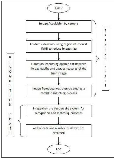
In all the above research, the machine vision system has two common similarities, first is the three basic framework of the process involved; image acquisition, preprocessing and feature extraction. The second one is the two main phase in shape-based matching algorithm which is training and recognition phase. In the above research, it seems that most model based vision programs are developing for a specific task and the environment explicitly coded into the system.
Figure 1: Basic Framework for Matching Application
3 THE PROPOSED SYSTEM
defect occurs contains with location information in x, y and z coordinates.
3.1 Template Matching of Vision Based Defect Inspection
The main idea of this research is to recognize defects after the robot finish perform glue operation according to the specification given by the vision sensor. In order to develop a system that required intelligent in detecting defects, it’s consists with too many techniques can be used but there is a wide range of different algorithm concept that each has its strengths and weaknesses. From all of these algorithms, shape-based matching algorithm was chosen to be used in this research. This is because the requirement of this research is mainly on the inspection of a constant and repetitive type of image. Besides that, because of the wide range of applications that might occurs, shape-based matching which takes only the outline edges of an coordinates known as height (z-coordinate), width (x-coordinate) and length (y-coordinate).
This research are based on HALCON software that provides a wide range of library that will helps mostly on image processing algorithm. This is important and very useful that can be manipulate into the system that meet our requirement. The basic of shape based matching application as shown
in Vision-based inspection of industrial products
offers low-cost, high-speed, and high-quality
detection of defects. Some of the most
challenging industrial inspection problems deal
with the textured of the gluing process. Defects
are common occurred in gluing process. To
make sure the quality of gluing process,
defects detection and recognition are most
popular application used. Many researchers
are mostly focused in welding line and also in
fabric and many interesting results have been
obtained [13-23]. Roughly, all these
researchers can be classified as two types,
one is based on radiographic inspection and
the others based on artificial intelligence. The
first kind of methods is to recognize welding
defects manually, so the efficiency is much
limited [12-14]. The second kind of methods
are much better in efficiency, however the
complexity of implementation is unnecessary
[15-23]. feature extraction and defect recognition in order to recognize and classify the welding defects accurately.
In all the above research, the machine vision system has two common similarities, first is the three basic framework of the process involved; image acquisition, preprocessing and feature extraction. The second one is the two main phase in shape-based matching algorithm which is training and recognition phase. In the above research, it seems that most model based vision programs are developing for a specific task and the environment explicitly coded into the system.
the approximate region is identified, the
Figure 3333 shows the process of Region of interest and saved as defect template for recognition phase.
Figure 2: Project Development
Figure 3: Region of Interest Before and After Process
At the recognition phase, template matching is used by comparing the template image with the process image pixels by pixels by referring to template image saved in the memory. The matching process moves the template image to all possible region its cover according to the template creation. Template matching is robust to noise, clutter, occlusion, and arbitrary non-linear illumination changes. Objects are localized with sub-pixel accuracy in 2D. Before hand, the template of an object must be classified first before used it in recognize similar objects in source image [24].
Figure 4: Template Matching Process Evaluation
According to Figure 4 shows the process evaluation of the template matching by using correlation method in representing relationship between template and source images. Correlation is a measure of the degree to which two variables (pixel values in template and source images) agree,
not necessary in actual value but in general behaviour. In correlation method, results of combination of differences between template gray level image, with average gray level in the with larger values representing a stronger relationship between the two images. Error! Reference source not found. shows the correlation relationship.
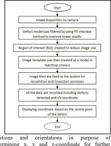
Figure 5: Proposed System Algorithm for Defect Inspection System
3.2 3D Representation (z-Coordinate Transformation)
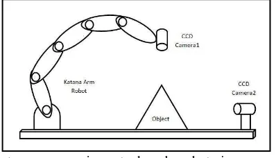
Gluing process involves x, y and z-axis in determining the position according to the working space of the Katana robot arm. In previous experiment, matching process involves one camera placed at the top of the object as a purpose in identifying the object that need to go for gluing process. Renovation of this system is created by applying another camera in front of the object for purpose in reviving the z-coordinate in the image. According to [25] the method used are to find the 3D object recognition defining as x, y and z-axis by using evaluation function in order to determine better position and orientation for camera placement. Figure 6 shows the proposed method by using two cameras from the researcher.
Figure 6: Placement of two Camera of 3D Recognition
Referring to the Figure 6, this configuration has the ability to reproduce the 3D transformation according to the model template that being created in the system. The measurements of the camera takes account all the side of the object which will be process in determining the exact value of transformation with the original. From this application, the development of new proposed method by using two cameras with different
positions and orientations in purpose of determining x, y and z-coordinate for further process in this research. The renovation of this new method being proposed is used in creating a z-coordinate according to the x and y-axis from images captured. Figure 7 shows the new proposed method developed in this research.
Figure 7: Proposed two Cameras Placement in 3D Recognition
Camera placement has been developed according to the needs of the system requirement as described before. The arrangement helps in determini
ng
z-coordinat
e by
applying two-dimensio nal image.
The
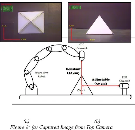
system that involve with 3D transformation all the x, y and z-coordinate must be appointed which means the image should have length, width and height. The transformation of z-coordinate in 3D involves of two images which are taken from both camera, top and front. Before the z- coordinate are determined, two type of image must be taken through the top and front cameras as shown in Figure 8.
(a) (b) Figure 8: (a) Captured Image from Top Camera
(b) Captured Image from Front Camera
Both images are used as a reference images for further process. The first reference image (top camera) will generate the x and y-coordinate. Then the second reference image (front camera) will generate the x and z-coordinate. Both coordinates are generate by using mathematical approach of straight line [26] according to the object specimen that has a shape of rectangle. The calculation between one points to another retrieve all the information needed to be used in pointing another point between the previous two points. Firstly, the system should identify all the edge point within both images. Then, identified the two points needed to be calculated and labelled as (xn-1, yn-1) and (xn,
yn). Then, the points are applied it into the equation
to define the slope of the line in pixels coordinate.
)
/(
)
(
−
−1−
−1=
n n n nn
y
y
x
x
m
(2)After that, value of the slope and point is used in the slope-intercept equation to define the intersection of the line. mn = ( yn - yn-1) / ( xn – xn-1)
y
n=
m
nx
n+
c
n (3)Then, the distance in x-axis and y-axis between two points is calculated and defines it as k and l. The point will then be integrated into Error! Reference source not found. to find new location of the point based on the information obtained. Lastly, new point being declared and classified as one of the point needed in the system. The pointing results of both images are shown in Figure 9.
Figure 9: A New Point Appointed from Top and Front Camera
In applying glue application, the point of each coordinate must be accurate for precise operation. Therefore, the findings of this z- coordinate provide an additional data in order to minimize error of the system. In real operation, the shape of object is not exactly the same as the image taken. So, by providing a mathematical approach of straight line helps in rebuilding the z-coordinate based on their own image taken through the systems. In order to reconstruct 3D image from both 2D images, there are 3 steps to follow respectively.
1. Determining position of camera.
In order to get the exact value from both images, the object captured must be adjusted for obtaining better position from both cameras. Every centimetre different will result to inaccurate size of image. For beginning, set the top and front camera as 50 cm from base. Let the top be constant at 50 cm and front as adjustable in acquiring exact value of x-coordinate for both as shown in Figure 10.
Figure 10: The Proposed of two Camera Placements in 3D Recognition
able to synchronize with the x-coordinate where it’s as a backbone for completing the 3D image construction.
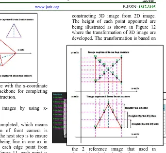
2. Comparing both images by using x-coordinate.
After step 1 completed, which means the exact position of front camera is determined. Then the next step is to ensure that both images being line in one ax in order to compare each edge point from both images. In Figure 11, each point is numbered according to the sequences. Point 1, 5, 6, 7, 8, 9 and 10 from top camera are compared with the same point from the front camera. The x-coordinate should be exactly the same by both images in claiming that the images have the same size and height can be measured through image from front camera.
Figure 11: Integration of two Image Source in Finding New z-coordinate
Measurement of the height (z-coordinate) of each point should be done by using mathematical approach which point 7 and 10 appointed as a reference point. All the data generated will be used as an additional data in doing glue process to ensure the systems work smoothly and efficient.
Height,Hn =Zn−Z7,10 (4)
3. Combining features from both images.
The next step is to combine all data gathered from step 1 and 2 for
constructing 3D image from 2D image. The height of each point appointed are being illustrated as shown in Figure 12 where the transformation of 3D image are developed. The transformation is based on
the 2 reference image that used in determining the height of each point.
Figure 12: Information Gathered from two Sources Images in Generate 3D Image from 2D Image
According to the Figure 12, the development of 3D image are based on x, y and z-plane where it’s consists of length, width and height. This application helps in rebuilding data of 3D image by using two cameras which have their own position and rotation that important in classifying the 3D transformation. Hence, this method is proposed according to the needs of the system in this research.
4. EXPERIMENTAL RESULTS
pixel coordinate in the system. This information is important as the task continuing in correcting all the defects after the matching process done its part. Correction phase consists of Katana arm robot to alter the defects to ensure that glue is in fine shape.
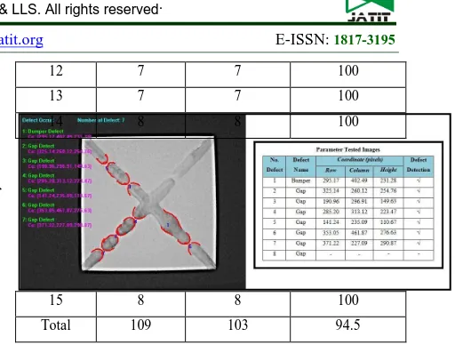
According to the Figure 13 shows the result of defect detection where there is total of 8 defects and all of it has been detected through the proposed system. Each of defects provides with their own location for further process. Differ from previous results, Figure 14 shows that there is one defect that is not being detected because of the bright illumination that disturbs the system from complete its task. The contour of the defects has been eliminated by the brightness itself and the system recognized it as a perfect gluing line.
Figure 13: First Tested Image
Figure 14: Second Tested Image
The aim of this paper is to present a flexible visual system for shape based matching. Addition of feature extraction, Gaussian smoothing, template creation and template matching are proposed through this paper. Experimental results are used to verify the proposed approach. In this experiment, three defects models and their corresponding samples are used to examine this approach. This system has been tested with 15 tested images and consists of 109 defects to determine system accuracy and efficiency in detecting glue defect along gluing line. Each tested image has its own defect to be recognized by this system. All the data are recorded into Table 1.
Table 1: Recognition Rate for Proposed Defect Inspection System the recognition rate of the experiment about 94.5% based on 3 model defects created through the system. This recognition rate shows that the higher accuracy can be achieved through this method. But, with the increasement of the training samples, the recognition rate would be much better. Not only that, by using a specific vision camera such as CCD camera will helps in improving the image quality as long as improving the accuracy and efficiency of the system.
From the results, it can be seen that the system’s efficiency is very good produced about 94.5% recognition rate. This is because of the detection scheme that compares only the required features which are being trained according to the specific type of defects. Another advantage of the system is its simplicity and ease of use, since the matching algorithm uses a single edge detection method that was built to process the current environment during training phase instead of predetermined environment setting. This greatly reduces the time used for setting and tuning of the vision system whenever there are any changes. Not only that, this system provides an additional data such as height, length and width from the origin of the vision sensor. With this information, the application of correcting the defect will be easier in commanding the Katana robot arm to do so.
5. CONCLUSION
user. The proposed visual algorithm concept is easily adaptable and extendible, so that this program can be used in most situations as seen fit by the user. This innovative approach allows the user to select and adapt the system according to their requirements. Additionally combine with 2 vision sensors provide the system with more precise location as its fit to x (width), y (length) and z (height) pixel coordinate. This system also fit with the 3D visual inspection.
6. RECOMMENDATION the matching and inspection system. Simple pyramid will be used as a testing objects; the aim of the project is to show ease of implementation of the vision system in recognizing glue defects and to test its reliability and flexibility during and after the gluing process.
7. ACKNOWLEDGMENT
The authors are grateful for the support by Universiti Teknikal Malaysia Melaka (UTeM) for providing the MTUN research grant to complete this research.
8.0 REFERENCES
[1] X. Xu, et al., "HALCON application for shape-based matching," 2008, pp. 2431-2434.
[2] R. Gonzalez, "Richard. E. Woods,“Digital Image Processing”," 2nd International
Edition Prentice Hall, 2002.
[3] C. Gu, et al., "Recognition using regions," 2009.
[4] Hairol Nizam Mohd Shah, et al., "Autonomous Mobile Robot Vision Based System: Human Detection by Color,"
Journal of Theoretical and Applied Information Technology, vol 55 no 2
2013.
[5] K. Mikolajczyk, et al., "Shape recognition with edge-based features," 2003, pp. 779– 788.
[6] R. A. Salam, et al., "Feature extraction in automatic shape recognition system," pp. 467-468.
[7] Marizan Sulaiman, et al., " A 3D Gluing Defect Inspection System Using Shape-Based Matching Application From Two Cameras," International Review on Computers and Software (IRECOS), Vol. 8, N. 8, August 2013.
[8] S. Belongie, et al., "Shape matching and object recognition using shape contexts,"
IEEE Transactions on Pattern Analysis and Machine Intelligence, pp. 509-522,
2002.
[9] A. C. Berg, et al., "Shape matching and object recognition using low distortion correspondences," 2005.
[10] L. Teck, et al., "Implementation of Shape– Based Matching Vision System in Flexible Manufacturing System," Journal of Engineering Science and Technology Review, vol. 3, pp. 128-135, 2010.
[11] L. W. Teck, et al., "Flexible approach for Region of Interest creation for shape-based matching in vision system," in Conference
on Innovative Technologies in Intelligent
Systems and Industrial Application
(CITISIA), 2009, pp. 205-208.
[12] R. Da Silva, et al., "Radiographics pattern recognition of welding defects using linear classifiers," Insight, vol. 43, pp. 669-74, 2001.
[13] T. Liao, et al., "Detection of welding aws from radiographic images with fuzzy clustering methods," Fuzzy sets and
Systems, vol. 108, p. 158, 1999.
[14] N. Nacereddine, et al., "Weld defect detection in industrial radiography based digital image processing."
[15] C. Chan and G. K. H. Pang, "Fabric defect detection by Fourier analysis," Industry
Applications, IEEE Transactions on, vol.
36, pp. 1267-1276, 2000.
[16] A. Kumar and G. K. H. Pang, "Defect detection in textured materials using Gabor filters," Industry Applications,
IEEE Transactions on, vol. 38, pp.
425-440, 2002.
[17] A. Latif-Amet, et al., "An efficient method for texture defect detection: sub-band domain co-occurrence matrices," Image
and Vision Computing, vol. 18, pp.
543-553, 2000.
features," Insight-Non-Destructive Testing
and Condition Monitoring, vol. 45, pp.
676-681, 2003.
[19] J. Peng, "A method for recognition of defects in welding lines," in International
Conference on Artificial Intelligence and Computational Intelligence, 2009, pp.
366-369.
[20] D. Naso, et al., "A fuzzy-logic based optical sensor for online weld defect-detection," Industrial Informatics, IEEE
Transactions on, vol. 1, pp. 259-273,
2005.
[21] R. Meylani, et al., "Texture defect detection using the adaptive two-dimensional lattice filter," pp. 165-168 vol. 3.
[22] J. L. Sobral, "Optimised filters for texture defect detection," 2005, pp. III-565-8. [23] W. Yigang, et al., "A Quick Algorithm to
Track Welding Line Based on Computer Vision," in Second International Symposium on Computational Intelligence and Design, 2009, pp. 306-309.
[24] F. Jurie and M. Dhome, "Real time robust template matching," 2002, pp. 123–131. [25] T. Takahashi, et al., "Planning of Multiple
Camera Arrangement for Object Recognition in Parametric Eigenspace,"
Proceedings of the 18th International
Conference on Pattern Recognition
(ICPR'06), vol. 1, pp. 603-606, 2006.