Dual-Band e-Shaped Antenna for RFID Reader
Dual-Band e-Shaped Antenna for RFID Reader
M. Abu, E.E. Hussin, M. A. Amin and T.Z.M. Raus
Faculty of Electronic and Computer Engineering Universiti Teknikal Malaysia Melaka Hang Tuah Jaya, 76100 Durian Tunggal, Melaka.
Abstract –This paper proposes two dual-band antenna designs
with e-shaped slot which operate at two different Radio Frequency Identification (RFID) frequencies. The e-shaped antennas are designed at 2.45 GHz & 5.8 GHz, and at 0.92 GHz & 2.45 GHz. In addition, the optimized antennas are fabricated using two different Taconic substrates with permittivity of 3.54 and 3.2 respectively. Based on the simulation and measurement conducted, the dual-band e-shaped antenna provided higher gain compared to the previous dual-band e-shaped antenna designed using the FR4 board. For the dual-band antenna operates at 2.45 GHz & 5.8 GHz the obtained gains are 9.74 dB and 10.5 dB respectively. While, for the dual-band antenna operates at 0.92 GHz & 2.45 GHz, the gains of 6.16 dB and 8.93 dB are recorded at their resonances. The functionability of these antennas is proven as an RFID reader both at Ultrahigh frequency (UHF) and at microwave frequency (2.45 GHz).
Keywords: e-shaped slot antenna, dual-band, RFID.
I. INTRODUCTION
The use of Radio Frequency Identification (RFID) has been popular since its first implementation during the World War II. RFID system provides a wireless identification and tracks capability which has driven to various usability with technological improvement added. RFID consists of two parts; reader and antenna. Both of them have antenna build-in as a medium of communication between each other. This makes antenna as an essential part in RFID system. At present, the implementation of RFID can be found in many types of industries depending on the operating frequency of the system. The frequency of RFID system lies between Low Frequency (LF) and Microwave Frequency (MCF). Table 1 shows the list of frequency range in RFID system. The implementation of the frequency is different for some countries. For example, in Europe the Ultra High Frequency (UHF) band allocates around 800MHz while in USA, Japan and Australia cover around 900MHz frequency.
Table 1: Frequency range for RFID system [1]
Frequency Band Frequency Range
LF Low Frequency 125-134.2 kHz
HF High Frequency 13.56 MHz
UHF Ultra High Frequency 840-960 Hz
MCW Microwave Frequency 2.4GHz/5.8GHz /24GHz
As the tag passes through the reader’s antenna, it transmits the data kept in the tag’s chip to the reader by the electric/ magnetic coupling [1]. The reader antenna should be compact and has sufficient readability within the restricted power. The demand on UHF and Microwave system is extremely high because it covers longer range and higher data rate. It is difficult to design an antenna at low frequency because the size of antenna will become larger. There are some designs that introduce the slot and gaps around the patch to reduce the antenna size at low frequency [2].
Usually, the RFID system only caters for one specific frequency because the manufactured RFID reader works at one frequency. However, some studies have been conducted in designing a multi-band RFID antenna. In [3], dual-band antenna is designed for UHF band but at different frequency (800 MHz and 900 MHz) to cater for RFID system for Europe and USA. The proposed circular patch antenna is loaded with U-shaped slot to exhibit the broadband resonance. The dual-band RFID reader antenna can also be designed at different frequency band [4-5]. The dual-band RFID reader antenna mostly comes with a complicated structure and bigger size. In [4] the antenna is designed at 2.45 GHz and 5.8 GHz frequency band with relatively high gain; 9.56 dBi and 10.17 dBi respectively. However, the overall antenna size which composed by ground plane, U-shape copper strip and rectangular ring printed on RT5880 superstrate is quite large (150 mm x 150 mm x 7.5748 mm). In [5], dual-band antenna has been designed with the curved and rectangular slots to operate at 911 MHz - 925.6 MHz and 2.32 GHz – 2.52 GHz band. The compact dual-band RFID reader antenna with same frequency band has been designed in [6]. The antenna is designed using FR4 board with 18 MHz and 80 MHz bandwidth.
II. DUAL-BAND E-SHAPED ANTENNA DESIGNED AT2.45 GHZ AND5.8 GHZ
Taking the design in [7], the dual-band RFID reader antenna is designed at 2.45 GHz and 5.8 GHz, and is optimized using the Taconic RF-35 substrate having thickness of 1.524 mm and permittivity of 3.54. Figure 1 shows the front view and the 3D
view of dual-band e-shaped antenna.The overall size of the
optimized antenna is 70 mm x 50 mm with e-shape slot W1=
13 mm, W2= 12 mm, L1= 11.5 mm and L2= 6 mm. The
(a)
(b) Figure 1: (a) front view and (b) 3D view of dual-band e-shaped antenna
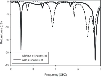
Figure 2 shows the simulation results of antenna with and without the e-shaped slots. Without the slots, the higher return loss is seen at 3.86 GHz and 5.42 GHz. By applying the optimized e-shaped slot, the value of return loss at desired frequency has been decreased to 18.92 dB at 2.45 GHz and -22.39 dB at 5.8 GHz. By adding a slot in the radiating patch, the resonance frequency can be adjusted and at the same time a compact antenna can be obtained.
Frequency (GHZ)
2 3 4 5 6
R
et
u
rn
Los
s
(
dB
)
-25 -20 -15 -10 -5 0
without e-shape slot with e-shape slot
Figure 2: The simulated return loss of antenna with and without e-shaped slot (substrate used: RF-35)
By introducing the gap around the radiating patch, it will affect the value of return loss and frequency. From Figure 3(a), by increasing the gap g1helps to reduce the number of
unwanted return loss at other frequency. While increasing the value of gap g2can improve the value of return loss. From the
parameter study conducted, the best return loss value can be achieved at radiating patch of 15.0 mm x 11.37 mm with substrate size of 70 mm x 50 mm.
Frequency (GHz)
2 3 4 5 6
R
et
u
rn
Los
s
(
dB
)
-30 -25 -20 -15 -10 -5 0
0 mm 10 mm 15 mm
(a)
Frequency (GHz)
2 3 4 5 6
R
et
u
rn
Los
s
(
dB
)
-30 -25 -20 -15 -10 -5 0
8 9 10 11
(b)
Figure 3: The effects of varying the (a) g1and (b) g2for dual-band e-shaped antenna (substrate used: RF-35)
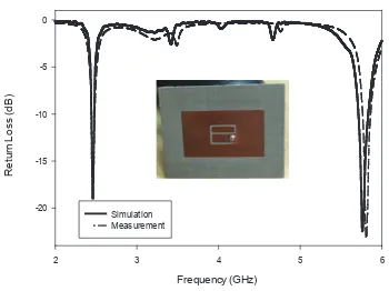
The designed dual-band e-shaped antenna is measured using a vector network analyzer. Figure 4 shows the simulation and measurement return loss of the antenna. The desired operating frequencies are slightly shifted to 2.46 GHz and 5.83 GHz. At low frequency, the simulated return loss is 18.92 dB while the measured return loss is 15.62 dB. At high frequency, the simulated and measured return loss is nearly the same. Based on Table 2, it can be summarized that the measured results are agreed with the simulated results.
L
g2
W
g1
Substrate
W
1W
2L
1Radiating element
Ground Plane
t
e-shaped slot
g2
Dual-Band e-Shaped Antenna for RFID Reader
Figure 4: The simulated and measured return loss of dual-band e-shaped antenna (substrate used: RF-35)
However, the obtained gains are much higher compared to the gain obtained in [7]. This is because the simulated total efficiency of the antenna is high due to the low tangent loss of the RF-35 substrate compared to the tangent loss of the FR4 board.
Table 2:Simulation and measurement results of dual-band e-shaped antenna (substrate used: RF-35)
Simulation Measurement
Frequency (GHz) 2.45 5.8 2.46 5.83
Return Loss (dB) -18.92 -22.39 -15.62 -22.96
Bandwidth (%) 1.80 2.00 1.78 1.70
Gain (dB) 9.74 10.5 7.91 12.63
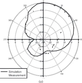
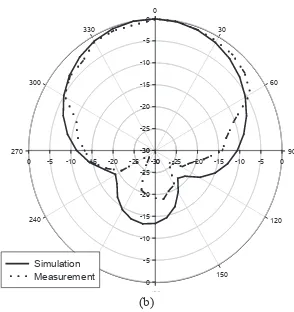
Figure 5 shows the radiation pattern for the e-shaped antenna at lower and upper bands. From Figure 5 (a), the radiation for lower band frequency is said to be directional but at upper frequency (Figure 5 (b)) the radiation is directed at certain angle.
Figure 5: Radiation Pattern for dual-band e-shaped antenna at (a) 2.45 GHz and (b) 5.8 GHz
III.DUAL-BAND E-SHAPED ANTENNA DESIGNED AT0.92GHZ AND2.45 GHZ
Figure 6 shows the simulation of S11 for 0.92 GHz and 2.45 GHz antenna with and without the existence of e-shaped slots. Without the slot, the first and second operating frequencies are seen at 1.7 GHz and 2.5 GHz. By adding the optimized e-shaped slot in the radiating element, the first resonant frequency is reduced to 0.92 GHz and the next operating frequency is obtained at 2.45 GHz. Hence, by adding slot, the current path is lengthened and it can miniature the size of the antenna. With adding slot also can creates other resonances.
Frequency (GHz)
without e-shape slot with e-shape slot
Figure 6: The simulated return loss of antenna with and without e-shaped slots antenna (substrate used: TLC-32)
The simulated return loss for various substrates’ size is shown in Figure 7. Figure 7 shows the effects of varying the gap g1
and g2of the antenna. The frequency shifting can be seen as
the gap is increased. When varying the g2, it gives effect to the
upper frequency. By increasing the g2,the frequency becomes
with the e-shaped slot dimension W1= 30 mm, W2= 28 mm,
Figure 7: Simulation for varying the (a) g1and (b) g2for dual-band e-shaped antenna (substrate used: TLC-32)
Figure 8 shows the simulated and measured return loss of dual-band e-shaped antenna designed using the TLC-32 substrate. The matching properties are good at both 0.92 GHz and 2.45 GHz. However, the measured operating frequencies are shifted to the higher value due to the fabrication and measurement errors.
Figure 8: Simulation and measurement return loss of e-shaped antenna (substrate used: TLC-32)
The simulation and measurement of the antenna are compared as shown in Table 3. The gain of measurement is slightly smaller than the simulated value. However, the antenna is still operates at the desired band.
Table 3: Measurement and Simulation Results of e-shaped antenna (substrate used: TLC-32)
Simulation Measurement
Frequency (GHz) 0.92 2.45 0.93 2.48
Return Loss (dB) -22.98 -20.94 -14.98 -11.48
Bandwidth (%) 1.48 2.47 1.48 2.51
Gain (dB) 6.16 8.93 6.66 7.92
From Figure 9, the radiation pattern shows the directional directivity at both frequency but at 0.92 GHz it directed at 20˚ for maximum lobe.
Dual-Band e-Shaped Antenna for RFID Reader
0
30
60
90
120
150
180 210 240 270
300 330
-30 -25 -20 -15 -10 -5 0
-30 -25 -20 -15 -10 -5 0
-30 -25 -20 -15 -10 -5 0
-30
-25
-20
-15
-10
-5
0
Simulation Measurement
(b)
Figure 9: Radiation Pattern for dual-band e-shaped antenna at (a) 0.92 GHz and (b) 2.45 GHz.
IV. CONCLUSION
In conclusion, by adding slot, it can create other resonances and at the same time can reduce the size of the antenna. This is because theoretically by adding slot it can lengthen the current path. In addition, the Taconic substrate gives relatively the same result for simulation and measurement compared to the FR4 substrate especially when it comes to the higher frequency. By choosing a suitable substrate, it will give high radiation efficiency and will manage to produce the higher gain. This is also because the simulated total efficiency of the antenna is high due to the low tangent loss of the RF-35 substrate compared to the tangent loss of the FR4 board. However, thicker substrate is preferred for 0.92 GHz and 2.45 GHz antenna due to low frequency and bandwidth and constraints. The structure of the dual-band e-shaped antenna proposed in this paper is compact and simple because it applies single feed, single patch and single layer. The
functionability of these antennas is proven as an RFID reader both at the Ultrahigh frequency (UHF) and at microwave frequency (2.45 GHz).
ACKNOWLEDGEMENT
The authors wish to thank the Centre for Research and Innovation Management (CRIM) of Universiti Teknikal Malaysia Melaka (UTeM) for the support of this work under the grant number of PJP/2012/FKEKK (27B) S01030.
REFERENCES
[1] Zhi Ning Chen and Xianming Qing, “Antennas for RFID Application”, Antenna Technology International Workshop (iWAT) 2010, pp. 1-4, 2010.
[2] Suvad Selman, Nesibe Merve Demir and Moamer asanovic, “Dual Band UHF RFID Antenna”, 20th Telecommunication Forum 2012, pp. 1205-1209, Nov 2012.
[3] Chuwong Phongcharoenpanich and Benjaporn Sricharoen, “Dual-Band Circularly Polarized Rectangular Loop Slot Antenna for UHF-RFID Reader”, Wiress Information and Technology 2012, pp. 1-4, 2012.
[4] Ahmed Toaha Mobashsber, Mohamad Tariqul Islam and Norbahiah Misran, “A Novel High-Gain Dual-Band Antenna for RFID Reader Applications”, IEEE Antennas and Wireless Propagation Letters 2010, pp. 653-656, 2010.
[5] C. Phongcharoenpanich and R. Suwalak, “Dual-Band RFID-Reader Antenna using Annular Plate with Curved and Rectangular Slots”, Electromagnetics in Advance Applications 2010, pp.633-636, 2010.
[6] Mursyidul Idzham Sabran, S.K.A. Rahim, and Amuda Yusuf Abdul Rahman, “A Dual-Band Diamond-Shaped Antenna for RFID Application”, Antenna and Wireless Propagation Letters, pp.979-982, 2011.
![Table 1: Frequency range for RFID system [1]](https://thumb-ap.123doks.com/thumbv2/123dok/531630.61527/1.510.52.251.560.602/table-frequency-range-for-rfid-system.webp)