DEVELOPMENT OF DIGITAL FILTER DESIGN TOOL
SULAIMAN BIN HASHIM
This report is submitted in partial fulfillment of requirements for the award of Bachelor of Electronic Engineering (Industrial Electronics) with honours
Fakulti Kejuruteraan Elektronik dan Kejuruteraan Komputer Universiti Teknikal Malaysia Melaka.
UNIVERSTI TEKNIKAL MALAYSIA MELAKA
FAKULTI KEJURUTERAAN ELEKTRONIK DAN KEJURUTERAAN KOMPUTER
BORANG PENGESAHAN STATUS LAPORAN
PROJEK SARJANA MUDA II
Tajuk Projek : DEVELOPMENT OF DIGITAL FILTER DESIGN TOOL Sesi Pengajian : 2008/2009
Saya SULAIMAN BIN HASHIM
mengaku membenarkan laporan Sarjana Muda ini disimpan di Perpustakaan dengan syarat-syarat kegunaan seperti berikut:
1. Laporan adalah hakmilik Universiti Teknikal Malaysia Melaka.
2. Perpustakaan dibenarkan membuat salinan untuk tujuan pengajian sahaja.
3. Perpustakaan dibenarkan membuat salinan laporan ini sebagai bahan pertukaran antara institusi pengajian tinggi.
4. Sila tandakan ( √ ) :
SULIT* (Mengandungi maklumat yang berdarjah keselamatan atau kepentingan Malaysia seperti yang termaktub di dalam AKTA RAHSIA RASMI1972)
TERHAD* (Mengandungi maklumat terhad yang telah ditentukan oleh organisasi/badan di mana penyelidikan dijalankan)
TIDAK TERHAD
Disahkan oleh:
__________________________ ___________________________________
(TANDATANGAN PENULIS) (COP DAN TANDATANGAN PENYELIA)
Alamat Tetap: 121, JALAN INTAN,
GOMBAK SETIA,
53100 KUALA LUMPUR,
WILAYAH PERSEKUTUAN..
Tarikh: 27 APRIL 2009 Tarikh: 27 APRIL 2009
*CATATAN : Jika laporan ini SULIT atau TERHAD, sila lampirkan surat daripada pihak berkuasa/organisasi berkenaan
dengan menyatakan sekali tempoh laporan ini perlu dikelaskan sebagai SULIT atau TERHAD.
iii
“I hereby declare that this report is the result of my own work except for quotes as cited in the references.”
Signature : ………...
iv
“I hereby declare that I have read this report and in my opinion this report is sufficient in terms of scope and quality for the award of Bachelor of Electronic
Engineering (Industrial Electronic) with honours.”
Signature : ………
Supervisor’s Name : AZAHARI BIN SALLEH
v
ACKNOWLEDGEMENT
First of all, I would like to thank my project advisor, Mr. Azahari bin Salleh, for his helpful support and guidance to accomplish this thesis. Credit also goes to Mr. Nik Mohd Zarifie bin Hashim and Mr. Abd Shukur bin Jaafar for observing and judging my presentation of the project as the panel during the seminar. Besides, I also would like to bestow gratitude to my families who have been supporting me in term of costs and facilities for completing this project. As well, praise to all my course-mates for never-ending support, motivation and ideas.
Finally, I would like to give merit to housemate and all of my friends of 4 BENE who have directly or indirectly contributed and spent their precious time in helping me to accomplish this project.
vi
ABSTRACT
vii
ABSTRAK
Matlamat utama projek ini ialah mencipta sebuah alat untuk mereka yang berasaskan interaksi pengguna grafik (GUI) yang juga salah satu dalam MATLAB. Disebabkan skop teramat luas, hanya
(IIR) yang ditumpukan dalam projek ini. Setelah filter IIR dikaji dan diteliti, alat pereka yang dibangunkan ini terdiri daripada tiga jenis iaitu Butterworth, Chebyshev, dan Elliptic. Setiap satu daripada tersebut
mempunyai tiga jenis iaitu dan . Alat pereka
ini akan beroperasi dalam dua buah yang pertama dikenali
sebagai dan yang kedua pula adalah .
hanya digunakan untuk memilih yang hendak direka bersama dengan jenis respon yang hendak digunakan dan selepas dipilih, proses mereka filter dijalankan di . Selepas perekaan dan pengiraan,
viii
TABLE OF CONTENT
CHAPTER TITLE PAGE
PROJECT TITLE i
ACKNOWLEDGEMENT v
ABSTRACT vi
ABSTRAK vii
TABLE OF CONTENT viii
LIST OF TABLE xi
LIST OF FIGURE xii
LIST OF ABBREVIATIONS xiv
LIST OF APPENDIXES xv
I INTRODUCTION 1
1.1 Project Background 1
1.2 Objectives 2
1.3 Problem Statement 3
1.4 Scope 3
1.5 Thesis Outline 4
II DIGITAL FILTER 5
2.1 Digital Filter Concept 5
ix
III METHODOLOGY 21
3.1 Project Flow 21
3.1.1 General Flow Chart 22
3.2 Laying Out the Interface 24
3.2.1 System Flowchart 25
3.3 Programming 27
3.3.1 Programming Flow Chart (Menu window) 28 3.3.2 Programming Flow Chart (Design window) 31
IV RESULT AND ANALYSIS 33
4.1 Result 33
4.2 Output 34
4.2.1 Menu window 34
4.2.2 Design window 35
x
V CONCLUSION AND SUGGESTION
5.1 Conclusion 42
5.2 Problems 43
5.3 Suggestions 44
REFERENCES 45
xi
LIST OF TABLES
NO DESCRIPTION PAGE
2.1 GUI Design Technique 15
xii
LIST OF FIGURES
NO TITLE PAGE
2.1 Cascaded Filter Stages 8
2.2 Direct form equation representation 9
2.3 Direct form equation II representation 9
2.4 The bode plot for first order Butterworth Filter 10 2.5 The frequency response for Chebyshev Filter 11 2.6 The frequency response for Elliptic filter 12
2.7 Example of simple GUI 14
2.8 GUIDE Tools in MATLAB 12
3.1 Whole methodology of the project 24
3.2 Layout Editor 25
3.3 Flow Chart of the System 26
3.4 Menu window programming flow 29
3.5 Design window programming flow 31
4.1 Digital Filter Design Tool (Menu window) 33
xiii
4.10 Example of Elliptic Low-pass Filter design 39 4.11 Example of Elliptic Band-pass Filter design 39
xiv
LIST OF ABBREVIATIONS
DSP Digital Signal Processing DFD Digital Filter Design FIR Finite Impulse Response IIR Infinite Impulse Response GUI Graphical User Interface GUIDE GUI Design Environment MATLAB Matrix Laboratory
Fs Sampling Frequency
Fpass/Fpb End of the passband frequency Fstop/Fsb Beginning of the stopband frequency Apass/Rpb Passband ripple
xv
LIST OF APPENDIXES
NO TITLES PAGES
1 APPENDIX A
“M-file Algorithm for Menu Window”
46
2 APPENDIX B
“M-file Algorithm for Butterworth Highpass Filter”
49
3 APPENDIX C
“M-file Algorithm for Butterworth Lowpass Filter”
52
4 APPENDIX D
“M-file Algorithm for Butterworth Bandpass Filter”
56
5 APPENDIX E
“M-file Algorithm for Chebyshev Type I Highpass Filter”
60
6 APPENDIX F
“M-file Algorithm for Chebyshev Type I Lowpass Filter”
63
7 APPENDIX G
“M-file Algorithm for Chebyshev Type I Bandpass Filter”
xvi
8 APPENDIX H
“M-file Algorithm for Elliptic Highpass Filter”
70
9 APPENDIX I
“M-file Algorithm for Elliptic Lowpass Filter”
74
10 APPENDIX J
“M-file Algorithm for Elliptic Bandpass Filter”
CHAPTER I
INTRODUCTION
1.1 Project Background
Electronic filters have a relevant importance in electronic systems because they are present in almost any electronic system. For example, communication systems, as many other electric systems, make intensive use of filtering to separate unwanted noise from the desired signal. Analog filter design is one of the most important areas of electronic design. Although some analog filter design books include simple, well-tested filter designs, filter design is often reserved for specialists because it requires advanced mathematical knowledge and understanding of the processes involved in the system affecting the filter. Modern sampling and digital signal processing tools enable you to replace analog filters with digital filters in applications requiring flexibility and programmability. These applications include audio, telecommunications, geophysics, and medical monitoring.
2
computational task requiring a significant amount of numerical calculations to obtain either the parameters of a filter transfer function or the element values for a filter circuit realization
The main idea of this project is to design an easy configuration for the filter courses as tool for teaching aid using the Graphical User Interface (GUI) in MATLAB Software. The advantage of the filter design software package is it makes use of one of the MATLAB toolboxes, the signal toolbox but use with an interface that makes possible for a beginner to readily design a filter. So, in this project, the initial task is choose a type of filter as a prototype for this project and as a result, digital filter design was chosen as the primary study of the project.
1.2 Objectives
To accomplish a project, the objective of the project must be cleared and can be understand to achieve. Hence, the objective of this project is:
§ To implement an GUI-based digital filter design tool
§ To provide a tool to be used in teaching aid besides to assist the novice user in digital filter design course.
3
1.3 Problem statement
Filter design is an intensive computational task requiring a significant amount of numeral calculation to obtain either the parameters of a filter transfer function or element values for a filter circuit realization which is really hard for education progress. The cost of available filter design software is normally very high.
Therefore, the main idea of this project is to design an easy configuration for the filter courses as tool for teaching aid using the Graphical User Interface (GUI) in MATLAB Software. This tool will be helpful and encourage the novices to further explore the filter design courses because of its user friendly.
1.4 Scope
The project is focus on developing the tool for designing digital filter. The main tool use in this project is the MATLAB Software.
• The project is focusing on IIR digital filter design that consist of: – Butterworth Filter
– Chebyshev Type I Filter – Elliptic Filter
• Each filter above has three responses implemented: – Lowpass
– Highpass – Bandpass
• Every filter evaluated will display four graph response: – Magnitude Response
4
– Impulse Response – Pole/Zero Plot
• The implementation of filter design toolkit is heavily involved GUI tool in MATLAB software.
The result of this project will be shown in simulation where GUI tool in MATLAB are use as an interface for the filter design. The target of this project is to encourage the students or novice users to design a filter in short period of time without having any knowledge about programming in MATLAB. The project will be focus on digital filter design.
1.5 Thesis Outline
CHAPTER II
DIGITAL FILTER
This chapter explains the necessary background information to understand the research presented in this report. The first part of this chapter will introduce some of the fundamental ideas involved in the design and development of this project. It will also include the current knowledge relating to Digital Filter, GUI, and MATLAB.
2.1 Digital Filter Concept
In electronics, a digital filter is any electronic filter that works by performing digital mathematical operations on an intermediate form of a signal. This is in contrast to older analog filters which work entirely in the analog realm and must rely on physical networks of electronic components to achieve the desired filtering effect.
6
2.1.1 Types of digital filters
Many digital filters are based on the Fast Fourier transform, a mathematical algorithm that quickly extracts the frequency spectrum of a signal, allowing the spectrum to be manipulated (such as to create pass-band filters) before converting the modified spectrum back into a time-series signal.
The transfer function for a typical linear digital filter can be expressed as a
behaviour, but if the denominator is unity, then this is the form for a
2.2 Infinite Impulse Response Filters (IIR)
The digital filters designed using the DFD applications are either Infinite Impulse Response (IIR) or Finite Impulse Response (FIR) filters. IIR filters process both input and output samples. This allows IIR filters to have very sharp transitions in their frequency response characteristics, which is very useful in many applications. The nonlinear phase distortion associated with IIR filters sometimes can limit their selection in many phase sensitive systems.
7
coefficients ( &). In most IIR filter designs, coefficient 0 is 1. The output sample at the present sample index consists of the sum of scaled present and past inputs (( and ( %
when % 0) and scaled past outputs (' &). The response of the general IIR filter to an impulse ((0 = 1 and ( = 0 for all 0) is called the impulse response of the filter. The impulse response of the filter described by equation (2-2) is indeed of infinite length for nonzero coefficients. In practical filter applications, however, the impulse response of stable IIR filters decays to near zero in a finite number of samples.
The advantage of digital IIR filters over finite impulse response (FIR) filters is that IIR filters usually require fewer coefficients to perform similar filtering operations. Thus, IIR filters execute much faster and do not require extra memory, because they execute in place. The disadvantage of IIR filters is that the phase response is nonlinear. If the application does not require phase information, such as simple signal monitoring, IIR filters may be appropriate. You should use FIR filters for those applications requiring linear phase responses. IIR filters are also known as recursive filters or autoregressive moving-average (ARMA) filters.
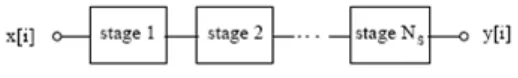
2.2.1 Cascade Form IIR Filtering
8
filter stages. The direct form transfer function of the filter given by equation 2-2 (with 0 = 1) can be written as a ratio of "transforms, as follows:
By factoring equation 2-3 into second-order sections, the filter's transfer function becomes a product of second-order filter functions
∏
This new filter structure can be described as a * * of second-order filters.
Figure 2.1: Cascaded Filter Stages
Each individual second-order stage can be implemented using the direct form filter equations: