MODELING OF A GANTRY CRANE USING ON-OFF MOTOR
IMPLEMENTATION
SITI RADHIAH BINTI JUMALI
This report is submitted in partial fulfillment of the requirement for the award of Bachelor of Electronic Engineering (Industrial Electronics) With Honours
Faculty of Electronic and Computer Engineering
Universiti Teknikal Malaysia Melaka
UNIVERSTI TEKNIKAL MALAYSIA MELAKA
FAKULTI KEJURUTERAAN ELEKTRONIK DAN KEJURUTERAAN KOMPUTER
BORANG PENGESAHAN STATUS LAPORAN
PROJEK SARJANA MUDA II
Tajuk Projek : MODELING OF A GANTRY CRANE USING ON-OFF MOTOR IMPLEMENTATION
Sesi
Pengajian : 2/2008/2009
Saya SITI RADHIAH BINTI JUMALI
mengaku membenarkan Laporan Projek Sarjana Muda ini disimpan di Perpustakaan dengan syarat-syarat kegunaan seperti berikut:
1. Laporan adalah hakmilik Universiti Teknikal Malaysia Melaka.
2. Perpustakaan dibenarkan membuat salinan untuk tujuan pengajian sahaja.
3. Perpustakaan dibenarkan membuat salinan laporan ini sebagai bahan pertukaran antara institusi pengajian tinggi.
4. Sila tandakan ( √ ) :
SULIT*
(Mengandungi maklumat yang berdarjah keselamatan atau kepentingan Malaysia seperti yang termaktub di dalam AKTA RAHSIA RASMI 1972)
TERHAD* (Mengandungi maklumat terhad yang telah ditentukan oleh organisasi/badan di mana penyelidikan dijalankan)
TIDAK TERHAD
Disahkan oleh:
__________________________ ___________________________________
“I hereby declared that this report entitle Modeling of a Gantry Crane Using On-Off
Motor Implementation is a result of my own work except for the works that have been
cited clearly in the references.”
Signature : ……….
Student Name : SITI RADHIAH BINTI JUMALI
“I hereby declared that I have read this report in my opinion this report is sufficient in
terms of the scope and quality for the award the Bachelor of Electronic Engineering
(Industrial Electronics) With Honours.”
Signature : ……….
Supervisor’s Name : PN AZDIANA BINTI MD. YUSOP
Special dedicated to my beloved parents, family, teacher and fellow friends, who had
ACKNOWLEDGEMENT
First of all, I would like to thank my supervisor, Pn. Azdiana Binti Md. Yusop
for all the information, knowledge and guidance throughout this project and also her
patience and dedication. Secondly, I would like to thank all the people that have been
involved directly and indirectly throughout the progression of this project. I also
would like to thank to all my friends for their help and also information. Last but not
ABSTRACT
Crane payloads frequently swing with large amplitude motion that degrades
safety and throughput. Open-loop methods have addressed this problem, and has
proven effective on crane but just for reducing the sway during and after move.
Closed-loop methods have also been used, but generally require the speed of the
driving motors to be precisely controlled. This paper develops a feedback control
method for controlling motors to cancel the measured payload oscillations by
intelligently timing the ensuing on and off motor commands. To generate the on-off
motor command the measurement using payload oscillation cancellation and vector
input shaper calculation need to be used. The on-off motor command is design to
control the trolley movement without vibration and reduce the swing angle of the
ABSTRAK
Beban kren yang selalunya berayun dengan amplitud pergerakan yang besar
akan mengurangkan tahap keselamatan dan nilai keluaran. Kaedah gelung terbuka
telah menyelesaikan masalah ini dan telah dibuktikan berkesan tetapi hanya untuk
mengurangkan hayunan pada beban semasa dan selepas pergerakan. Kaedah gelung
tertutup juga telah digunakan untuk menyelesaikan masalah ini, tetapi secara
keseluruhannya memerlukan ketepatan dalam mengawal kelajuan motor tersebut. Di
dalam projek ini, kaedah suapan balik digunakan untuk mengawal motor untuk
menghapuskan talaan beban oleh kadar masa yang tepat untuk menentukan arahan
“on” dan “off” motor. Arahan “on-off motor” dihasilkan berpandukan kiraan ukuran
sudut ayunan beban dan vektor bentuk masukan. Arahan “on-off motor” direka adalah
untuk mengawal pergerakan troli tanpa gegaran dan mengurangkan sudut hayunan
TABLE OF CONTENTS
CHAPTER ITEM PAGE
PROJECT TITLE i
DECLARATION FORM OF REPORT STATUS ii
DECLARATION iii
SUPERVISOR’S DECLARATION iv
DEDICATION v
ACKNOWLEDGEMENT vi
ABSTRACT vii
ABSTRAK viii
TABLE OF CONTENT xi
LIST OF TABLES xiii
LIST OF FIGURES xiv
I INTRODUCTION
1.1 Project Introduction 1
1.2 Project Objectives 2
1.3 Problem Statement 3
1.4 Scope Project 3
1.5 Methodology 4
1.6 Thesis Outlines 6
II LITERATURE REVIEW 7
2.1 Control System
2.1.1 On-off Motor Control 9
2.1.2 Feedback Control 10
2.1.3 PID Control 11
2.2 Non-Linear Control
2.2.1 Properties of Non-Linear System 12
III MODELLING A GANTRY CRANE
3.1 Introduction 13
3.2 Equation of Motion for Trolley 14
3.3 Concept of Sensorless Anti-
Swing Control 16
3.4 Vector Based Input Shaper Calculation 18
IV HARDWARE IMPLEMENTATION
4.1 Introduction 25
4.2 Hardware Requirement
4.2.1 Gantry Crane 26
4.2.2 DAQCard-700 27
4.2.3 BNC-2110 28
4.3 Electrical Components
4.3.1 Stepper Motor 29
V RESULTS AND ANALYSIS
5.1 Simulation
5.1.1 MATLAB and Simulink 32
5.1.2 Stateflow 33
5.1.3 Simulation Results 33
5.2 Analysis
5.2.1 Simulation Analysis 37
5.2.2 Swing Angle Analysis 38
5.3 Interfacing of the Block Design
5.3.1 x-PC Target 39
VI CONCLUSION AND FUTURE WORK
6.1 Conclusion 42
6.2 Future Work 43
REFERENCE 44
LIST OF TABLE
NO. TITLE PAGE
4.1 Specification of the Gantry Crane 26
4.2 The Digital Logic Levels 28
LIST OF FIGURES
NO. TITLE PAGE
1.1 The Gantry Crane 1
1.2 Block Diagram of Methodology 5
2.1 Input Shaping a Step Input 9
2.2 Feedback Block 10
2.3 A Block Diagram of PID Controller 11
3.1 Model of Gentry Crane 14
3.2 Sensorless Anti-swing Control 16
3.3 Impulse Sequence 18
3.4 Vector Diagram 18
3.5 Summing the 3 vector and get zero vibration 19
3.6 Vector represent for turning the motor on 20
3.7 Vector Diagram for Calculate time to turn motor off 21
3.8 Angle used to calculate command initiation time 22
4.1 Drawing Sketch of the Crane 26
4.2 The Trolley 27
4.3 The Connection of BNC with the Personal Computer 28
4.4 The Stepper Motor 29
5.1 The Function Block Parameter 33
5.2 The Stateflow Chart 34
5.3 The Discrete PID controller Parameter on Block Parameter 35
5.4 Position of the Trolley at Position Output 35
5.5 Swig Angle at Radian Output 36
5.6 Nonlinear Model Parameter 36
5.7 Settling Time for Position Graph 38
5.8 The xPC Target Entering 40
LIST OF APPENDICES
NO. TITLE PAGE
APPENDIX A HARDWARE 46
APPENDIX B A FEEDBACK CONTROL SYSTEM FOR
SUPPRESSING CRANE OSCILLATIONS
WITH ON-OFF MOTOR 47
CHAPTER I
INTRODUCTION
1.1 Project Introduction
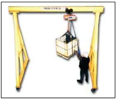
A gantry crane is a type of overhead crane. With a gantry crane, the supports
holding the crane up are fixed in location. They cannot move, and therefore the crane
cannot move. For this reason, everything that the crane is going to lift must be
brought to the crane. The supports form a large rectangular frame upon which the
crane can move forward and back, and left and right. Anything that can be reached by
[image:17.612.238.441.540.711.2]the gantry crane is referred to as being in its operating area.
Gantry cranes are very common in factories, where they are used to move
things along the factory floor as the product is slowly assembled. For instance, if one
is building a large metal piece of equipment, the metal parts may arrive on a truck.
The truck will park within the operating area of the gantry crane, and the gantry crane
can then be used to unload the parts. The gantry crane may also be used to move the
parts around, typically along the assembly line as the components are assembled.
From the privious project, the gantry crane is controlled by the PIC
programming, that is programmed by the time and speed of the motor. In this situation
the swing angle of the object can not be controlled.
The fundamental motions of a gantry crane consist of traversing, load hosting
and load lowering [1]. When the crane is starting to move or the crane is stopping, it
induces undesirable swinging of the suspended load. This swinging can caused
damage to the payload or other objects in the workplace. Traditionally, an
experienced crane operator is required to keep the oscillations under control. But, the
operator should be expertise to control the crane. It is because that the payload is free
to swing in a pendulum like motion.
There are many types of the approach that can be used to implement in gantry
crane. Some of the approaches are open-loop and close-loop. The open-loop approach
is the input shaping where input shaping is a feedforward control technique for
improving the settling time and the positioning accuracy, while minimizing residual
vibration, of computer-controlled machines. Moreover the close-loop approach needs
the feedback controller to do the correction on the system.
1.2 Project Objectives
The objective of this project is to design the gantry crane system with
feedback control method that will drive the system from initial position into a target
1.3 Problem Statement
Now in our industrial factory, there are so many accidents that involve the
workers. One of the accidents is when the workers want to transport the heavy object
in a workspace using the forklift. The forklift needs someone to drive it and control in
their entire angle such back, front and around it. To reduce the accident in this
situation, this gantry crane project are come out to solve the problem, but there are
some problem with cranes is that the payload can swing freely. These oscillations
pose safety hazards and can damage the payload and other objects in the workplace.
Crane travel and transverse motion especially when starting or stopping, induce
undesirable swinging on the suspended load. This swinging could cause the
suspension rope to leave its groove which could lead to overwrapping and possibly
serious accident. So there are some commands (on-off motor) that can control the
oscillations and make it safe.
1.4 Scopes of Project
Firstly, do some researches about a gantry crane system with a feedback
control system for suppressing crane oscillations with on-off motors. After that,
feasibility study and read up related technical knowledge such as:
a) non-linear feedback
b) on-off control
Then find the correct calculation to control the system of the motor. In this
part, the calculation must be correct so that the control block can functioned correctly.
For the simulation part:
a) Derive the function to control the on-off motor.
b) Simulate by using the stateflow chart to control the motor by the angle of
the swing.
c) Implement the block function by using the close-loop system.
d) Develop the mathematical modeling to control the on-off function by using
1.5 Methodology
In order to meet the objective of the project, the design of the system is consist
of several stages. In the subsequent sections, each subsystem will be discussed in
terms of criteria, calculations and selection of the project specifications. The
following methods will be followed closely:
a) The initial stage of the project is basely solely on research about the basic
concept of gantry crane whereby data and information are obtained
through various medium, such as internet, books, journal, proceeding
paper, broachers and more.
b) After the research about gantry crane had been done, research about on-off
commands will be done. The research is about how to generate on-off
commands and apply it to the gantry crane system.
c) Then the appropriate design circuit was find to implement the circuit.
d) After finding the appropriate circuit, the implementation of the
mathematical function on the MATLAB is done in order to ensure that the
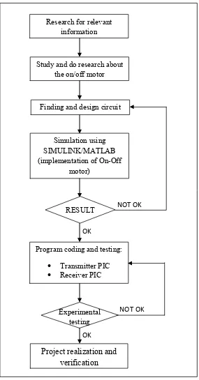
Figure 1.2 Block Diagram of Methodology
Research for relevant information
Study and do research about the on/off motor
Finding and design circuit
Simulation using SIMULINK/MATLAB (implementation of On-Off
motor)
Program coding and testing: • Transmitter PIC • Receiver PIC
RESULT
Experimental testing
Project realization and verification
NOT OK
NOT OK OK
1.6 Thesis Outlines
This thesis is represented by seven chapters to describe the methodology of the
project and the outline of the feedback control system for suppressing the crane
oscillations with on-off motor implementation on the gantry crane.
Chapter I discuss the overview of the project in introduction, objectives,
problem statement, scope of the project and methodology.
Chapter II explanation about the research and information regarding the
facts from journal, books and other references. The literature reviews also are
included in this chapter.
Chapter III describes the process of the project where the calculation and
the research of the gantry crane are included.
Chapter IV elaborate about the devices that play the important role in this
project and illustrates about the gantry crane model. This chapter also includes the
hardware and software development and their methodology.
Chapter V explain about hardware implementation. This chapter consists
of the information about the gantry crane model specification including the
equipments, circuit and gantry specifications.
Chapter VI discuss the project finding base on the interfacing between the
software and the hardware and the results of the project.
Chapter VII consist the conclusion of the project and the future
CHAPTER II
LITERATURE REVIEW
This chapter discuss the reference that had been used in term to get more
information about gantry crane including the controller, requirement needed, and the
characteristics of the gantry crane. This information is to ensure this project will
achieve its objectives.
Cranes are frequently used to transport heavy objects in a cluttered workspace.
One inherent problem with cranes is that the payload can swing freely. These
oscillations pose safety hazards and can damage the payload or other objects in the
workplace. Traditionally, an experienced crane operator is required to keep the
oscillations under control. More recently, various control approaches have been
applied to augment the operator’s skill. These approaches fall into open and
closed-loop categories [1].
Open-loop approach is optimal control, which calculates a motion trajectory
off line based on the mathematical model of the system but if the model is inaccurate,
the performance will undergo. This is also the case with input shaping, but to a lesser
To increase the ability of the controller the feedback control are need to be
added. This feedback control is in the close-loop system that needs to control the
velocity of the trolley and the swing angle of the cable to reduce the payload
oscillation [1]. Most of automatic gantry crane controls proposed by researchers use
two controllers for controlling both trolley position and swing of the crane payload. It
is position controller and swing controller [2].
In other method of the feedback control is from conventional PID
(proportional-integral-derivative) to intelligent the approaches [2]. Omar [3] proposed
PD controls for both trolley position and swing suppression. Even PID controller is
commonly used; they are not always used in the best way because the controller is
often poorly tuned. It is quite common that derivative action is not used. The reason is
that it is difficult to tuned three parameter by trial and error. A block diagram of PID
controller in a closed-loop system.
From Park and Chang in “Vibration control of a telescopic handler using time
delay control and commandless input shaping technique” another method to reduce
the effect of disturbance on a vibration system is ‘commendless’ input shaping for a
telescopic handler. They introduce a pulse that induces vibration equal in magnitude
but opposite in phase of the vibration caused by unloading. They show the method’s
potential by using it to reduce vibration by about 75%. However, issues of properly
timing the pulse and ease of calibration appear to be challenging [4].
By Neil Singer [6] an input shaping is easier to derive and implement than
time-optimal control schemes and does not require the feedback mechanisms of
closed-loop and adaptive controllers. Rather than attempt to obtain exactly zero
residual vibration (which is impossible on real machines), the version of Input
Shaping described here yields non-zero, but low levels of sway. Input Shaping is
implemented in real time by convolving the command signal with an impulse
sequence (an input shaper). This process is illustrated in figure 2.1 with a step input
and an input shaper containing three positive impulses. Note that the shaped input that
results from the convolution has a rise time which is longer than the unshaped input
by an amount equal to the duration of the input shaper. Similarly, the deceleration