UNIVERSITI TEKNIKAL MALAYSIA MELAKA
DESIGN AND ANALYSIS OF INTELLIGENT MULTIPLE
GANTRIES SYSTEM
This report submitted in accordance with requirement of the Universiti Teknikal Malaysia Melaka (UTeM) for the Bachelor Degree of Manufacturing Engineering
(Robotic and Automation) with Honours.
by
MUHAMMAD IZZAT BIN HJ. RAMLAN ROSS
UNIVERSITI TEKNIKAL MALAYSIA MELAKA
BORANG PENGESAHAN STATUS LAPORAN PROJEK SARJANA MUDA
TAJUK: Intelligent Multiple Gantries System
SESI PENGAJIAN: 2009/10 Semester 2
Saya MUHAMMAD IZZAT BIN RAMLAN ROSS
mengaku membenarkan Laporan PSM ini disimpan di Perpustakaan Universiti Teknikal Malaysia Melaka (UTeM) dengan syarat-syarat kegunaan seperti berikut:
1. Laporan PSM adalah hak milik Universiti Teknikal Malaysia Melaka dan penulis. 2. Perpustakaan Universiti Teknikal Malaysia Melaka dibenarkan membuat salinan
untuk tujuan pengajian sahaja dengan izin penulis.
3. Perpustakaan dibenarkan membuat salinan laporan PSM ini sebagai bahan pertukaran antara institusi pengajian tinggi.
DESIGN AND ANALYSIS OF INTELLIGENT MULTIPLE
GANTRIES SYSTEM
MUHAMMAD IZZAT BIN RAMLAN ROSS
DECLARATION
I hereby declare that this report entitled “Intelligent Multiple Gantries System” is the result of my own research except as cited in the references.
Signature :
Author’s Name : Muhammad Izzat Bin Ramlan Ross
APPROVAL
This report is submitted to the Faculty of Manufacturing Engineering of UTeM as a partial fulfillment of the requirements for the degree of Bachelor of Manufacturing Engineering (Robotic and Automation). The members of the supervisory committee are as follow:
(Main Supervisor)
i
ABSTRACT
ii
ABSTRAK
iii
DEDICATION
Specially dedicated to
my beloved parents who have encouraged, guided and inspired me
iv
ACKNOWLEDGEMENTS
I will take this opportunity to express my gratitude to all people who have helped me in completing this report. Firstly, I would like to thank my project supervisor, Mr. Hisham Bin Nordin for providing lots of help to guide me to complete this report. With his teachings that have been giving me opportunity to carry out my research about the intelligent multiple gantry system. Not to mention the amount of time spend by him to meet and discuss about the details of my project.
Next, I also want to thank my family, especially my parents for giving me support to do the research for the project. Without their help, it will be difficult to achieve what should be done to get the necessary information about this project. Besides that, my friends also have gladly helped me especially in how to make the good project report. With the reference from the senior I have been able to know the criteria that should be included in the report.
vi
3.6 Prototype programming & interfacing 31
3.7 Testing and analysis
3.8 Block diagram of the system 32
3.9 Operation flowchart of the system 33
vii
viii
REFERENCES 74
ix
LIST OF FIGURES
Figure 1.1 A simple sketch of intelligent multiple gantry system workplace 5
Figure 2.1 Tightly Coupled Serial Production System 17 Figure 2.2 Schedule S1 Figure 3.1 Methodology Flow Chart 24
Figure 3.2 Motor actuators 28
Figure 4.6 The aluminium railing tracks 39 Figure 4.7 The mechanical structure of intelligent multiple gantry system Figure 4.8 Testing the motor using battery 40
x
Figure 4.10 Electronic circuit of the system 41
Figure 4.11 The pin outs of DB25 connector
Figure 4.12 Fuzzy1 functions 43
Figure 4.13 Fuzzy2 functions 44
Figure 4.14 Inputs for the functions
Figure 4.15 Outputs for the functions 45
Figure 4.16 Rules editor (1 – 11)
Figure 4.17 Rules editor (rule 12 – 20) 46
xi
LIST OF TABLES
Table 3.1 Gantt chart for the project 25
Table 4.1 Parts description for wheeled motor hanger 36 Table 4.2 List of components for electronic circuit development 41
Table 4.3 Icons used in the Simulink workspace 48
Table 4.4 Settings for the Simulink icons 49
Table 4.5 Specifications of the mechanical structure 51
Table 5.1 Mapping of the gantry movements 68
xii
LIST OF ABBREVIATIONS, SYMBOLS,
NOMENCLATURES
AC - Alternating current
EOT - Electrical Overhead Travelling AI - Artificial Intelligence
LIFE - Laboratory for International Fuzzy Engineering CCD - charge-coupled device
CPU - Central Processing Unit MCU - Microcontroller Unit
1
CHAPTER 1
INTRODUCTION
1.1 Background
Gantry systems can be widely used for a range of applications, from assembly and electronic manufacturing, to vision systems and industrial automation. In semiconductor assembly and packaging, positioning systems using gantries are useful where a work space spans a predefined area and it is necessary to position a device accurately at various positions within the area.
Travel distance, speed, acceleration, accuracy of placement and reliability are relevant factors for consideration in the design of gantry systems. Accuracy of placement and repeatability are especially critical for demanding applications where a tool or device must be positioned accurately with only a small margin for error. Conventionally, gantry systems utilized ball screw-based mechanisms and AC servomotors for driving the gantry. However, ball screws have inherent drawbacks such as relatively slow speed and lower precision.
A gantry is defined as a frame on which barrels can be set horizontally. While a gantry is define as:
a) A framework that spans a distance, often moving on wheels at each end, used for carrying a traveling crane
2
c) A wheeled framework with a crane, platforms at different levels, etc., used for assembling, positioning, and servicing a large rocket at its launching site.
Basically, a gantry system is used to transfer big and heavy load or parts from a place to another. Usually, this machine is use in factories and other industrial sites. Its size is big because in the industrial sites, it is important for the gantry crane to be able to pick a large amount of load in order to save time and cost for the transfer work to be done.
The purpose for this project is to find the way to create a model of gantry system that can transfer the payload more than one round in a certain time. Furthermore, the system should be able to think and make decisions simultaneously on how to pick and transfer a load when there will be obstacles that hinder the gantry system movements.
The intelligent system that can control the decision of the gantry crane will be design as a microcontroller. It is because using the microcontroller, the cost of burning the chip from the program is affordable and not very complicated. Besides that it is to build the program of the gantry system using the microcontroller software.
1.2 Problem Statement
3 1.3 Objectives
The objectives of this project are:
a) To develop a mini-sized model of an intelligent multiple gantry system.
b) To implement an intelligent system into the model so that it can operate according the rules created.
1.4 Scope
In this project, the scope will be covered in the topics such as:
a) Programming the controller. By using the Matlab software, the sets of rule will be create in order for the gantry system to display its operations.
b) Construction of the gantry system model. The design will be according the choices from the design layout that will be drawn, with its dimensions.
c) Interfacing of the program to the model. The programming can be apply to the system after the interfacing is been done to the controller.
4
problems. It is hope by designing such intelligence that can help in such operations, the manufacturing industries will gain benefits from the proposal of this project.
1.5.2 Project description
The intelligent multiple gantries system is a project that is build for the purpose to implement the intelligence in the gantry system so that it can do multi task operations based on the programming that has been design using fuzzy logic controller. Besides that, this project also aims to show that using a mini model of the gantry system, a simple programming can be executed using the rule develop based on the distance of the gantry crane from the workplaces involve and the priorities set by the controller.
The basic implementation of artificial intelligence will be essential in developing the intelligent multiple gantry system. In order to create a simple but effective rule so that the system will do its operations as desired, the rules regarding the movements of the gantry must be created. First and foremost, the rules must apply the concepts that the gantry must be able to process and make specific decisions when facing incoming or unknown obstacles. The consideration of the rule for the multiple gantry system operations must be based on the distance of the gantry from its programmed destination and the priorities of the operations. Some scheduling example that have been analyzed are also been used as a reference of the concept of how the gantry system will operate according what is programmed by the microcontroller.
5
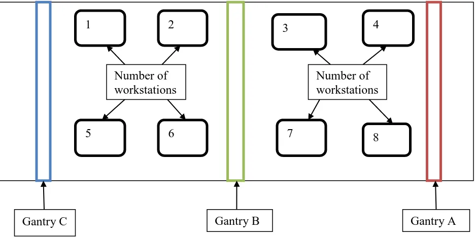
Figure 1.1: A simple sketch of intelligent multiple gantry system workplace
From the sketch, we can identify there are three sets of gantries, which is identified as Gantry A, Gantry B and Gantry C. The different colors are used to identify all three of gantries. Then, in the workplace there will be at least 8 different workstations for the loads to be place. The denoted numbers in the rectangular boxes shows the number of the workstations where the load will be transferred according to its desired place according to the program being executed by the microcontroller. meet at the same path during some intervals is high. Besides that, each of the gantries will
6
be given its own travelling area that covers the transfers of the load at the workplace which situated near the areas that the gantries position. For the area covers, it is set that:
a) Gantry A will cover the transferring of loads at workplaces number 3, number 4, number 7 and number 8;
b) Gantry B will cover the transferring of loads at workplaces number 2, number 3, number 6 and number 7; and
c) Gantry C will cover the transferring of loads at workplaces number 1, number 2, number 5 and number 6.
The reason for the setting of each set of gantries with its own covering area is to make the basic transferring of loads more easy. Moreover, it is productive and save time as all the three sets of gantries will be able to perform its tasks in its own areas, providing that no complicated rule come up from the controller.
During some cycle of operations, some difficulties may occur of the gantries to move. For example, the rules of operations may come up such as the commands above:
a) The gantry A wants to transfer a load to the workplace number 6. But, at the same time the gantry B also wants to transfer a load to workplace number 8.
b) The gantry B wants to transfer a load to workplace number 5. At the same time, the gantry C also wants to transfer a load to workplace number 7.
c) Both of gantry A and gantry C wants to transfer a load at workplace number 5 and number 8 respectively.
7
The criteria to design a rule that obeys the operation flow must be based on the initial and final positions of the gantry system during a cycle of operations. Besides that, the positions of the gantries must also influence the decision making of the output results. It means that the output will be determined based on the distance of the gantries from its respective positions. For example:
a) If the gantry A is assign to transfer a load to workplace number 6 while the gantry B also at the same time is assign to transfer a load to workplace number 7, a priority rule based on the comparative distance between both gantry and its respective destinations will be design so that the gantry B will move first because the distance between it and the workplace is shorter than the distance of the gantry A and its destination.
b) The gantry C wants to transfer a load to workstation number 6 and at the same time the gantry A also wants to transfer a load to the workstation number 6. The decision can be made in two types of movements which considers whether the distances between the gantry and workplace or the changing of gantry sets at its railing. Therefore, the results will be:
i) Gantry C will transfer the load to workstation number 6 first; then gantry A will move after the gantry C comes back to its initial position and will begin to transfer the load at the same workstation.
ii) Gantry B will transfer the load to workstation number 6 in place of Gantry A after a signal was send by the sensor at Gantry A to help transfer the load. As a result, the Gantry B will move first according to its distance priorities and then the Gantry C will move after Gantry B return to its initial position.