DOI: 10.12928/TELKOMNIKA.v15i2.6115 771
Characterization of Electromagnetic Valveless
Micropump
M. Q. A Rusli1, Pei Song Chee2, Pei Ling Leow*3 1,3
Faculty of Electrical Engineering, Universiti Teknologi Malaysia, 81310 Skudai, Johor 2
Lee Kong Chian, Faculty of Engineering and Science, Universiti Tunku Abdul Rahman, 43000, Kajang, Selangor
*Corresponding author, email: [email protected]
Abstract
This paper presents an electromagnetically-actuated micropump for microfluidic application. The system comprises two modules; an electromagnetic actuator module and a diffuser module. Fabrication of the diffuser module can be achieved using photolithography process with a master template and a PDMS prepolymer as the structural material. The actuator module consists of two power inductors and two NdFeB permanent magnets placed between the diffuser elements. The choice of this actuation principle merits from low operating voltage (1.5 Vdc) and the flow direction can be controlled by changing the orientation of the magnet vibration. Maximum volumetric flow rate of the fabricated device at zero backpressure is 0.9756 µLs-1 and 0.4659 µLs-1 at the hydrostatic backpressure of 10 mmH2O at 9 Hz of switching speed.
Keywords: Valveless micropump, electromagnetic actuation, modular micropump, PDMS membrane, numerical simulation
Copyright © 2017 Universitas Ahmad Dahlan. All rights reserved.
1. Introduction
For the past few decades, microfluidic devices or the Lab on Chip (LOC) have gained rapid research interest in various fields such as chemical analysis, environmental analysis and towards biomedical diagnosis [1-4]. It was first introduced by Manz et al. in the 1990s [5] and followed by fast emergence of nanotechnology in the early of the 21th century [6]. The main purpose for the micropump development is to deliver and control fluids flow within microfluidics devices [7, 8]. Thus, the use of micropump is one of the important elements in LOC system for fluid flow manipulation. Moreover, integrating microfluidics system that able to dispense small dose of liquids (drug) into a patient's body with the controlled amount has long been the goal in the micropump areas [9, 10].
Due to the diversity of LOC applications, specific micropumps are needed to provide a
specific flow range that is compatible to LOC applications’ needs. Commercial micropumps’s flow rate is limited to the microchannel’s shape and design. To have large flow rate range,
construction of the actuator device must be parallel with the chamber design, so that, the system can pump to generate a flow. In addition, the design is focusing on the type material fabrication, channel design for bidirection flow and the membrane design for fluid pumping. Numerical simulation was done to study the characteristic of bidirectional flow micropump and experimental for design verification. This micropump is able to produce a flow rate from 0.2156 µLs-1 to 0.9756 µLs-1 controlled by a controller at frequency from 1 Hz to 9 Hz. The fabricated prototype can be implemented in mobile device application, such as in drug dosing for flow rate and bidirectional flow control [7], [16-17].
2. Electromagnetic Actuation
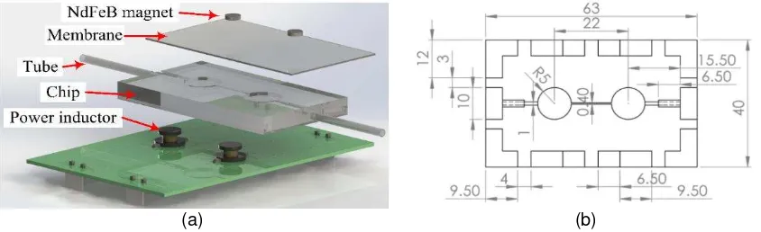
Figure 1(a) shows 3-D schematic illustration of the electromagnetic micropump setup and
Figure 1(b) shows the dimensions of the microchannel.
(a) (b)
Figure 1. Project design (a) Micropump setup (b) Microchannel design drawing in millimeter
As depicted in
Figure 1(a), the micropump consists of two separate modules: an actuation module and a microchannel (diffuser) module. A microchannel was designed and drawn by using SolidWorks® 3D CAD software (Dassault SystèmesSolidWorks Corp) as shown
Figure 2. Electromagnetic actuation operation, (a) Actuation response towards voltage and membrane position (b) schematic illustration of actuation during magnetized and repelled
condition
Figure 2(a) and (b) show the oscillation of a NdFeB magnet is influenced by the polarity of the supplied voltage to power inductor, either to attract (going down) or repel (going up) the magnet. In rest mode (no voltage supplied mode), there no is movement. When the positive polarity voltage is induced, the magnet is attracted towards the power inductor. The membrane is deflected to expel fluid through the channel. On the other hand, at negative polarity voltage, the magnet is repelled, resulting to the inflation of the membrane and thus sucks the fluid into the chamber. The continuous cycle of changing voltage polarities to attract and repel the magnet create a net fluid flow. Different frequency gives different flow rate. Similar pumping method have been done by Shen M. et.al [14], Zhi C. et.al [18] and Pan T. et.al [15], but the difference is the actuating element by using a rotating magnet, mesh type coils and a DC micro-motor to drive the fluid inside a microchannel.
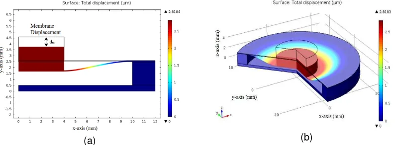
The numerical simulation studies the deflection properties of the membrane. The membrane displacement, dm is influenced by the surface contact ratio between the magnet and the membrane, and the thickness of the membrane, t. The maximum deflection of the membrane is studied using the finite element analysis (FEA) using COMSOL Multiphysics®
(COMSOL Inc, Burlington, USA). The density, Young’s modulus and Poisson’s ratio of the
PDMS material curing at room temperature are 965 kgm-3 [19], 1.32 × 10⁶ Pa [20] and 0.499 [20] .The NdFeB magnet parameters are 7500 kgm-3, 1.6 × 10¹¹ Pa and 0.24 respectively. The force was applied at 1 N on top of the magnet in – z direction.
Figure 3 illustrates one of the simulated results acquired for the membrane displacement at 0.4 surface contact ratios.
(a) (b)
Figure 3. Membrane deflection cause by body load at 0.4 contact ratio (a) View in 2D axis-symmetric (b) View in 3D
As depicted from
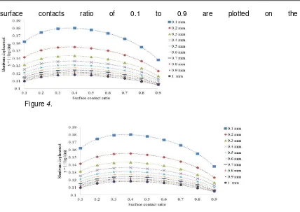
surface contacts ratio of 0.1 to 0.9 are plotted on the
Figure 4.
Figure 4. Semi-logarithm graph with the fitted line of the membrane displacement with variation of surface contact ratio for different membrane thickness
Figure 4 shows a Gaussian characteristic for all membrane thickness from 0.1 mm to 1 mm with the contact ratio from 0.1 to 0.9. The optimal deflection is observed at 0.4 contact surface ratio at all membrane thickness. Thus, for this experiment, the microchannel chamber is set to 10 mm in diameter and the magnet diameter of 4 mm (1:0.4).
3. Micropump Design and Fabrication
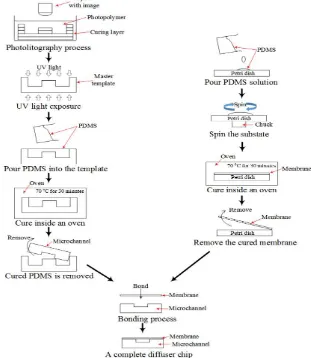
The designed microchannel consists of two elements: diffuser and membrane. The fabrication of a master template for the microchannel was using a rapid prototyping technology technique and the membrane was fabricated using a spin coated method. Figure 5 shows the fabrication process of the microchannel module. The custom master template (mould) was designed using computer aided design software. The design details can be referred in
Figure 5. Fabrication procedure of a microchannel module
A mechanical micropump needs an actuation membrane to drive the fluid inside the channel. This work uses the same material and same mixing ratio as the microchannel chip for the membrane fabrication. A digital spin coater machine with a spinner was used to yield a uniform prepolymer for the membrane. Thickness of a coated membrane is depended on the prepolymer weight, spin coater speed, spin time and also the viscosity of the prepolymer material. For this setup, the spin coater speed, spin time and prepolymer weight was fixed at 500 rpm, 120 s and 2.5 g to yield 325.9 µm of membrane thickness. Firstly, PDMS solution was being poured in a plastic petri dish. Then, it was placed in the spin coater machine for spinning process. After that, it was placed in an oven for curing process. Finally, the membrane was slowly peeled off from the petri dish.
The fabricated membrane and microchannel have the same surface properties; therefore, the bonding between the two items can be made by using the same material. A prepolymer mixture was rubbed on the surface between the bonded areas. The membrane was aligned and placed on top of the microchannel. The air bubbles, created during the bonding process were removed using a desiccator machine (F42025, Bel Art, New Jersey, USA) before curing at 70 ºC for 30 minutes[20].
Figure 6. Experiment setup under a zero backpressure
As shown in
Figure 6, the actuator module was controlled by a controller module, consist of an Arduino Uno microcontroller, a motor driver shield, buck converters and a push button module. Arduino Uno controls the switching speed of the power inductor from 1 Hz to 16 Hz. In addition, it also controls the direction of liquid flow inside the microchannel either in forward and reversed direction by turning on or off one of the power inductor. If the fluid want to flow in forward direction (from left to right), the controller only needs to send the signal to the right inductor while the left inductor is off and vice versa. The motor driver shield was used to control the polarity of the supplied voltage meanwhile buck converters was being used to step-down voltage from 12 Vdc to 1.5 Vdc for powering the power inductors. The medium used for the experiment was water. The inlet and outlet tubes were from a commercially available AlphaSil® silicon tubing with an inner diameter of 1 mm and outer diameter of 2 mm. It was assumed the flow is in non-slip condition.
4. Result and Discussion
The first evaluation to the proposed electromagnetic actuated system was studied on the velocity and flow rate performance under a zero backpressure condition.
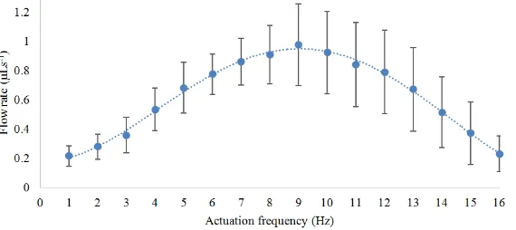
Figure 7 depicts the micropump performance profile at actuation frequencies from 1 – 16 Hz with 1 Hz resolution.
In
Figure 7. Flow rate vs. actuation frequency
Figure 8. Flow rate vs. backpressure
Figure 8 shows six configuration height levels from 0 – 10 mm with 2 mm resolution. From the experiment, the actuation frequency at 1 Hz can operate up to 2 mmH2O backpressure at 0.1587 µLs-1 of flow rate. The actuation frequency of 2 Hz is capable to withstand pressure up to 4 mmH2O at 0.1892 µLs-1.The frequencies from 4 – 9 Hz were still capable to flow the liquid up to 10 mmH2O but 3 Hz was up to 8 mmH2O only.
5. Conclusion
This paper introduces the preliminary study on the integration of power inductor into micropump system for bidirectional flow fluid. In the present study, an electromagnetic actuated valveless bidirectional flow micropump was developed. The micropump system is in modular based: the mirochannel part is replaceable. The driving frequency range was from 1 Hz to 16 Hz. The maximum volumetric flow rates were 0.9756 µLs-1 at 9 Hz under a zero backpressure. Even though the system only uses 5 Vdc supply, it is also require high current input in order to magnetize the actuators which causes some inconvenient in making the system as a portable device (supply from a battery is not recommended). Future works includes design improvements and optimization on the diffuser chip to achieve higher flow rates while maintaining the power usage at low voltage.
Acknowledgements
References
[1] GM Whitesides. The origins and the future of microfluidics. Nature. 2006; 442: 368-373.
[2] MJ Cima. Microsystem Technologies for Medical Applications. Annual Review of Chemical and
[5] A Manz, N Graber, HM Widmer, SC Terry, JH Jerman, JB Angell. Miniaturized total chemical analysis systems: a novel concept for chemical sensing. IEEE Transactions on Electron Devices. 1979; 26: microfabrication of a novel lab on a chip. 2011 Symposium on Design, Test, Integration & Packaging of MEMS/MOEMS (DTIP).2011: 372-374.
[9] JP Wikswo, FE Block, DE Cliffel, CR Goodwin, CC Marasco, DA Markov, et al. Engineering challenges for instrumenting and controlling integrated organ-on-chip systems. IEEE Transactions on Biomedical Engineering. 213; 60: 682-690.
[10] LJ Thomas, SP Bessman. Prototype for an implantable insulin delivery pump. Proceedings of the Western Pharmacology Society.1975; 18: 393-398.
[11] PS Chee, R Abdul Rahim, R Arsat, U Hashim, PL Leow. Bidirectional flow micropump based on dynamic rectification. Sensors and Actuators A: Physical. 2013; 204: 107-113.
[12] PS Chee, R Arsat, T Adam, U Hashim, RA Rahim, PL Leow. Modular architecture of a non-contact pinch actuation micropump. Sensors. 2012; 12: 12572-12587.
[13] Y Luo, M Lu, T Cui. A polymer-based bidirectional micropump driven by a PZT bimorph. Microsystem Technologies. 2011; 17: 403-409.
[14] M Shen, L Dovat, MAM Gijs. Magnetic active-valve micropump actuated by a rotating magnetic assembly. Sensors and Actuators B: Chemical. 2011; 154: 52-58.
[15] T Pan, E Kai, M Stay, V Barocas, B Ziaie. A magnetically driven PDMS peristaltic micropump.
Conference proceedings: Annual International Conference of the IEEE Engineering in Medicine and Biology Society. IEEE Engineering in Medicine and Biology Society Conference.2004; 4: 2639-2642. [16] MW Ashraf, S Tayyaba, A Nisar, N Afzulpurkar. MEMS based system for drug delivery. 82-87. [17] C Liguo, Y Liu, L Sun, Q Dongsheng, M Jijiang. Intelligent Control of Piezoelectric Micropump Based
on MEMS Flow Sensor. 3055-3060.
[18] C Zhi, T Shinshi, M Saito, K Kato. Planar-type micro-electromagnetic actuators using patterned thin film permanent magnets and mesh type coils. Sensors and Actuators, A: Physical. 2014; 220: 365-372.
[19] H Selvaraj, B Tan, K Venkatakrishnan. Maskless direct micro-structuring of PDMS by femtosecond laser localized rapid curing. Journal of Micromechanics and Microengineering. 2011; 21: 075018. [20] ID Johnston, DK McCluskey, CKL Tan, MC Tracey. Mechanical characterization of bulk Sylgard 184