DOI: 10.12928/TELKOMNIKA.v14i1.2394 471
Harmonic Suppression Rectangular Patch Antenna with
Circularly Polarized
Nurzaimah Zainol*, Zahriladha Zakaria, Maisarah Abu, Mawarni Mohamed Yunus Microwave Research Group, Centre for Telecommunication Research and Innovation (CeTRI), Faculty of Electronics and Computer Engineering, Universiti Teknikal Malaysia Melaka (UTeM),
76100 Durian Tunggal, Melaka, Malaysia
*Corresponding author, e-mail: [email protected]
Abstract
The rectangular patch antenna with proximity coupling at 2.45 GHz is designed and printed on
FR-4 substrate with dielectric constant
r
4.3 and loss tangent 0.019. The overall size of proposedantenna gives 36 % reduction of substrate area as compared to conventional designs. The symmetrical arm of inverted U-stub and U-slot embedded on the transmission feed line suppress harmonic signal effectively at second and third order with minimum reflection coefficients of –0.51 dB and -2.28 dB respectively while circularly polarization was obtained by corner truncated and U-slot on the patch element. The return loss is -23.95 dB at fundamental modes with gain 4.61 dB and axial ratio of 1.48 dB.
Keywords: circularly polarization (CP), harmonic rejection, microstrip patch antenna, rectenna and stub
Copyright © 2016 Universitas Ahmad Dahlan. All rights reserved.
1. Introduction
The rapid growth of wireless products and services in wireless communication field such as Bluetooth, GSM, satellite and military applications require flexible antenna to integrate with Active Integrated Antenna (AIA). This wireless communication systems modulate data at a resonant frequency and being used in energy scavenging to convert radio frequency (RF) energy to DC voltage or vice versa. The component used for energy conversion in energy harvesting system known as rectenna where it consist an antenna, low pass filter, diode and load.
The wireless power transfer system must operate efficiently and the losses of energy during receiving and conversion of signal processes should be minimized by suppressing the undesired signal. However, the interface between the antenna and the nonlinear circuit component such as diode [1-2] or FET for active integrated antenna (AIA) or rectenna system has a harmonic suppression filter which require extra space for installation. Then, the antenna harmonic suppression is used to avoid spurious radiation that easily produced at high-order resonant frequencies of the antenna from the circuits [3]. This weak signal then flow to the rectifier circuit for the RF-to-DC conversion and the process is repeated caused the output of the rectenna is low for wireless power transfer system [4-7]. Research findings in [8] highlighted that the input impedance of the antenna design would allow the second harmonic at high-order frequency which occurs at twice of its design frequency and these degrade the antenna performance in term of minimum reflection coefficients and total gain. However, higher order harmonic can be blocked as input impedance at higher order almost zero or unmatched.
In brief, various harmonic rejection techniques associated with their design discrepancy have been reviewed extensively in order to obtain harmonic rejection property. These findings supported in [9-10], a photonic band gap structure and shorting pin [11] can be used to block high harmonics. An unbalanced circular slot on the circular patch [12], and four right angle slit [13] also have capabilities to reject the harmonics signal and attain circularly polarized antenna. The parametric studies on each design parameter of the slots, slits and stubs need to be done and were carefully optimized until achieve good results in terms of return loss, harmonic rejection performance and axial ratio.
configuration with harmonic rejection is presented for rectenna application. The symmetrical inverted arm U-stub and U-slot on the transmission feed line were examined as harmonic rejection technique both at second and third order. Then, the circularly polarization realized by cutting the corner of the rectangular patch and U-slot embedded on its radiating element. The design process will discussed further with their relevant results obtained.
2. Antenna Design
This section discusses the antenna geometry by examining the antenna design based on transmission line model. The antenna is constructed using FR-4 on a 1.6 mm of substrate thickness with dielectric constant
r
4.3 and loss tangent 0.019. The dimension of rectangular microstrip patch antenna can be determined using formula given in [14].2
= dielectric constant of substrate
eff
L = Effective length
reff
= Effective dielectric constant of patch
(a) (b)
(c)
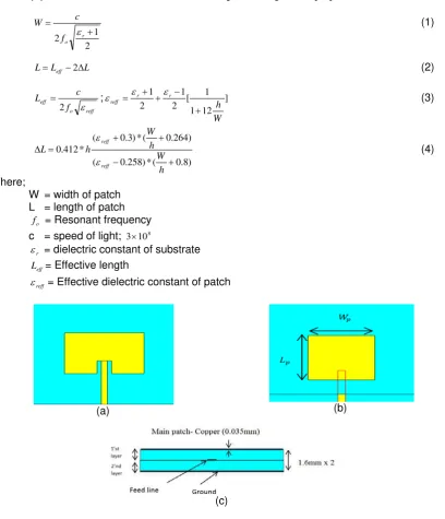
Figure 1. Design geometry; (a) Conventional microstrip rectangular patch antenna; (b) Improvement for the conventional patch antenna with proximity coupling for overall size
Figure 1(a) shows the geometry of the conventional microstrip rectangular-patch antenna whereas Figure 1(b) demonstrated the design improvement made to reduce the overall size and weight of the rectenna. Thus, in this design the proposed antenna structure is fed by proximity coupling with double layer substrate as shown in Figure 1(c) and yields 36 % of overall size reduction when compared with the conventional design. The main features of the design parameter are recorded in Table 1 whereas Table 2 shows the purpose of proposed antenna to make it compact. The first layer of substrate for the proposed antenna in proximity coupling is 55 mm x 60 mm whereas its second layer is 60 mm x 60 mm.
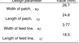
Table 1. Design parameter of rectangular patch antenna in stack configuration
Design parameter Value (mm)
Width of patch,
Table 2. Performances comparison between conventional antenna and the proposed antenna in stacked configuration
Design Overall size (mm) Size of patch element (mm) Conventional Rectangular Patch Antenna 69 x 71 38 x 28.9 Rectangular Patch Antenna with Proximity coupled 60 x 60 26.7 x 24.8
2.1. Harmonic Rejection Techniques
The proposed design provides simple harmonic rejection techniques where the feed line area on the second layer of substrate is examined to block harmonics rather than other method used in literature studies [15]. Figure 2(a) depicts the initial structure of feed line in proximity coupling whereas Figure 2(b) illustrates its harmonic rejection technique adopted on the feed line using U slot. Design parameter “d” denotes the distance of U slot from input port is 5 mm and it is positioned at optimum values. The length of U slot represented by Lu1 and Lu2 whereas
Wu used to represented the width of slot. The parametric studies involved on each design
parameter for U slot is studied for the purpose of harmonic rejection. Table 3 summarized the significance effect on resonant frequency by varying the length, Lu2 of the U slot. It shows that
the return loss performance is improved when the length is increase and the resonant frequency shifting to high frequency. The optimum values associated with better rejection capabilities for Lu2 is 5.0 mm whereas the width used is 0.5 mm respectively. The significance results for Lu1 is
carried out for 1.5 mm, 2.0 mm and 2.5 mm and thus the optimum result achieved when Lu1 is
2.0 mm. The deep resonance exhibit near third order at 7.37 GHz with minimum reflection coefficient of -33.3 dB is suppressed effectively using U slot up to acceptable range.
Then, the overall performance for antenna is improved by removing the harmonic signal exhibit near the second order using symmetrical arm of inverted U stub with 0.5 mm width outside the transmission feed line. This symmetrical arm of inverted U stub as shown in Figure 2(c) was created at the middle of Lu2 for equal power transfer and the optimum values for Ls1=1
mm, Ls2=1.5 mm, Ls3=3.5 mm and Ls4=2.0 mm was used to represent the length for it. Figure 3
shows the minimum reflection coefficients performances of the rectangular patch in stacked configuration with harmonic rejection techniques adopted on the feed line. As a result, the combination of both techniques gives better harmonic rejection until spurious radiation is suppress up to greater than -3 dB and improve the system performance.
Table 3. Parametric studies on Lu2 of U slot on the feed line
(a) (b) (c)
Figure 2. View of transmission feed line; (a) Initial feed line, (b) Feed line with U slot, (c) Combination of U slot and symmetrical arm of inverted U stub
Figure 3. Minimum reflection coefficients performances of the rectangular patch in stacked configuration with harmonic rejection techniques adopted on the feed line
2.2.Harmonic Suppression Antenna with Circularly Polarized
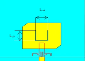
Microstrip patch antenna with circularly polarization can be obtained with slight modification to the radiating element [16]. In this design, by cutting the corner of patch element and U slot embedded on it as shown in Figure 4 can realize this objective with simple method applied. The design parameter of Lu3 and Lu4 used to represent the length of U slot on the patch element. The parametric analysis was carried out to seek the best result and Table 4 recorded the data obtained. From this, the resonance frequency is shifting with varying the length of U slot and the optimum value used for Lu3 is 10 mm and Lu4 is 8.85 mm. The truncated patch is cutting by 6 mm each side to get the optimum result.
Figure 4. Harmonic suppression antenna with circularly polarization
Table 4. Parametric studies on Lu3 of U slot on the patch element
Frequency (GHz) Return Loss (dB) LU3 (mm)
2.450 -23.950 8.85
2.455 -23.977 10
In first attempt, the antenna harmonic suppression is linear polarized with axial ratio of 19.36 dB. The patch elements radiate primarily linear polarized waves; however, by introducing U-slot and cutting the corners of patch element, attain circularly polarized antenna. As a result, the simulated axial ratio of the proposed design yield 1.48 dB < 3 dB as shown in Figure 5. Thus, the antenna design is a good choice for wireless power transfer application since circular polarized system is more suitable in several cases due to its insensitivity to both transmitter and receiver orientation. Hence, the polarization mismatch or any loss between it can be minimized by circularly polarized antenna as it gives stable DC voltage irrespectively to its rotation [17-18].
Figure 5. The simulated axial ratio of the proposed design
3. Result and Discussions
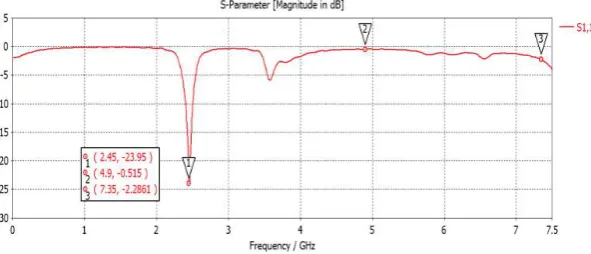
Figure 6 illustrates the minimum reflection coefficient of the proposed antenna harmonic suppression with circularly polarization at 2.45 GHz. From this figure, it shows antenna have good return loss with -23.95 dB at fundamental modes and better harmonic rejection performance at second and third order since suppress up to -0.51 dB and -2.28 dB respectively. From Figure 7(b) and Figure 7(c), clearly shows current distribution were block at symmetrical arm of inverted U-stub and U-slot areas at second and third order effectively. Findings in [19] revealed that surface wave can change the amount of current flow on each element and thus make antenna radiation pattern different too. Based on radiation pattern displayed in Figure 8, the main lobe magnitude for the antenna design is 6.4 dBi at 6.0 degree direction from the origin point. The antenna radiated in specific direction with smaller HPBW 93.4 degree due to thin substrate used. Then, the performance of proposed antenna was analyzed as displays in Figure 9(a) and Figure 9(b) with 6.4 dBi of its directivity and offer high gain 4.61 dB. A novel study in [20] also demonstrated the proximity coupled rectangular patch design with corner truncated for circular polarization at 2.25 GHz. However, the stub was deployed for matching impedance bandwidth. Surprisingly, the 4x1 arrays yield 9.281 db which is moderate for array arrangement compare with this work which use inexpensive material but offer high gain for single element.
(a) 2.45 GHz (b) 4.9 GHz (c) 7.35 GHz
Figure 7.Electric current distribution in proposed antenna structure
Figure 8. Radiation pattern of the antenna design
(a) Directivity (b) Gain
Figure 9. Directivity and the gain of antenna design
4. Conclusion
A miniaturized antenna harmonic suppression with advantage of circularly polarization is presented in this paper. The proposed antenna design performed harmonic rejection capabilities using combination of symmetrical inverted arm of U-stub and U-slot on the feed line up to -0.51 dB and -2.28 dB respectively at second and third order. The proposed antenna provides -23.95 dB of minimum reflection coefficient and offer high gain 4.61 dB at 2.45 GHz. This antenna design with proximity coupling effectively reduced 36% of the overall size and 66% of the radiating element area when compared with the conventional patch antenna. Thus, the study can be further explored by implementing a prototype of the antenna harmonic suppression to validate its concept and this new structure would be useful for RF-front-end subsystems as well as providing an attractive solution for the miniaturization of the overall physical dimensions.
Acknowledgements
our work. The work was supported by UTeM under research grants RAGS/2013/FKEKK/TK02/ 02/B00031.
References
[1] Dasgupta S, Gupta B, Saha H. Development of Circular Microstrip Patch Antenna Array for Rectenna
Application. IEEE INDICON. 2010.
[2] Riviere S, Alicalapa F, Douyere A, Lan Sun Luk JD. A Compact Rectenna Device at Lower Power
Level. Progress in Electromagnetics Research C. 2010; 16: 137-146.
[3] Yin X, Zhang H, Huang XY, Xu HY. Spurious Modes Reduction in a Patch Antenna using an
EBG-Based Microstrip Transmission Line Filter. Progress in Electromagnetics Research C. 2012; 25:
41-54.
[4] Xiao S, Jiang L, Wang BZ, Wang J. A Millimeter Wave Microstrip Antenna Array with Harmonics Suppression Elements. IEEE. 2008.
[5] Xu Y, Gong S, Guan Y. Coaxially Fed Microstrip Antenna for Harmonic Suppression. Electronics
Letters. 2012; 48(15).
[6] Zhang Z, Jiao YC, Weng ZB. Design of 2.4GHz Power Divider with Harmonic Suppression.
Electronics Letters. 2012; 48(12).
[7] Czarnecki LS. An Overview of Method of Harmonic Suppression in Distribution Systems. IEEE. 2000. [8] Radisic V, Chew ST, Qian Y, Itoh T. High-Efficiency Power Amplifier Integrated with Antenna. IEEE
Microwave and Guided Wave Letters. 1997; 7(2).
[9] Hassan N, Ahmad BH, Zoinol M, Zakaria Z. Microstrip Patch Antenna with a Complementary Unit of Rhombic Split Ring Resonator (R-SRR) Structure. World Applied Sciences Journal 21(Special Issue
of Engineering and Technology). 2013: 85-90.
[10] Liu H, Li Z, Sun X, Mao J. Harmonic Suppression with Photonic Bandgap and Defected Ground Structure for a Microstrip Patch Antenna. IEEE Microwave and Wireless Components Letters. 2005; 15(2).
[11] Melha MS, Abd-Alhameed RA, See CH, Usman M, Elfergani ITE, Noras JM. Harmonic Rejection
Triangle Patch Antenna. PIERS Proceedings.Kuala Lumpur, MALAYSIA. 2012: 1514-1517.
[12] Pogorzelski RJ. An Effective Method of Isolating Portions of a Radiator in Near-Field or Far-Field Antenna Measurements. IEEE Antennas and Propagation Magazine. 2013; 55(3): 156-168.
[13] Huang FJ, Yo TC, Lee CM, Luo CH. Design of Circular Polarization Antenna with Harmonic Suppression for Rectenna Application. IEEE Antennas and Wireless Propagation Letters. 2012; 11. [14] Ghosh CK, Parui SK. Design, Analysis and Optimization of A Slotted Microstrip Patch Antenna Array
at Frequency 5.25 GHz for WLAN-SDMA System. International Journal on Electrical Engineering and
Informatics. 2010; 2(2).
[15] Sabran MI, Rahim SKA, Rahman TA, Eteng AA, Yamada Y. U-Shaped Harmonic Rejection Filtenna
for Compact Rectenna Application. Proceedings of Asia-Pacific Microwave Conference. 2014: 1007-
1009.
[16] Lam KY, Luk KM, Lee KF, Wong H, Ng KB. Small Circularly Polarized U-Slot Wideband Patch Antenna. IEEE Antennas and Wireless Propagation Letters. 2011; 10.
[17] Wang YQ, Yang XX. Design of a High-Efficiency Circularly Polarized Rectenna for 35 GHz Microwave Power Transmission System. IEEE. 2012.
[18] Barrera OA, Lee DH, Quyet NM, Hoang-The V, Chang Parl H. A Circularly Polarized Harmonic-Rejecting Antenna for Wireless Power Transfer Applications. IEICE Electronics Express. 2013; 10(19): 1-6.
[19] Ningsih YK, Hadinegoro R. Low Mutual Coupling Dualband MIMOMicrostrip Antenna Parasitic with Air Gap. TELKOMNIKA Telecommunication Computing Electronics and Control. 2014;12(2): 405-410. [20] Darsono M, Wijaya E. Circularly Polarized Proximity-Fed Microstrip Array Antenna for Micro Satellite.