accredited by DGHE (DIKTI), Decree No: 51/Dikti/Kep/2010 167
Performance of Subcarrier and Power Allocation
Orthogonal Frequency-Division Multiplexing on
Millimeter Wave
Naemah Mubarakah1, Rika Wahyuni Arsianti 2, Mulyadi3
1
Department of Elecrical Engineering, North Sumatra University, Medan
2
Department of Electrical Engineering, State Polytechnic of Medan, Medan
3
Departement of Electrical Engineering, Borneo University, Tarakan
e-mail:[email protected]
Abstrak
Pemenuhan kebutuhan bit rate diatas 40 Mbps dapat dilakukan dengan sistem local multipoint distribution service (LMDS) yang dioperasikan pada gelombang milimeter. Sistem ini mempunyai masalah tersendiri ketika diterapkan pada daerah dengan potensi curah hujan yang cukup tinggi, seperti Indonesia. Untuk itu sistem LMDS dikembangkan dengan mekanisme cross-layer. Pada penelitian ini teknik yang digunakan pada cross-layer orthogonal frequency-division multiplexing (OFDM) multi-user adalah joint subcarrier and power allocation (JSPA). Diharapkan kinerja sistem telekomunikasi pada kanal gelombang millimeter meningkat meski terjadi gangguan oleh redaman hujan. Penelitian ini membahas kinerja kapasitas transmisi, data rate, utility dan fairness dari algoritma JSPA yang diterapkan dari hasil penelitian pengukuran redaman hujan di wilayah Surabaya. Dari hasil penelitian diperoleh adanya peningkatan kinerja sistem melalui teknik JSPA. Pada kondisi redaman hujan yang mencapai 40dB, teknik JSPA mampu meningkatkan kapasitas rata-rata transmisi mencapai 173,3%, data rate sistem mencapai 189,9% dan fairness sistem mencapai 9,6%. Implementasi teknik JSPA dapat meningkatkan utility system hingga 13,61-15,48 bps/Hz.
Kata kunci: alokasi daya, alokasi subcarrier, kanal gelombang millimeter, OFDM, LMDS
Abstract
Local multipoint distribution system (LMDS) that operated in millimeter waves can be used to fulfill the need of bit rate higher than 40 Mbps. However it has problem when applied in tropic country such as Indonesia because of the high rainfall. Therefore LMDS system was developed by cross-layer mechanism. In this research we used joint subcarrier and power allocation (JSPA) technique in multi-user cross-layer OFDM. This technique is proposed to increase the performance of telecommunication system even there were disturbance of rain attenuation. The research is discussing the performance of transmission capacity, data rate, utility and fairness of JSPA algorithm that applied in rain attenuation measurement in Surabaya. The result shows the increment of performance system using JSPA technique. For 40 dB rain attenuation, JSPA can achieves respectively average capacity of transmission up to 173,3%, 189,9 % for data rate and 9,6% for fairness system. The application of JSPA technique improve the performance of utility 13,61-15,48 bps/Hz
Keywords: power allocation, subcarrier allocation, millimeter channel waves, OFDM, LMDS
1. Introduction
The development of broadband services technology increased rapidly. Services that require the availability of high speed data channels such as high speed internet, digital video, audio broadcasting and video conferencing continues to increase. The need for the provision of high speed data channel can be performed with localmultipoint distribution service (LMDS).
The novel mechanism to increase the quality and capacity of system is cross-layer mechanism approach [2] [3]. It is developed the integrated framework at Physical (PHY) layer and media access control (MAC) layer.
Cross-layer Approach in multiuser orthogonal frequency-division multiplexing (OFDM) can be obtained by using the joint subcarrier and power allocation (JSPA) technique and Adaptive Packet Scheduling. These are support by the availability Channel State Information (CSI) and Arrival Traffic Information. The previous research was study the joint subcarrier Allocation and power on channel-aware queue-aware (CAQA) [4] and Resource Allocation and Cross-layer Scheduling on multicarrier wireless network [5] [6].
The application of JSPA technique on millimeter wave transmission is interrupted by rain attenuation. Rain attenuation measurements have been performed using optical disdrometer gauges placed at ITS Surabaya [7]. This study is aim to know the benefits of JSPA techniques for improving performance system on broadband networks in tropical countries, especially Indonesia to increase the capacity, data rate, utility and fairness.
2. Research Method 2.1. Rainfall Measurement
Precipitation measurements performed in Surabaya using an optical disdrometer gauges are placed on the roof of the Telecomunication Laboratorybuilding. Optical Disdrometer work based laser systems, optical sensor with 180 mm wide x 30 mm. Measurements can be performed in real time, if there is a rain particle passing through the laser beam to detect disdrometer rainfall (mm/h) and the distribution of rain. Then the results are stored in software (Hydras and ASDO) called data parsivel shaped rainfall data and txt files. Data obtained from these measurements ASDO rain in software [7].
2.2.Generation Attenuation Rain
The result of rain attenuation measurement in Surabaya with the distance between user and transmitter 1-3 miles:
Stage 1: Generating the value of m, σ for four users based distance randomly generated by taking as reference the data in Table 1 [7].
Table 1. The average and standard deviation of SST log rain attenuation Link Length(km) Average () Standard deviation ()
1 -1,0539 2,0574
2 -0,4554 2,1248
3 -0,1321 2,1719
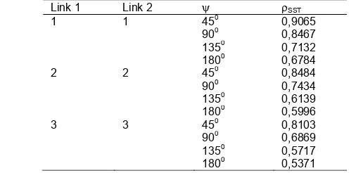
Stage 2: Generating the coefficients of rain attenuation randomly by taking the reference data in Table 2 [7].
Table 2. The correlation of rain attenuation using the calculation of rain attenuation SST
Link 1 Link 2 SST
1 1 450 0,9065
900 0,8467
1350 0,7132
1800 0,6784
2 2 450 0,8484
900 0,7434
1350 0,6139
1800 0,5996
3 3 450 0,8103
900 0,6869
1350 0,5717
step 3 : Prepare 4x4 covariance matrix:
Where [8] :
SST a n m b b
m n m
n ln exp exp 1 exp 1 exp
1 2 2
,
(4)
2 2
2
2 n m n m
a (5)
2 2 2 2 m n m n
b (6)
μ is the average (mean), σ is the standard deviation, ρSST SST is rain attenuation coefficient, ρn, m is the attenuation coefficient of normal rainfall, n and m are the links 1 and 2.
Step 4: Obtain the rain attenuation value of each user by the equation:
A = exp (X) (7)
x
x Y m
C
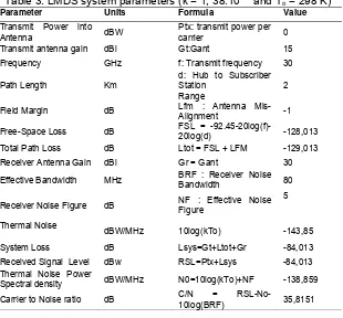
X 1/2 , A as the rain attenuation values, y is a matrix of 4 1 Gaussian ( = 0 and 2 = 1) and m is a vector of m. Then enter the data for LMDS system parameters that can be seen in Table 3 [9].
Table 3. LMDS system parameters (k = 1, 38.10-23 and To = 298 K)
Parameter Units Formula Value
Transmit Power into
Antenna dBW
Ptx: transmit power per
carrier 0
Transmit antenna gain dBi Gt:Gant 15
Frequency GHz f: Transmit frequency 30
Path Length Km
d: Hub to Subscriber Station
Range
2
Field Margin dB Lfm : Antenna
Mis-Alignment -1
Free-Space Loss dB FSL =
-92.45-20log(f)-20log(d) -128,013 Total Path Loss dB Ltot = FSL + LFM -129,013
Receiver Antenna Gain dBi Gr = Gant 30
Effective Bandwidth MHz BRF : Receiver Noise
Bandwidth 80
Receiver Noise Figure dB NF : Effective Noise Figure
5
Thermal Noise
dBW/MHz 10log(kTo) -143,85
System Loss dB Lsys=Gt+Ltot+Gr -84,013
Received Signal Level dBw RSL=Ptx+Lsys -84,013 Thermal Noise Power
Spectral density dBW/MHz N0=10log(kTo)+NF -138,859 C/N =
2.3. Joint Subcarrier and Power Allocation (JSPA)
OFDM-based LMDS systems are applied in millimeter wave channel, channel conditions (pi (f)) which varies depending on the weather, making it necessary for performance
optimization subcarrier allocation and power allocation. Dynamic Subcarrier Allocation (DSA) applied for Subcarrier allocation and Adaptive Power Allocation (APA) for Power allocation. JSPA simultaneously to optimize cross-layer to reach the optimum achievable value of fairness. The combined DSA and APA optimization can be formulated with [5] [6]:
df f f p U M r UM D i
M i i M i i i i ) ( ) ( 1 log 1 ) ( 1 * 2 1 1 (8)
p * (f) = power emitted optimum.
2.3.1. Dynamic Subcarrier Allocation (DSA)
The purpose of the DSA is to improve the performance of OFDM-based network when the transmission power is uniformly distributed throughout the frequency band. To calculate the capacity ci(f) is transmitted can be formulated by [5]:
) ( ) ( 1 log ) ( 2 2 f N f H p f c i i i
(9)
Hz bps f f p f
ci( ) log2(1 ( )i( )) (10)
is a constant value to give the desired BER, can be formulated by:) 5 ln( 5 , 1 BER
(11)
and
i(
f
)
is a subscriber channel conditions on the frequency f of the user i, where:) ( ) ( ) ( 2 f N f H f i i i
(12)
)
(
f
H
i is the channel gain at user i at subcarrier frequency f and Ni (f) is the noise power at user i at subcarrier frequency f.If the transmitted power normalized, where p (f) = 1, then to achieve the capacity of the frequency f, ci (f), can be expressed in Equation 13.
)) ( 1 ( log )
(f 2 f
ci
i (13)Each user or each session has a weight expressed as CSI and related queuing time. The weight indicates the utility function used for optimization crosslayer and the balance between efficiency and fairness. For best effort traffic (non-real time traffic) adopted a utility function with r = x kbps and is given by:
) 3 , 0 ln( 8 , 0 16 , 0 )
(r r
U (14)
U(r) is value of utility.
Di
i M i i M i i
i U c f df
M r U
M ( )
1 ) ( 1 1 1 (15)
M is number of user. The total number of M user subcarrier is the total available bandwidth that can be formulated as follows:
M i B Di 1 , 0 (16) M j i j i DDi
j , dan , 1,2,...,(17) Di is subcarrier for user i and ri is the data rate of user i.
2.3.2. Adaptive Power Allocation (APA)
In order to obtain the BER quality of signal information we optimized the APA performance, Water-filling algorithm is used as a function to obtain the optimal power allocation. In this theorem, fixed subcarrier allocation is known; the optimum power allocation is equation [5]:
f r U f p i i i 1 * ' * (18)
is constanta of normalized optimal power density.
0
,
0
0
,
x
x
x
x
f
p
*Is optimal power density and *
i
r is value of optimal bit-rate [5].
Optimal resource allocation can not be directly calculated by the equation above that required an iterative algorithm. In the water-filling algorithm each user has a particular value of marginal utility, power obtained is compared to the total transmit power per user power. If the achievement of throughput as a function of power allocation, then:
df
f
p
f
f
c
i D i i)
(
)
(
1
(
log
)
(
* 2
(19)Utility is the data transmission capacity that is formulated:
)
3
.
0
ln(
8
.
0
16
.
0
)
(
r
r
U
(20)f
n
ci
r
(
).
andk
B
f
U (r) is expressed as a utility value, B is the bandwidth and k is the number of subcarriers for all users. The ultimate purpose of the APA is to maximize the value of fairness that is the average of all utility users, namely:
M i Ui ri M 1 ( )
1
3. Results and Analysis
The data generated under 3 km from the BTS to the user based on table 1. Simulation results for an area with less than 3 km from the BTS cannot be raised more than 4 users due to a very large correlation damping. User limited to four with 900 for each.
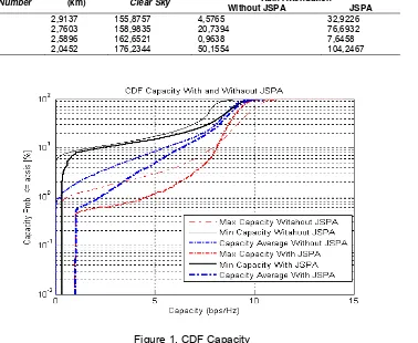
Parameters influenced JSPA technique on millimeter wave are capacity, data rate, utility and fairness. Table 4 shows a comparison of the capacity of clear sky conditions and the condition affected rain attenuation with JSPA and without JSPA techniques.
Table 4. Comparison of the capacity of clear sky conditions and the effect of rain attenuation with JSPA and without JSPA techniques.
User Number
Distance (km)
Capacity (bps/Hz)
Clear Sky Rain Attenuation
Without JSPA JSPA
1 2,9137 7,79379 0,2347 1,6582
2 2,7603 7,9492 1,0636 3,6939
3 2,5896 8,1326 0,0494 0,4180
4 2,0452 8,8117 2,5721 4,9424
From table 4 shows the average capacity without JSPA technique is 0.9799 bps / Hz. Meanwhile with JSPA techniques is 2.6781 bps / Hz. This means that the capacity increase 1.6982 bps / Hz. This is because the JSPA technique is applied adaptive power allocation. Simulation performed 10,000 times iterations for more accurate results, it show in figure 4 and 5. With JSPA techniques the capacity of the average value increases from 1.002 to 10.49 bps / Hz.
Table 5. Comparison of data rate
User Number
Distance (km)
Data Rate (Mbps)
Clear Sky Rain Attenuation
Without JSPA JSPA
1 2,9137 155,8757 4,5765 32,9226
2 2,7603 158,9835 20,7394 76,6932
3 2,5896 162,6521 0,9638 7,6458
4 2,0452 176,2344 50,1554 104,2467
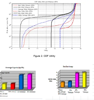
Figure 2. CDF Utility
Table 6 showsthat the average data rate without JSPA technique is 19.1088 Mbps and with JSPA increase to 36.2683 Mbps. Implementation of Power Allocation in JSPA technique cause increasing of data rate.
Data rate value equal to the system utility. The greater the value of its utility it shows the better performance of the system. This is because the utility associated with the value of efficiency and fairness. JSPA techniques increased the average utility value to be 13.61 to 15.49 bps / Hz.
Table 6. Utility Comparison
User Number
Utility
Without DSA, APA and JSPA
DSA APA JSPA
1 12,4292 12,4197 14,0136 14,0077
2 13,6380 13,7029 14,6543 14,6843
3 11,1829 11,0890 12,9111 12,9397
Fairness values obtained from the average utility for all users. The application of JSPA technique increases the fairness system. In clear sky condition fairness is 99.99% above 15,25. While the condition affected rain attenuation without JSPA technique fairness above 15 only 86.99% and fairness increase 2.4% by using JSPA technique. Table 7 shows the comparison of fairness system affected rain attenuation.
Table 7. Comparison of 4 user fairness system
Condition Fairness
Clear sky 15,2887
Attenuation Rain without JSPA 12,8987 Attenuation Rain using JSPA 14,1404
The comparison of capacity, data rate, and fairness utility of JSPA technique shows better performance improvement then without JSPA technique.
4. Conclusion
JSPA technique can increase the average of capacity to 1,002 – 10,49 bps/Hz because it has adaptive power allocation. For average of capacity above 7,7 bps/Hz JSPA technique increases up to 9,24%.
The application of JSPA technique improve the performance of data rate and utility respectively 36,283 Mbps and 13,61-15,48 bps/Hz.
For the fairness value, it just 86,99% reached 15 in affected rain attenuation condition without JSPA and fairness increase 2,4% ug JSPA technique.
The implementation of JSPA technique in OFDM downlink system at millimeter wave is recommended for area within high intensity of rain.
References
[1] Jun Y Zang, Ben Letaief K. Cross-layer Adaptive Resource Management for Wireless Packet
Network with OFDM Signaling. IEEE Transactions on Wireless Communications. 2004; 5(11):
3244-3254.
[2] Jun Y Zhang, Ben Letaief K. Adaptive Resource Allocation and Scheduling for Multiuser
Packet-based OFDM Networks. IEEE International Conference on Communications. 2006. 3(15):1565-1575.
[3] Mohanram C, Hashyam S. Joint Subcarrier and Power Allocation in Channel-Aware Queue-Aware
Scheduling for Multiuser OFDM. IEEE Transaction on Wireless Communications. 2007; 6(9).
[4] Song G, Ye Li. Cross-layer Optimization for OFDM Wireless Networks-part I: Theoretical Framework.
IEEE Transaction on Wireless Communications. 2005; 4(2): 614-624.
[5] Song G, Ye Li. Cross-layer Optimization for OFDM Wireless Networks-Part II: Algorithm
Development. IEEE Transaction on Wireless Communications. 2005; 4(2): 625-634.
[6] Chu CY, Chen KS. Effects of Rain Fading on the Efficiency of the Ka-Band LMDS System in the
Taiwan Area. IEEE Transaction on Vehicular Technology. 2005; 54(1): 9-19.
[7] Salehudin M, Hanantasena B, Wijdeman L. Ka Band Line-of-Sight Radio Propagation Experiment in
Surabaya Indonesia. 5th Ka-Band Util. Conference.Taormina.1999:161-165.
[8] Mahmudah H. Prediksi Redaman Hujan Menggunakan Synthetic Storm Technique. Ph.D. Thesis.