MAGNETIC BRAKE DESIGN AND SIMULATION
MOHD SUFFIAN ABDUL MUES
DECLARATION
“I hereby declared that I have read through this thesis and found that it has comply the partial fulfillment for awarding the degree of Bachelor Mechanical Engineering
(Automotive)”
Signature : ………
MAGNETIC BRAKE DESIGN AND SIMULATION
MOHD SUFFIAN ABDUL MUES
This thesis is submitted to the Faculty of Mechanical Engineering, in partial fulfillment of the partial requirement for the Bachelor of Mechanical Engineering (Automotive)
FACULTY OF MECHANICAL ENGINEERING UNIVERSITI TEKNIKAL MALAYSIA MELAKA
DECLARATION
“I hereby declared that this thesis is my original work except for questions and citations, which have been duly acknowledgment”
Signature : ………
iii
DEDICATION
To my beloved mother, father, brother and sister, and all my friends All member of Bachelor of Mechanical Automotive (BMCA)
My PSM supervisor, Mr. Mochamad Safarudin All lecturers from BMCA and FKM department
Staff of Faculty Mechanical Engineering
ACKNOWLEDGEMENTS
Alhamdulillah, I have successfully succeeded completing my PSM report. Firstly and most importantly, I would definitely want to grant a lot of thank and syukur to Allah S.W.T because giving me the blessing, opportunity and strength to complete my PSM report successfully. Not to forget my family especially to my mother and father which have supported me endlessly. Their support for me really gave me the strength and courage in completing this final year project.
I would like to take this opportunity to appreciate and thank Mr. Mochamad Safarudin; my final year project lecturer and supervisor for all his help and guidance which help me a lot in my report and project. I would also want to thanks all my classmates for their help and support.
Not forgetting to mention other lecturer which had helped me directly or indirectly from their advise, opinion and classes.
v
ABSTRACT
ABSTRAK
vii
CONTENT
CHAPTER TITLE PAGE
DECLARATION ii
DEDICATION iii
ACKNOWLEDGEMENT iv
ABSTRACT v
ABSTRAK vi
CONTENT vii
LIST OF FIGURE xii
LIST OF TABLE xiv
LIST OF APPENDIX xiv
LIST OF GRAPH xv
LIST OF SYMBOLS xvi
CHAPTER 1 INTRODUCTION 1
1.0 Introduction 1
1.1 Scope 2
1.2 Objective 2
CHAPTER TITLE PAGE
CHAPTER 2 LITERATURE REVIEW 4
2.1 Introduction to Brake 4
2.2 Types of Brakes 5
2.2.1 Friction Brakes 5
2.2.2 Electric Brakes 6
2.2.3 The Air Brake System 6
2.2.4 The Hydraulic Brake System 7
2.2.5 The Vacuum Brake System 7
2.3 Disc Brake 8
2.4 Magnets 9
2.4.1 Magnets attract some materials. 9
2.4.2 Magnet Magnetic Field. 10
2.4.3 Magnets Conduct Electricity 10 2.4.4 Magnetic fields are produced 11 by moving charges.
2.4.5 An electromagnet is made with a 12 coil of current-carrying wire wrapped
around an iron core.
ix
CHAPTER TITLE PAGE
CHAPTER 3 METHADOLOGY 14
3.0 Concept Design 15
3.0.1 Basic Design Principle 15
3.0.2 The Disc 16
3.0.3 The Caliper 17
3.0.4 Caliper Parts 20
3.0.4a Front Casing 20
3.0.4b Back Casing 20
3.0.4c Cast Magnet /Electromagnet 21
3.0.4d Permanent Magnet 21
3.0.4e The Solenoid Section 22 3.0.5 The Mechanism and How the 23 Brake Function
3.0.5a Symbol 23
3.0.5b Basic Principal Use 23
3.0.5c Not Braking 24
3.0.5d Braking 25
3.1 Calculation and Analysis 26
3.1.1 Wheel Velocity 27
3.1.2 Braking Energy 29
3.1.3 Power 29
3.1.4 Initial Torque 31
3.1.5 Energy Source 32
3.1.6 Final Calculation and Analysis result 33
3.2 Simulation 34
CHAPTER TITLE PAGE
CHAPTER 4 SIMULATION 35
4.0 Introduction 35
4.1 Mathematical Model and Parameter 36
4.1.1 Mathematical Model 36
4.1.1.1 Vehicle Lateral Motion 36 4.1.1.2 Vehicle Longitudinal Motion 38
4.1.1.3 Wheel and Brake 40
4.1.2 Simulation Parameter 41
4.2 SIMULINK Model 42
4.2.1 Vehicle Model 42
4.2.2 Half Car Model 43
4.2.2.1 Vehicle Lateral Motion (Lateral and 44 YawDynamic)
4.2.2.2 Vehicle Longitudinal Motion 44 (Longitudinal Dynamic)
4.2.3 Wheel Dynamic Model 45
4.2.4 Brake Dynamic Model 45
4.2.5 Longitudinal Slip (Front and Rear) 46 4.2.6 PID Controller (Front and Rear) 46
CHAPTER 5 RESULT AND DISCUSSION 49
5.0 Front Wheel Result 51
5.1 Rear Wheel Result 53
xi
CHAPTER TITLE PAGE
CHAPTER 6 CONCLUSION 57
REFERENCE 58
LIST OF FIGURE
FIGURE TITLE PAGE
1 Magnetic Brake 1
2 Basic Disc Brake Parts 8
3 Electromagnet 12
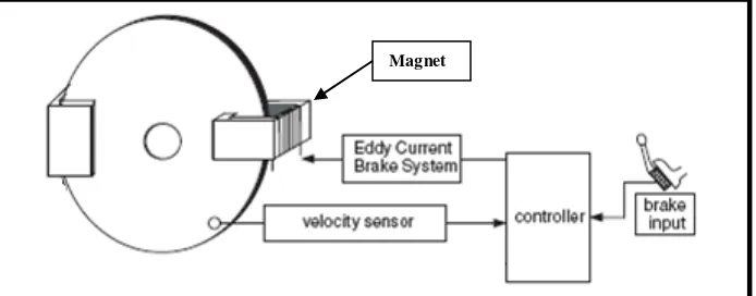
4 HEBS Configuration and Labeling 13
5 Magnetic Brake Work Process 14
6 Ordinary Disc Brake Basic Function and Parts 15
7 HEBS Configuration 16
8 Normal Disc Brake for Car 16
9 Design of Disc Brake and Magnetic Caliper 17
10 Assembly Design of the Magnetic Brake Caliper 17
11 Caliper Parts Assembly 1 18
12 Caliper Parts Assembly 2 18
13 Caliper Parts Assembly 19
14 Solenoid Section 22
15 Solenoid Diagram Inside 22
16 Brake Symbol 23
17 Magnet Basic Principal 23
18 Not Braking Diagram 24
19 Braking Diagram 25
20 Disc Brake Material 25
21 Alternator 32
xiii
LIST OF FIGURE
FIGURE TITLE PAGE
23 Vehicle Model 42
24 Half Car Model 43
25 Vehicle Lateral Dynamic and Yaw Dynamic Model 44
26 Vehicle Longitudinal Dynamic Model 44
27 Wheel Dynamic Model 45
28 Brake Dynamic Model 45
29 Slip Model 46
LIST OF TABLE
TABLE TITLE PAGE
1 Vehicle Specification 26
2 Data Assumption 26
3 Initial Torque Calculation 31
4 Final Calculation and Analysis Result 33
5 Simulation Parameter 41
6 PID Tuning Method 47
7 Tune by Feel for front 48
8 Tune by Feel for rear 48
LIST OF APPENDIX
APPENDIX TITLE PAGE
xv
LIST OF GRAPH
GRAPH TITLE PAGE
1 CARSIM Vx 41
2 ECB on dry asphalt with controller 49
3 CBS on dry asphalt with controller 50
4 HEBS on dry asphalt with controller 50
5 Slip front vs Time 51
6 Vx and ωr front vs Time 51
7 Current front vs Time 52
8 Tb front vs Time 52
9 Slip rear vs Time 53
10 Vx and ωr rear vs Time 53
11 Current rear vs Time 54
LIST OF SYMBOLS
m = Mass (kg)
r = Wheel Radius (m) t = Time (s)
u = Initial Velocity (m/s) v = Velocity (km/h @ m/s)
ax = Longitudinal Acceleration (m/s2) ay = Lateral Acceleration (m/s2) g = Earth Gravity (9.81kgm-2) N = Speed (rpm)
T = Torque (Nm) G = Gear ratio
G T = Transmission Gear ratio
G F = Final Drive Gear ratio
ŊT = Transmission Efficiency
IT = Transmission Inertia (kgm²)
ID = Drive Shaft Inertia (kgm²)
IW = Wheel and Axle Shaft Inertia (kgm²)
IE = Engine Inertia (kgm²)
We = Engine Speed (rads-) WD = Drive Shaft Speed (rads-)
WW = Wheel Speed (rads-)
FX = Tractive force at the ground (N)
xvii
LIST OF SYMBOLS
FD = Aerodynamic Drag force (N)
FHX = Hitch (towing) force (N)
Ft = Frictional Force (N) fr = Rolling Resistance
Ө = Surface Gradient (0) E = Energy (Joule/J) P = Power (Watt/W)
Cσf = Front longitudinal tire stiffness (N/m) Cσr = Rear longitudinal tire stiffness (N/m)
f = Rolling Resistance Coefficient
Iz = Vehicle moment of inertia about yaw axis kgm2 Cαr = Rear axle cornering stiffness (N/rad)
Cαf = Front axle cornering stiffness (N/rad) μ = Coeff.of friction
Ti = Initial Torque (Nm) s = Steer Angle (o)
CHAPTER 1
INTRODUCTION
1.0 Introduction
Brake is a device used to stop or slowing down a vehicle from moving. Brake is a very important component that leads to the safety and protection of the passenger of the vehicle. It is used widely whether on cars, bicycle, airplanes, trucks and other vehicle as well. There are many types of brake such as hydraulic brake, electric brake, and hybrid brake which all of them share the same goal but different shape by their ways and method of operating.
[image:20.612.144.491.539.675.2]The magnetic brake is a brake that uses magnetic as its medium to stop a vehicle from its motion. It uses magnet in its component which differentiate it with other brake. However, the goal is still the same as other brake that is to reduce the speed of vehicle and for the safety of passenger and vehicle.
2
1.1 Scope
• The scope of the project is to design a brake that uses magnetic as its mechanism or medium.
• The brake has to stop a car in a certain speed at a certain distance and time.
• Simulate the behavior of the brake whether the design is successful.
1.2 Objective
The objective of this bachelor project is to train and enhance student ability to use their practical knowledge and experiences in the field of engineering in the relevant undertake to the project. It is to produce students that is capable to develop research method, analysis, design, product production and capable of doing an assessment and evaluation on ones. It is also to train students so that they are able to operate works with minimum valuations and more independent in conducting and producing an academic project and further capable in delivering project work revenue through seminar and written report. As an addition, this project also is for planting and enhances student interest so that they are interested to dabble in the field of research.
The objective of this project is as below:
• To design a magnetic brake for a passenger car.
1.3 Project Problem Statement and Background
4
CHAPTER 2
LITERATURE REVIEW
The literature is information and past studies on the magnetic brake and that are related to it. The literature review for this project is found threw sources from the journal, magazine, articles, books and others.
2.1 Introduction to Brake
2.2 Types of Brakes
2.2.1 Friction Brakes
Friction brakes, the most common kind, operate on the principle that friction can be used to convert the mechanical energy of a moving object into heat energy, which is absorbed by the brake. The essential components of a friction brake are a rotating part, such as a wheel, axle, disk, or brake drum, and a stationary part that is pressed against the rotating part to slow or stop it. The stationary part usually has a lining, called a brake lining, which can generate a great amount of friction yet give long wear; it formerly contained asbestos, but this is being replaced by less efficient materials for environmental reasons.