GRAPHENE – BASED RECTANGULAR MICROSTRIP PATCH ANTENNA USING CST SOFTWARE
MUHD NUR BIN MUKTAR
This Report Is Submitted In Partial Fulfillment of Requirements For The Bachelor Degree of Electronic Engineering (Industrial Electronic)
Fakulti Kejuruteraan Elektronik dan Kejuruteraan Komputer Universiti Teknikal Malaysia Melaka
4 B E N T
UNIVERSTI TEKNIKAL MALAYSIA MELAKA
FAKULTI KEJURUTERAAN ELEKTRONIK DAN KEJURUTERAAN KOMPUTER
BORANG PENGESAHAN STATUS LAPORAN
PROJEK SARJANA MUDA II
Tajuk Projek : ………
Sesi
Pengajian :
Saya ……….. (HURUF BESAR)
mengaku membenarkan Laporan Projek Sarjana Muda ini disimpan di Perpustakaan dengan syarat-syarat kegunaan seperti berikut:
1. Laporan adalah hakmilik Universiti Teknikal Malaysia Melaka.
2. Perpustakaan dibenarkan membuat salinan untuk tujuan pengajian sahaja.
3. Perpustakaan dibenarkan membuat salinan laporan ini sebagai bahan pertukaran antara institusi
pengajian tinggi.
4. Sila tandakan ( √ ) :
SULIT*
*(Mengandungi maklumat yang berdarjah keselamatan atau kepentingan Malaysia seperti yang termaktub di dalam AKTA RAHSIA RASMI 1972)
TERHAD** **(Mengandungi maklumat terhad yang telah ditentukan oleh
organisasi/badan di mana penyelidikan dijalankan)
TIDAK TERHAD
Disahkan oleh:
__________________________ ___________________________________ (TANDATANGAN PENULIS) (COP DAN TANDATANGAN PENYELIA)
Tarikh: ……….. Tarikh: ………..
GRAPHENE-BASED RECTANGULAR MICROSTRIP PATCH ANTENNA BY USING CST SOFTWARE
FKEKK.PSM.0.4
UNIVERSTI TEKNIKAL MALAYSIA MELAKA
FAKULTI KEJURUTERAAN ELEKTRONIK DAN KEJURUTERAAN KOMPUTER
BORANG PENGESAHAN PENERIMAAN LAPORAN PSM II
Nama
Pelajar MUHD NUR BIN MUKTAR
No Matrik B 0 2 1 0 1 0 1 3 5 Kursus 4 B E N T
Tajuk Projek
Saya mengesahkan penerimaan perkara-perkara berikut daripada pelajar seperti yang tercatat di atas:
! 2 Laporan PSM II Berjilid
! 1 Cakera Padat Laporan Akhir
! Hasil Projek (sekiranya berkenaan)
……… ( Tandatangan JKPSM )
Nama &
Cop : ………. Tarikh : ………...
Nota: Bahagian maklumat pelajar mesti ditaip kemas.
iii
“Saya akui laporan ini adalah hasil kerja saya sendiri kecuali ringkasan dan petikan yang tiap-tiap satunya telah saya jelaskan sumbernya.”
iv
“Saya/kami akui bahawa saya telah membaca karya ini pada pandangan saya/kami karya ini adalah memadai dari skop dan
kualiti untuk tujuan penganugerahan Ijazah Sarjana Muda Kejuruteraan Elektronik (Elektronik Telekomunikasi).”
Tandatangan : ………..
Nama Penyelia : AZMAN BIN AWANG TEH
Tarikh : 30 MEI 2014
v
vi
ACKNOWLEDGMENTS
I would like to thank my supervisor, Mr. Azman Bin Awang Teh for all of his supports, guidance and supervision throughout the process to complete and improvement of this thesis.
I also would like to thank Dr. Maisarah Binti Abu and Mdm. Zaharah Binti Manap as my panel for PSM I, and Mdm. Norbayah Binti Yusop and Mdm. Zaharah Binti Manap as my panel for PSM II for their valuable comment about my project during the presentation of PSM I and PSM II. Also thanks to Faculty of Electronic and Computer Engineering (FKEKK) for the provision of resources and facilities during this research process.
I am grateful to all my friends for their encouragement and valuable assistance to accomplish this project.
vii
ABSTRACT
ii viii
ABSTRAK
ix
TABLE OF CONTENTS
CHAPTER SUBJECT PAGE
DEDICATION v
ACKNOWLEDGMENTS vi
ABSTRACT vii
ABSTRAK viii
TABLE OF CONTENTS ix
LIST OF TABLES xiii
LIST OF FIGURES xiv
I PROJECT INTRODUCTION
1.1 OVERVIEW 1
1.2 WAVES ON MICROSTRIP 2
1.2.1 Surface wave 3
1.2.2 Leaky Waves 4
x
1.3 ANTENNA CHARACTERISTICS 6
1.4 OVERVIEW OF GRAPHENE 6
1.5 PROBLEM STATEMENT 7
1.6 AIM AND OBJECTIVES 7
1.7 SCOPE 8
1.8 ORGANIZATION OF THE THESIS 8
II LITERATURE REVIEW
2.1 MICROSTRIP PATCH ANTENNA 9
2.2 ADVANTAGES AND DISADVANTAGES 11
OF MICROSTRIP PATCH ANTENNA
2.3 FEED TECHNIQUES 12
2.3.1 Microstrip Line Feed 13
2.3.2 Coaxial Feed 14
2.3.3 Aperture Coupled Feed 15
2.3.4 Proximity Coupled Feed 16
2.4 METHOD OF ANALYSIS 17
2.4.1 Transmission Line Feed 18
2.4.2 Cavity Model 22
2.5 BASIC PRINCIPLES OF OPERATION 25
2.5.1 Resonant Frequency 25
2.5.2 Radiation Patterns 26
2.5.3 Radiation Efficiency 27
xi
2.6 COPPER-BASED MICROSTRIP 28
PATCH ANTENNA
2.7 GRAPHENE 32
2.7.1 Special Properties of Graphene 33
2.7.2 Graphene vs Copper 34
2.7.3 Application of Graphene 35
2.8 FUNDAMENTAL PARAMETERS OF 36
ANTENNA
2.8.1 Return Loss 36
2.8.2 Realized Gain 36
2.8.3 Efficiency 37
2.8.4 VSWR 37
2.8.5 Directivity 37
III METHODOLOGY
3.1 DESIGN SPECIFICATIONS 38
3.2 DESIGN PROCEDURE 39
3.3 FLOW CHART 42
IV RESULTS AND DISCUSSIONS
4.1 DESIGN PARAMETER 45
4.1.1 Patch Length, L 47
xii
4.1.3 Feeding Length, Lf 49
4.1.4 Feeding Width, Wf 50
4.1.5 Substrate Height, h 50
4.2 OPTIMIZED DESIGN PARAMETER 51
4.2.1 Return Loss (S1,1) 53
4.2.2 Realized Gain 54
4.2.3 Efficiency 55
4.2.4 Voltage Standing Wave Ratio (VSWR) 56
4.2.5 Directivity 57
4.3 OVERALL RESULTS 58
V CONCLUSION AND FUTURE WORK
5.1 CONCLUSION 59
5.2 FUTURE WORK 60
xiii
LIST OF TABLES
NO TITLE PAGE
2.1 Characteristics of different feed techniques 17
2.2 Copper vs Graphene 34
4.1 The parameters of the rectangular Microstrip 46 patch antenna
4.2 Parameter study by using parameter sweep from 46 CST software
xiv
LIST OF FIGURES
NO TITLE PAGE
1.1 Hertz dipole on a microstrip substrate 3
1.2 Surface waves 4
1.3 Leaky waves 5
2.1 Structure of microstrip patch antenna 10
2.2 Common shape of microstrip patch elements 10
2.3 Microstrip Line Feed 13
2.4 Probe fed rectangular microstrip patch antenna 14
2.5 Aperture-coupled Feed 15
2.6 Proximity-coupled Feed 16
2.7 Microstrip Line 18
2.8 Electric Field Lines 18
2.9 Microstrip patch antenna 19
2.10 Top view of the antenna 20
2.11 Side view of the antenna 20
2.12 Charge distribution and current density creation 22 on the microstrip patch
2.13 Electric and magnetic current distribution 26
2.14 Radiation pattern (E & H plane) 28
2.15 Radiation efficiency for a rectangular patch antenna 29 2.16 S-parameter plot for return loss vs frequency 29 2.17 Z-parameter plot for input impedance (Zc) 30
xv
2.19 Elevation pattern for φ = 0 and φ = 90 degrees 31
2.20 Gain vs frequency plot 31
2.21 Graphene with honeycomb structure 33
3.1 Top view of the rectangular microstrip patch antenna 39 3.2 Side view of the rectangular microstrip patch antenna 40 3.3 Simulation of copper-based microstrip patch antenna 41 3.4 Flow chart of designing and simulating the antenna 44
4.1 Parameter sweep of patch length, L 47
4.2 Parameter sweep of patch width, W 48
4.3 Parameter sweep of feeding length, Lf 49
4.4 Parameter sweep of feeding width, Wf 50
4.5 Parameter sweep of substrate height, h 51
4.6 Farfield of copper-based rectangular patch antenna 52 4.7 Farfield of graphene-based rectangular patch antenna 53 4.8 Return loss for both copper and graphene antennas 54 4.9 Clear view of the return loss of both antennas 54 4.10 Realized gain for both copper and graphene antennas 55 4.11 Radiation efficiency and total efficiency for both 55
copper and graphene antennas
CHAPTER I
INTRODUCTION
Communication between humans was first by sound through voice. With the need for slightly more distance communication came, devices such as drums, then, visual methods such as signal flags and smoke signals were used. These optical communication devices, of course, utilized the light portion of the electromagnetic spectrum. It has been only very new in human history that the electromagnetic spectrum, outside the visible region, has been engaged for communication, through the use of radio. One of humankind’s greatest natural supplies is the electromagnetic spectrum and the antenna has been instrumental in harnessing this resource.
1.1 Overview
Microstrip antennas are appealing due to their lightweight, conformability and low expenditure. These antennas can be incorporated with printed strip-line feed networks and active devices. This is a quite new area of antenna engineering.
2 separated by dielectric substrate. This concept was untrained until the revolution in electronic circuit miniaturization and large-scale integration in 1970 [1]. After that many authors have defined the radiation from the ground plane by a dielectric substrate for different configurations.
The early work of Munson on micro strip antennas for use as a low profile flush mounted antennas on rockets and missiles showed that this was a practical concept for use in many antenna system problems. Numerous mathematical models were established for this antenna and its applications were stretched to many other fields. The number of papers, articles published in the journals for the last ten years, on these antennas shows the importance gained by them. The microstrip antennas are the present day antenna designer’s choice.
Low dielectric constant substrates are generally favored for maximum radiation. The conducting patch can take any shape but rectangular and circular configurations are the most frequently used configuration. Other configurations are complex to analyze and require compact numerical computations. A microstrip antenna is characterized by its Length, Width, Input impedance, and Gain and radiation patterns. Numerous parameters of the microstrip antenna and its design considerations were discussed in the subsequent chapters. The length of the antenna is nearly half wavelength in the dielectric; it is a very critical parameter, which governs the resonant frequency of the antenna. There are no hard and fast rules to find the width of the patch.
1.2 Waves on Microstrip
3 Depending on the path toward which waves are transmitted, they fall within three distinct categories, each of which exhibits different behaviours [2].
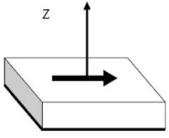
Figure 1.1: Hertz dipole on a microstrip substrate
1.2.1 Surface Waves
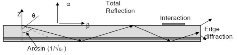
The waves transmitted slightly downward, having elevation angles θbetween
π/2and π - arcsin (1/√εr), meet the ground plane, which reflects them, and then meet the dielectric-to-air boundary, which also reflects them (total reflection condition) [2]. The magnitude of the field amplitudes builds up for some particular incidence angles that leads to the excitation of a discrete set of surface wave modes; which are similar to the modes in metallic waveguide.
The fields remain mostly trapped within the dielectric, decaying exponentially above the interface (Figure 1.2). The vector α, pointing upward, indicates the direction of largest attenuation. The wave propagates horizontally along
β, with little absorption in good quality dielectric [1]. With two directions of αand β orthogonal to each other, the wave is a non-uniform plane wave. Surface waves spread out in cylindrical fashion around the excitation point, with field amplitudes decreasing with distance (r), say1/r, more slowly than space waves. The same guiding mechanism provides propagation within optical fibers.
4 introduce spurious coupling between different circuit or antenna elements. This effect severely degrades the performance of microstrip filters because the parasitic interaction reduces the isolation in the stop bands.
In large periodic phased arrays, the effect of surface wave coupling becomes particularly obnoxious, and the array can neither transmit nor receive when it is pointed at some particular directions (blind spots) [3]. This is due to a resonance phenomenon, when the surface waves excite in synchronism the Floquet modes of the periodic structure.
[image:20.595.115.527.373.470.2]Surface waves reaching the outer boundaries of an open microstrip structure are reflected and diffracted by the edges. The diffracted waves provide an additional contribution to radiation, degrading the antenna pattern by raising the side lobe and the cross polarization levels. Surface wave effects are mostly negative, for circuits and for antennas, so their excitation should be suppressed if possible [2].
Figure 1.2: Surface waves
1.2.2 Leaky Waves
5 This apparent paradox is easily understood by looking at the Figure 1.3, actually, the field amplitude increases as one move away from the substrate because the wave radiates from a point where the signal amplitude is larger. Since the structure is finite, this apparent divergent behaviour can only exist locally, and the wave vanishes abruptly as one crosses the trajectory of the first ray in the figure.
In more complex structures made with several layers of different dielectrics, leaky waves can be used to increase the apparent antenna size and thus provide a larger gain. This occurs for favourable stacking arrangements and at a particular frequency. Conversely, leaky waves are not excited in some other multilayer structures [3].
Figure 1.3: Leaky waves
1.2.3 Guided Waves
When realizing printed circuits, one locally adds a metal layer on top of the substrate, which modifies the geometry, introducing an additional reflecting boundary. Waves directed into the dielectric found under the upper conductor bounce back and forth on the metal boundaries, which form a parallel plate waveguide. The waves in the metallic guide can only occur for some Particular values of the angle of incidence, forming a discrete set of waveguide modes.
The guided waves provide the normal operation of all transmission lines and circuits, in which the electromagnetic fields are generally concentrated in the volume below the upper conductor. On the other hand, this buildup of electromagnetic
6 energy is not suitable for patch antennas, which behave like resonators with a limited frequency bandwidth.
1.3 Antenna Characteristics
An antenna is a device that is made to efficiently emit and receive radiated electromagnetic waves. There are numerous important antenna characteristics that should be measured when choosing an antenna for your application as follows [4]:
i. Antenna radiation patterns ii. Power Gain
iii. Directivity iv. Polarization
1.4 Overview of Graphene
Graphene is come from single layer of carbon atoms that are bonded together in a repeating pattern of hexagons. Graphene is one million times thinner than paper, so thin that it is actually considered as two dimensional, and also the best conductor of electricity known (1x10⁸ S/m) [5].
Carbon is an extraordinarily multipurpose element. Depending on how atoms are prearranged, it can produce hard diamonds or soft graphite. Graphene’s special properties are as follows [6]:
7 2. Graphene is conductive impartial of temperature and works naturally at room
temperature.
3. Strong: As mentioned earlier, it would take an elephant with tremendous balance to break through a sheet of graphene. It is very robust due to its unbroken pattern and the durable bonds between the carbon atoms. Even when patches of graphene are stitched together, it remains the toughest material out there.
4. Flexible: Those tough bonds between graphene’s carbon atoms are also very flexible. They can be distorted, pulled and curved to a certain extent without breaking, which means graphene is stretchable and bendable.
5. Transparent: Graphene absorbs 2.3 percent of the visible light that hits it, which means you can see across the graphene without having to deal with any glare.
1.5 Problem Statement
Microstrip patch antennas are growing in popularity for usage in wireless applications due to their low-profile structure. They are low fabrication charge, hence can be manufactured in huge quantities, and can be simply integrated with microwave integrated circuits (MICs). However, microstrip patch antennas endure from more downsides as compared to conventional antennas such as narrow bandwidth, low efficiency, and low gain.
1.6 Aim and Objectives
8 the effects of copper and graphene as patch materials on antenna gain, return loss, efficiency, VSWR and directivity.
1.7 Scope
Two identical design of rectangular microstrip patch antenna will be done in the CST software. The material in the patch is simulated by using copper and graphene respectively. The antenna will not be fabricated since the graphene is very expensive. The parameters will be varying such as the length of patch (L), width of patch (W), feeding length (Lf), feeding width (Wf), and substrate height (h) of the rectangular microstrip patch antenna design. Then, both of the antenna’s performances are compared in terms of return loss, realized gain, efficiencies, VSWR, and directivity.
1.8 Organization of the Thesis
An introduction to microstrip antenna is given in the Chapter II. Apart from the advantages and disadvantages of the microstrip antenna, the various feeding techniques and models of analysis are listed. The properties of graphene also introduced in this chapter.
Chapter III deals with the antenna parameters and the choice of substrate. The theory of radiation, various parameters and design aspects are discussed. All possible substrates for the design of microstrip antenna with their dielectric constant and permittivity are given.
Chapter IV consists of all the results obtained from both copper-based and graphene-based antenna. The results obtained are stated clearly and also being discussed.