GRAPHENE-BASED NANO PATCH ANTENNA FOR MICROWAVE RADIATION USING CST SOTWARE
HAYATUN HAZIRAH BINTI HAMDAN
This Report Is Submitted In Partial Fulfillment of Requirements For The Bachelor Degree of Electronic Engineering (Wireless Communication)
Fakulti Kejuruteraan Elektronik dan Kejuruteraan Komputer Universiti Teknikal Malaysia Melaka
v
For my beloved father, Hamdan bin Ghazali and my mother, Nor ‘Aisah bt Dusir, For my family and friends who always supports me.
vi
ACKNOWLEDGEMENT
I would like to thank my supervisor, Mr. Azman Bin Awang Teh for all of his support, guidance and supervise throughout the process to complete and improve of this thesis. I
would like to thank PM Dr Zahiril Adha Bin Zakaria and Engr. Norbayah bt Yusop as my panels for PSM I and II for their valuable comment about my project during the
presentation of PSM I and PSM II. Besides, thanks to Faculty of Electronic and Computer Engineering (FKEKK) for the provision of resources and facilities during this
research process. I am grateful to all my friends for their encouragement and valuable assistance to accomplish this project. Lastly, I would like to thanks the most important person in my life, especially my parents, Hamdan Bin Ghazali and Nor ‘Aisah Bt Dusir,
vii
ABSTRACT
viii
ABSTRAK
ix
TABLE OF CONTENTS
CHAPTER SUBJECTS PAGES
PROJECT TITLE i
STATUS REPORT DECLARATION FORM ii
DECLARATION iii
SUPERVISOR DECLARATION iv
DEDICATION v
ACKNOWLEDGMENT vi
ABSTRACT vii
ABSTRAK viii
CONTENT ix
LIST OF TABLES xiii
LIST OF FIGURES xiv
1 PROJECT INTRODUCTION
1.1 OVERVIEW 1
1.1.1 Coplanar Patch Antenna 1
1.1.2 Antenna Characteristics 3
1.1.3 Graphene 4
x
1.2 PROBLEM STATEMENT 5
1.3 AIM AND OBJECTIVES 6
1.4 SCOPES 6
1.5 ORGANIZATION OF THESIS 6
2 LITERATURE REVIEW 8
2.1 COPLANAR PATCH ANTENNA 8
2.2 COPLANAR WAVEGUIDE PATCH 10
ANTENNA
2.2.1 Type of Coplanar Waveguide 10
2.3 METHOD OF ANALYSIS 11
2.3.1 Patch Element Design 11
2.4 FEED/ EXCITATION METHODS 13
2.4.1 Coax Probe Feed 13
2.4.2 Microstrip-Line Feed 13 2.4.3 Proximity-Coupled Feed 14
2.4.4 Aperture-Coupled Feed 14
2.5 GRAPHENE 14
2.5.1 Special Properties of Graphene 15
2.5.2 Graphene VS Copper 16
2.5.3 Graphene Conductivity 16
xi
2.6 BASIC PRINCIPLE OPERATION 18
2.6.1 Resonant Frequency 18
2.6.2 Radiation Pattern 19
2.6.3 Gain 20
2.6.4 Bandwidth 20
2.7 FUNDAMENTAL PARAMETERS OF 21
ANTENNA
2.7.1 Return Loss 21
2.7.2 Realized Gain 22
2.7.3 Efficiency 22
2.7.4 Directivity 22
3 METHODOLOGY 23
3.1 DESIGN SPECIFICATION 23
3.2 DESIGN PROCEDURE 24
3.3 FLOW CHART 27
4 RESULTS AND DISCUSSION 30
4.1 DESIGN PARAMETER 30
4.1.1 Patch Length, L 33
4.1.2 Patch Width, W 34
4.1.3 Feeding Length, Lf 35
xii
4.2 OPTIMIZED DESIGN PARAMETER 37
4.3 GRAPHENE NANO ANTENNA 40
WITH DIFFERENT SHAPE
4.3.1 Shapes of Graphene Nano Antennas 41
4.3.2 Return Loss (S1, 1) 42
4.3.3 Realized Gain 42
4.3.4 Radiation Efficiency 44
4.3.5 Directivity 46
4.4 POTENTIAL INTEREST AND LIMITATION 47 OF USING GRAPHENE AS PATCH
MATERIAL
4.4.1 Potential Interest 47
4.4.2 Limitation 48
4.5 OVERALL RESULT 48
4.5.1 Graphene and Copper as Patch Material 48 4.5.2 Graphene Nano Antenna in Different Shapes 49
5 CONCLUSION AND FUTURE WORK 52
5.1 CONCLUSION 52
5.2 FUTURE WORK 53
xiii
LIST OF TABLES
NO TITLE PAGE
1.1 Type of Metallic Patch Etched on Antenna 5 and its Properties
2.1 Graphene VS Copper 16
4.1 The Parameters of the Coplanar Patch Antenna 31 4.2 Parameter Study by Using Parameter Sweep from 32
CST Software
4.3 The Optimized Design Parameter of the Antenna 37 4.4 Comparison Performance of Antenna by Using Copper 40
and Graphene as Patch Material
4.5 Tabulated Results from the Antenna Parameters 48 (Graphene Vs Copper)
xiv
LIST OF FIGURES
NO TITLE PAGE
1.1 Schematic Diagram of Inset Fed Coplanar Patch 3 Antenna
2.1 A Coplanar Patch Antenna Geometry and Parameter 9 2.2 Common Shape of Patch Antenna Elements 10
2.3 Coplanar Waveguide Cross-Section 11
2.4 Ground Coplanar Waveguide Cross-Section 11 2.5 2D Crystal Honeycomb Lattice of Graphene 15 2.6 Two-dimensional Normalized Field Pattern and 19
Power Pattern
2.7 Return Loss at 2.4 GHz 20
3.1 Top View of Coplanar Patch Antenna 24
3.2 Side View of Coplanar Patch Antenna 25
3.3 Simulation Design of Graphene-Based Coplanar 27 Patch Antenna
3.4 Flow Chart of Designing and Simulating the Antenna 29 4.1 Return Loss (S1, 1) at 12 GHz for Initial Parameter 31
4.2 Parameter Sweep of Patch Length, L 33
4.3 Parameter Sweep of Patch Width, W 34
4.4 Parameter Sweep of Feeding Length, Lf 35 4.5 Parameter Sweep of Thickness of Graphene, Tg 36 4.6 Return Loss (S1,1) For Copper-based Coplanar 38
xv
4.7 Return Loss (S1,1) For Graphene-based Coplanar 38 Nano-Patch Antenna
4.8 Farfields For Copper-based Coplanar Nano-Patch Antenna 38 4.9 Farfields For Graphene-based Coplanar Nano-Patch Antenna 39 4.10 Comparison of Return Loss (S1, 1) by Using Graphene 40
and Copper as Patch Material
4.11 Graphene Nano Antennas in Different Shape 41 4.12 Return Loss (S1, 1) for the Different Antenna Shapes 42 4.13 Realized Gain for Rectangular Patch Antenna 43 4.14 Realized Gain for Diamond Patch Antenna 43 4.15 Realized Gain for Elliptical Patch Antenna 44 4.16 Radiation Efficiency for Rectangular Patch Antenna 45 4.17 Radiation Efficiency for Diamond Patch Antenna 45 4.18 Radiation Efficiency for Elliptical Patch Antenna 45 4.19 Comparison of Directivity of Different Antenna Shapes 46
at 12 GHz
1
CHAPTER I
INTRODUCTION
Antenna and antenna systems are the eyes and ears of wireless communication systems, which experienced an unprecedented rapid expansion. The wireless systems, no matter how simple or complex, cannot operate efficiently unless they utilize transmitting and receiving elements or antennas to efficiently radiate and receive the waves that carry the information. The future of the communication systems is even more challenging, and their efficacy will depend on what engineers and scientist can invent and contribute. In fact, some of the future services and performances of wireless communication may be dependent on and limited antenna design which will require our imagination and vision to push the outer limits of the laws of physics.
1.1 Overview
1.1.1 Coplanar Patch Antenna
2
scale integration in the earlier 70’s, demand for compact antenna with small size, which can be integrated with MMIC designs increased. Since planar antennas are substrate based antennas and their properties like ease in fabrication, and easy integration with MMIC and PCB designs, increased popularity of planar antenna and influenced large number of research in this field. Planar patch antenna have advantages like low profile, lightweight and ease fabrication. Microstrip patch antenna is the most popular of all the other type of planar antennas. It consists of grounded substrate with conducting patch above the substrate. But they have certain disadvantages too like low gain, narrow bandwidth and low efficiency [2]. Coplanar patch antenna is new and better alternative of microstrip patch antenna. A coplanar patch antenna has ground and patch on the same side of the substrate with a gap width. Since the effective dielectric constant for a coplanar antenna design is lower than microstrip antenna design, the surface wave excitation is reduced to a large extent and due to the reason coplanar antenna have high radiation efficiency and wider bandwidth. Also, coplanar patch antennas easy to fabricate, have low radiation loss, less dispersion, uniplanar configuration and easy MEMS based reconfigurable antennas can be designed without using via holes as used in case of microstrip design.
3
Figure 1.1: Schematic Diagram of Inset Fed Coplanar Patch Antenna
1.1.2 Antenna Characteristics
An antenna is a critical device in wireless communication system that provide a means of radiating and receiving waves. It will ease all the electromagnetic waves that it receive in to free space wave. There are numerous important antenna characteristics that should be measured when choosing an antenna for your application as follows [3]:
4
1.1.3 Graphene
Graphene is a flat monolayer of carbon atom tightly packed into 2D honeycomb lattice. The layer of graphene stacked on top of each other form graphite. Graphene had been isolated in 2004 by two Russian-born researcher at University of Manchester, Andre Grim and Kostya Novoselov [8]. Graphene is ultralight, strongest material, superb conductor and thinnest material in the world. Graphene’s special properties are as follows [14]:
1. Conductivity: Electrons are the particles that make up electricity. So when graphene permits electrons to move rapidly, it is allowing electricity to move speedily. It is known to move 200 times faster than silicon because they travel with such slight interruption. It is also an excellent heat conductor. Graphene conductive impartial of temperature and works naturally at room temperature. 2. Strong: It would take an elephant with tremendous balance to break through a sheet of graphene. It is very robust due to its unbroken pattern and the durable bonds between the carbon atoms. Even when patches of graphene are stitched together, it remains the toughest material out there.
3. Flexible: These tough bonds between graphene’s carbon atoms are also very flexible. They can be distorted, pulled and curved to a certain extent without breaking, which means graphene is stretchable and bendable.
4. Transparent: Graphene absorbs 2.3 percent of the visible light that hits it, which means you can see across the graphene without having deal with any glare.
5
[image:20.612.114.540.129.487.2]1.1.4 Type of Metallic Patch Etched on Antenna
Table 1.1: Type of Metallic Patch Etched on Antenna and its Properties [14]
Copper SWCNT MWCNT Graphene
Conductivity(s/m) 5.96 x 10⁷[5] 102[6,7] 105[7,8] 108[9,10]
Melting point (K) 1356 3800 (graphite)
Tensile strength
(GPa)
0.22 22.2+2.2 11-63
Thermal
conductivity (x
10-3W/m-K)
0.385 1.75-5.8 3 3-5
Temp. Coeff. Of
resistance (x 10
-3/K)
4 <1.1 -1.37 -1.47
Mean Free path
@ room
temperature
40 103 2.5 x 10⁴ 103
Maximum
Current Density
(A/cm2)
107 109 109 108
1.2 Problem Statement
6
of graphene in passive guide devices and antennas from microwave to THz have been far less exploited.
1.3 Aim and Objectives
The aim of the thesis is to design graphene-based nano-pach antenna operating at microwave frequency (8-16GHz), identify the effect of changing the shape of graphene patch towards the antenna efficiency and to analyze the potential interest and limitation of using graphene in microwave frequency for antenna application.
1.4 Scope
A design of a coplanar graphene-based nano-patch antenna will be done in the CST software. The material in the patch is simulated only by using graphene. The antenna will not be fabricated since the graphene is very expensive and due to the lack of technology to handle graphene. The frequency range use to simulate the design is around 8 GHz to 16 GHz. The parameter will be varying such as the value of length of graphene (L), width of graphene (W), thickness of graphene (Tg) and shape of graphene patch. Then, the antenna’s performances are compares in terms of gain, return loss and radiation efficiency.
1.5 Organization of the Thesis
An introduction to coplanar patch antenna is given in the Chapter II. Apart from the advantages and disadvantages of coplanar patch antenna, the various models of analysis are listed. The properties of graphene also introduced in this chapter.
7
Chapter IV consists of all the results obtained from different varieties of parameters of graphene-based nano-patch antenna. The results obtained are stated clearly and also being discussed.
8
CHAPTER II
LITERATURE REVIEW
A patch antenna (also called as a rectangular microstrip antenna) is a type of radio antenna with a low profile, which can be attached on a flat surface. It consist of metallic patch etched on a dielectric substrate which has a grounded metallic plane at the opposite side. Differed from patch antenna, coplanar patch antenna consist of metallic patch and grounded plane etched on the same side. Coplanar patch antenna are simple to fabricate and easy to transform and customize.
2.1 Coplanar Patch Antenna
9
[image:24.612.238.468.220.370.2]The coplanar patch antenna has advantages, compared with the microstrip antenna, such as easier to connect with active devices, providing a unidirectional radiation pattern, and so on [25]. Introducing the concept of coplanar patch also makes easy to employ the various techniques developed for microstrip patch antennas in the development of many kinds of new coplanar patch antennas.
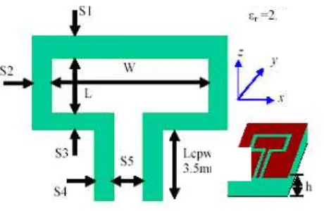
Figure 2.1: A Coplanar Patch Antenna Geometry and Parameter
![Table 1.1: Type of Metallic Patch Etched on Antenna and its Properties [14]](https://thumb-ap.123doks.com/thumbv2/123dok/485167.53248/20.612.114.540.129.487/table-type-metallic-patch-etched-antenna-properties.webp)