i
UNIVERSITI TEKNIKAL MALAYSIA MELAKA
STUDY ON WEAR RATE OF TiAlN BALL NOSE DURING
MILLING INCONEL 718 UNDER FLOODED LUBRICATION
This report submitted in accordance with requirement of the Universiti Teknikal Malaysia Melaka (UTeM) for the Bachelor Degree of Manufacturing Engineering
(Manufacturing Process) (Hons.)
by
NURUL NADIA BINTI MUHAMMAD RAFIE EMPARI B051110044
920216-06-5236
ii
DECLARATION
I hereby, declare this report entitled “STUDY ON WEAR RATE OF TiAlN BALL NOSE DURING MILLING INCONEL 718 UNDER FLOODED LUBRICATION”
is the results of my own research except as cited in the reference.
Signature : ……….
Author Name : ………
Date : ………
iii
APPROVAL
This report is submitted to the Faculty of Manufacturing Engineering of UTeM as a partial fulfillment of the requirements for the degree of Bachelor of Manufacturing Engineering (Process) (Hons.). The member of the supervisory is as follow:
i
ABSTRAK
ii
ABSTRACT
iii
DEDICATION
For my beloved family:
Muhammad Rafie Empari Bin Abdullah
Salina Binti Razali
Mazlan bin Razali
Nurul Najwa Binti Muhammad Rafie Empari
Muhammad Mustaqim Bin Muhammad Rafie Empari
And
iv
ACKNOWLEDGEMENT
Bismillahirrahmanirrahim. With the name of Allah the most Gracious and the most Merciful.
I would like to express my utmost appreciation to my final year project supervisor Dr. Mohd Shahir Bin Kasim for his guidance during the whole duration of Projek Sarjana Muda (PSM). The supervision and support that he gave truly help the progression and smoothness of completing my final year project. He also always gives advices and motivates me to work harder and smarter.
Besides, I would like to thank Assistant Engineer of FKP‟s CNC lab, En. Mohd Hanafiah bin Mohd Isa for his help during completing my final year project.
Above all, I heartily thankful to my parents, Muhammad Rafie Empari bin Abdullah and Salina binti Razali, my siblings; Nurul Najwa and Muhammad Mustaqim and my uncle who raised me up, Mazlan bin Razali for their continuous support and encouragement. They made me agree that verily with every hardship, there is relief.
v
TABLE OF CONTENT
Page
Abstrak i
Abstract ii
Dedication iii
Acknowledgement iv
Table of Content v
List of Tables viii
Lists of Figures ix
List of Abbreviation, Symbols and Nomenclature xi
1.0 CHAPTER 1: INTRODUCTION
1.1 Project Background 1
1.2 Problem Statement 3
1.3 Objectives 4
1.4 Scope 5
1.5 The Organization of Report Dissertation 5
2.0 CHAPTER 2: LITERATURE REVIEW
2.1 Introduction 7
2.1.1 Fundamental of Milling Process 9
2.1.2 Performance Evaluation of Milling Process 10 2.1.3 Effect of Cutting Speed on Tool Life 10
2.1.4 High Speed Machining 11
vi
2.3 Inconel 718 15
2.3.1 Machinability of Inconel 718 17
2.4 Equipment Tool Material 19
2.4.1 Coated Carbide Tool 19
2.4.2 Titanium Aluminium Nitride (TiAlN) 20
2.4.3 Tool Geometry 20
2.5 Lubrication 21
2.6 Design of Experiment (DOE) 21
2.6.1 Response Surface Methodology (RSM) 22
2.6.2 ANOVA Analysis 23
3.0 CHAPTER 3: RESEARCH METHODOLOGY
3.1 Introduction 24
3.2 Experimental Setup 27
3.2.1 Machine Tool 27
3.2.2 Workpiece Material 29
3.3 Equipments 30
3.3.1 Tool Maker Microscope 30
3.4 CNC Machine 31
3.5 Preparation for Machining Test 32
3.5.1 Machining parameter 32
3.5.2 Machining Procedure 35
3.6 Criteria in Determining the Tool Wear 37
3.7 RSM Analysis 38
3.7.1 Box- Behnken 39
vii
4.0 CHAPTER 4: RESULTS AND DISCUSSION
4.1 Introduction 41
4.2 Wear Rate of Inconel 718 42
4.2.1 Type of Model for Variance Analysis 44 4.2.2 Analysis of Variance (ANOVA) Wear Rate using RSM 45 4.2.3 Development of Mathematical Model of Wear Rate
(TiAlN) ball nose
46
4.2.4 Model Validation from ANOVA 48
4.3 Influence of Machining Parameters on Wear Rate 51
4.3.1 One Factor Plot (Feed Rate) 51
4.3.2 Interaction Graph (Depth of Cut and Cutting Speed) 52
4.4 Optimization of Machining Parameters 55
4.4.1 Optimization of Wear Rate 56
4.5 Failure Modes During Machining Inconel 718 58 4.6 Comparison of wear rate between MQL and Flooded Conditions 60
4.7 Sustainable Development 62
5.0 CHAPTER 5:CONCLUSIONS AND RECOMMENDATIONS
5.1 Conclusion 63
5.2 Recommendations 64
REFERENCES 65
viii
LIST OF TABLES
2.1 Chemical Composition of each types of Inconel 718 (Li, Zeng et al. 2006; Aviation Metals Inc. 2011).
15
2.2 Properties of Inconel 718 (Xue, Lijun et al. 2003). 16 3.1 Criteria of TiAlN (Sumitomo Electric Hardmetal 2010) 27 3.2 Chemical Composition of Inconel 718 718 (Jawaid, Koksal et al.
2001)
30
3.3 Research Machining Parameters 32
3.4 Cutting Speed, Vc 33
3.5 Feed Rate, fz 33
3.6 Depth of Cut, ap 34
3.7 Research Parameters from Box-Behnken 34
3.8 Three-factor Box- Behnken design 39
4.1 Wear Rate of Ball Nose (TiAlN) during end milling Inconel 718 42
4.2 Sequential Model Sum of Squares 44
4.3 Variance analysis for Wear Rate of TiAlN ball nose 45 4.4 Error between Mathematical model and Experimental Results 47 4.5 Combination of Random Cutting Parameters and Predicted
Result for Validation
50
4.6 Target Criteria to Obtain Optimum Machining Parameters 54
4.7 Suggested Solutions of Parameters 55
ix
LIST OF FIGURES
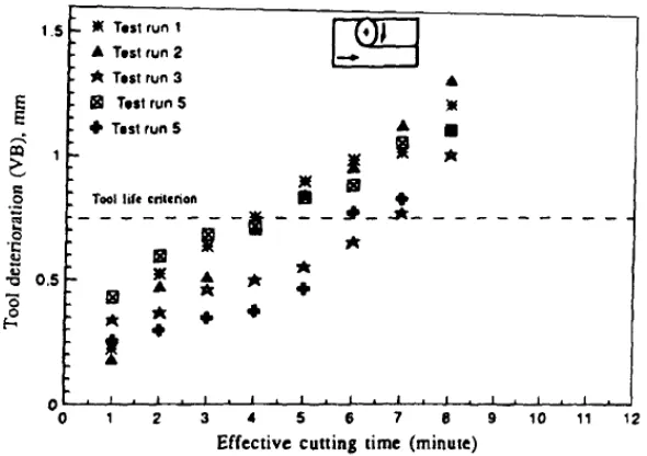
1.1 Tool deterioration (flank wear) values of end mill 4
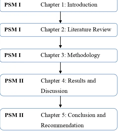
1.2 Report Organization 6
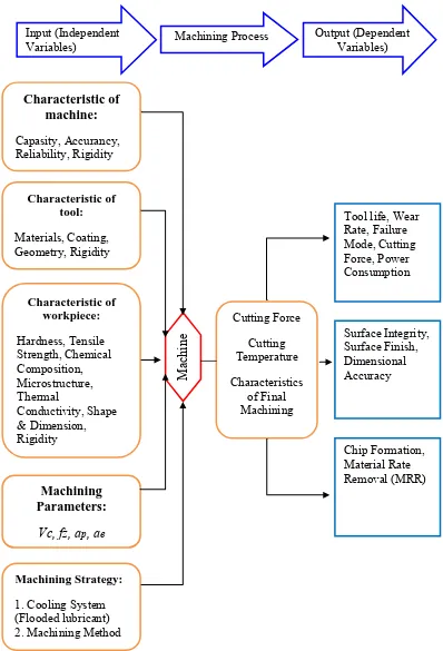
2.1 Relationship between independent and dependent variables to machining output.
8
2.2 Flank Wear vs Cutting Time at Various Cutting Speed. 11 2.3 The range for cutting speed according to machining process
and type of materials.
12
2.4 The causes of tool failure. 13
2.5 The relationship between temperature °C of Inconel 718 and Vickers Hardness.
18
2.6 Disadvantages of non-coated tools. 19
3.1 Flowchart of Research 25
3.6 The position of specimen during wear measurement 31
3.7 3-Axis CNC Machine, FKP, UTeM 32
3.8 Minimum tangential force exerted at the cutting tool 34
3.9 G-code generated 36
x
4.1 Wear Rate (mm/min) from the experiments 43
4.2 Actual Values vs Predicted Values of Wear Rate of TiAlN
(mm/min) 48
4.3 Normal Plots of Residuals 49
4.4 (a) Cook‟s Distance 49
4.4 (b) Predicted vs Actual 49
4.5 Wear Rate Generated during Machining Inconel 718 50
4.6 (a) Influence of feed rate on wear rate 51
4.6 (b) Influence of depth of cut and cutting speed on wear rate 52 4.6 (c) Influence of depth of cut on wear rate at different cutting
speed
53
4.6 (d) Effect of ap on wear rate at different cutting speed 54 4.7 Minimum Wear Rate Achieved from the Combination of Each
Parameter 57
xi
LIST OF ABBREVIATIONS, SYMBOLS AND
NOMENCLATURE
ISO - International Standard Organization
MDI - Manual Data Input
Mn - Manganese
Mo - Molybdenum
xii MRR - Material rate removal
Nb - Niobium
Ni - Nickel
O2 - Oxygen
PCBN - Polycrystalline cubic boron nitride PhD - Doctor of Philosophy
PVD - Physical vapour deposition
Ra - Surface roughness
RSM - Response Surface Methodology
Si - Silicone
T - Tool Travel
Ti - Titanium
TiAlN - Titanium Aluminium Nitride TiN - Titanium Nitride
VB1 - Flank wear
VB3 - Non-uniform flank wear
Vc - Cutting speed
Vceff - Effective cutting speed
WC - Tungsten carbide
1
CHAPTER 1
INTRODUCTION
1.1 Project Background
End milling is one of the materials removing process that widely used in manufacturing engineering component (Kalpakjian & Schmid, 2003). This process is one of the final processes in the production especially to produce high precision of mechanical products. In aerospace industry, the demand of complex shape, high accuracy and high better surface finish require for application of ball nose compare to other shapes of cutting tools (Alauddin, El Baradie, & Hashmi, 1995). Due to these scenarios, many researchers and as well as manufacturers conduct an ongoing research to meet the quality standards required.
2 Most of the problem arise during machining Inconel reported was flank wear, notch wear, crater wear (Jawaid, Che-Haron, & Abdullah, 1999). The increasing of these wear deteriorated cutting tool that will change cutting geometry. Moreover, the formation of build up edge (BUE) worsening cutting performance by increasing of flaking formation and notch wear (Liao & Shiue, 1996). The formation of these unpredictable problems lead to premature tool failure (Kasim et al., 2014).
The development of coating technology improves durability of cutting tool (Graham, 2008). During initial stage of study in 1980s, most of researchers used coated carbide rather than uncoated carbide (Trent & Wright, 2000). Taking advantage of development of coating technology, most of investigation done using coated carbide. Lee et al. (2009) done by using PVD, Krain et al. (2007) done using CVD and Koshy et al. (2002) using PCBN. However due to cost constrain, coated carbide was become more popular in market that contribute of 80-85% of market share (Krain, et al., 2007).
One of the strategies done to increase tool performance is by implementing high speed machining (HSM). HSM generally associated with end milling at rotational speed at 100,000 rpm (Ng, Lee, Dewes, & Aspinwall, 2000; Sharman, Dewes, & Aspinwall, 2001b). It was proven that the tool life can be prolong up to 7 min (Alauddin, et al., 1995).
3
1.2 Problem Statement
During the machining process, any changes in the shape of machining tool will directly influence the machining efficiency. Specifically, Inconel 718 possesses high strength, work hardening and dynamic shear strength at room and elevated temperatures (Bouzakis, Aichouh, & Efstathiou, 2003). However, due to metallurgical and mechanical characteristics leads to highly valued properties which also make them one of the most difficult to machine aerospace material (Bhatt, Attia, Vargas, & Thomson, 2010b).
It maintains high strength at temperatures typically encountered during cutting leading to high cutting forces and high temperatures in the shear zone which causes plastic deformation of the cutting tool edge (Krain, et al., 2007). Rapid tool wear in machining has long been recognised as a challenging problem in this industry (H. Z. Li, et al., 2006).
The tool will work efficiently in its original geometry. For milling process, the critical limit for tool life when the flank wears below 0.3 mm (Jawaid, Koksal, & Sharif, 2001). Normally, flank wear beyond this amount will affect cutting performance. The cutting force will increase as the tool geometry deteriorates (Ng, et al., 2000). This is mainly caused by the tool wear and fracture failures of the tool during the machining process (Childs, Maekawa, Obikawa, & Yamane, 2000). Apart from tool lifetime, the replacement cost of a worn tool (consumable cost) and time to replace a worn-out tool are important in machining economics.
Previous research by Alauddin et al. (1995) found that the tool life is not instigated. The tool life is only about 7 min at Vc = 19.32 m/min, fz = 0.091 mm/tooth, ap = 1.00mm. The result is shown in the Figure 1.1. Meanwhile Krain et
4
Figure 1.1: Tool Deterioration (Flank Wear) Values of End Mill (Alauddin, et al., 1995)
1.3 Objectives
During cutting operation, the changes on the shape of the cutting tool will affect the effectiveness of the cutting tool itself. To understand this scenario, a research on the workpiece and cutting parameters are required.
1. To study the effect of machining parameters on the wear rate of ball nose TiAlN during end milling of Inconel 718 under flooded lubrication.
2. To develop a mathematical model to predict wear rate by using Response Surface Methodology (RSM) analysis.
5
1.4 Scope
This research will investigate the tool performance by observing wear rate of ball nose end milling. The coated carbide insert with Titanium Aluminium Nitride (TiAlN) will be used during experiment process using 3 axis CNC milling machine. The material to be used is Inconel 718. Under this research, there are 3 machining parameters that being considered namely; cutting speed (Vc), feed rate (fz) and depth
of cut (ap). Meanwhile, width of cut (ae) is a fixed variable in this research. Response
Surface Methodology (RSM) will be used as a statistical tool of design of experiment.
1.5 The Organization of Report Dissertation
This report consists of 5 chapters:
a) The first chapter describes in general about the research background and problem statement that leads to this research. Experimental objectives and scope of the research also indicated in this chapter.
b) The second chapter includes a review of previous scientific studies on machining Inconel 718. It consists of a variety failure mode and tool wear mechanisms that occur during the cutting process of this material. In addition, the application of flooded lubricant, experimental designs and data analysis, Response Surface Methodology (RSM) with Box-Behnken approach are also discussed in this chapter.
6 d) The fourth chapter discusses in detail regarding the result obtained from the experiment regarding the tool wear. The results are shown in the form of graphs and supported by statistical data through analysis if variance (ANOVA) method. A mathematical model will be developed and compared with the results. Some of the results will be evaluated and compared with previous researcher, Kasim (2014) through his PhD thesis titled „The Performance of Coated Carbide Cutting Tool during End Milling of Inconel 718 in a Minimum Quantity Lubricant (MQL)‟. Analysis if the data regarding the tool wear is briefly discussed in this chapter.
e) The last chapter, Chapter 5, discusses the conclusion of the research and suggestions for future research.
Figure 1.2 shows the report organization for PSM I and PSM II.
Figure 1.2: Report Organization
PSM I Chapter 1: Introduction
PSM I Chapter 2: Literature Review
PSM I Chapter 3: Methodology
PSM II Chapter 4: Results and Discussion
7
CHAPTER 2
LITERATURE REVIEW
This chapter discusses on the related information, previous researchers‟ findings and the current knowledge regarding this topic.
2.1 Introduction
Machining operation is the core of the manufacturing industry since the industrial revolution. Machining is a process which a raw material undergoes a material-removal process in order to get its desired shape and size by using the selected tool and machine. The manufacturers are trying to produce the maximum quantity of product through a minimum production cost and at the same time meet its quality standards (Rao, 2011).
8
Figure 2.1: Relationship Between Independent and Dependent Variables to Machining Output (Alauddin, El Baradie, & Hashmi, 1996; Rao, 2011).
Machining Process
Variables) Output (Dependent Variables)
9 2.1.1 Fundamental of Milling Process
Milling is consider as multi tooth cutting process, the process differs with turning and grinding where the process is a single cutting tool and random cutting tool respectively (Kalpakjian & Schmid, 2003). However, some milling process uses a single cutting tool, especially for experiment purpose (Richetti, Machado, Da Silva, Ezugwu, & Bonney, 2004).
Previous researchers‟ opinions said that the cuts happened upon the formation of metallic fragments during metal-removing process. It occurs as there is plastic deformation on the workpiece caused by the opposite movement between the tool and the workpiece (Childs, et al., 2000). In addition, this metal cutting is different from the concept of cutting blade when cutting a soft material whereby a wedge-shaped tool is forced symmetrically into the material (Trent & Wright, 2000).
When the tool is in contact with the workpiece, it requires more force to overcome the opposite force from the workpiece. At an early stage, the accumulated force will cause deformation on the worpiece and push it out towards the surface of the tool which is known as chips. Such high and uniform force will cause shearing and tearing on the workpiece which eventually will push the workpiece until a chip is formed (Schrader & Elshennawy, 2000).