REMOTELY OPERATED CONSTRUCTION ROBOT TELE-OPERATION COMMAND AND CONTROL SYSTEM
AQMAL HISYAM BIN HAMZAH
SUPERVISOR DECLARATION
“I hereby declare that I have read this thesis and in my opinion this thesis is sufficient in terms of scope and quality for the award of the degree of
Bachelor of Mechanical Engineering (Thermal Fluid)”
Signature : ………
Supervisor : Dr. Ahmad Anas Bin Yusof
REMOTELY OPERATED CONTRUCTION ROBOT TELE-OPERATION COMMAND AND CONTROL SYSTEM
AQMAL HISYAM BIN HAMZAH
This thesis is submitted to Faculty of Mechanical Engineering in partial fulfillment of the requirement for the award of Bachelor’s Degree in
Mechanical Engineering (Thermal Fluid)
Faculty of Mechanical Engineering Universiti Teknikal Malaysia Melaka
DECLARATION
“I hereby declare that the work in this thesis is my own except for summaries and quotations which have been duly acknowledged.”
Signature : ………
Author : Aqmal Hisyam Bin Hamzah
ACKNOWLEDGEMENT
In the name of Allah, thank God and praise to Him the Almighty in his will author can complete this Final Year Project at Universiti Teknikal Malaysia Melaka. A lot of knowledge that I received during last year in completing final year project and I indebted to who had made this final year project successful achieve the objective. A lot of deepest gratitude to my supervisor Dr Ahmad Anas Bin Yusof that continuous supporting and guiding me in knowledge and asset during this semester.
ABSTRACT
ABSTRAK
TABLES OF CONTENTS
CHAPTER TITLE PAGE
DECLARATION ii
ACKNOWLEDGEMENT iii
ABSTRACT iv
ABSTRAK v
TABLES OF CONTENTS vi
LIST OF FIGURE ix
LIST OF ABBREVIATIONS xi
1 INTRODUCTION 1
1.0 Introduction 1
1.1 Background 1
1.2 Objective 3
1.3 Scope 3
1.4 Problem Statement 3
2 LITERATURE REVIEW 4
2.0 Introduction to Tele-operated Vehicle 4
2.1 Construction Vehicle 5
2.2.1 Excavator as Construction Vehicle. 5
2.2.2 Excavator Component 6
2.2 Control System of Tele-operated Mechanism 13
2.3 Bilateral Tele-operation System 15
2.4.1 Mini Excavator Hydraulic Arm as a Slave
System 17
2.4.2 Joystick Force Feedback with Master
System 18
2.5 Coordinate System Control 19
2.6 Arduino Software as Control System 20
2.7 Programmable Logic Controller (PLC) System 23
3 METHODOLOGY 24
3.0 Introduction 24
3.1 Research Method 24
3.2 Master Slave Control System Construction 26
3.2.1 Kobelco Hydraulic Excavator 26
3.2.2 Controller Computer System 27
3.2.3 SolidWorks Software as Design Platform 27
3.2.4 Arduino program and SKPS Wireless
Transmitter as Control System 28
3.3 Development of Command and Control
System of Mini-Excavator 29
3.3.1 Development of Demo-kit Design 30
3.3.2 Development of Remote-Controlled System 33
3.3.3 Use of Arduino Tool for ‘Sketches’ 33
4 RESULT AND ANALYSIS 39
4.0 Introduction 39
4.1 Fabrication of Demo-Kit 39
4.2 Remote Controller Work Mechanism 47
4.3 Development of PS2 Controller Coding Logarithm 47
4.4 Development of Main Processing Code 51
4.5 Result 58
5 DISCUSSION 59
5.1 Fabrication Problem of Demo-Kit 59
5.2 Insufficient Amount of Component 63
5.3 Hardware Connection 64
6 CONCLUSION 66
6.0 Conclusion 66
6.1 Recommendation 67
REFERENCES 68
LIST OF FIGURE
NO TITLE PAGE
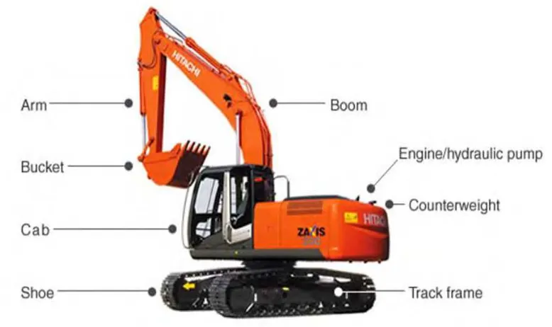
2.1 Component of excavator 6
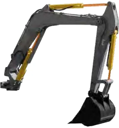
2.2 Sample of excavator arm 7
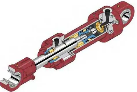
2.3 Sample of excavator hydraulic cylinder with
cross-sectional view 8
2.4 Sample of exactor swing 9
2.5 Sample of excavator cab inside view 10
2.6 Sample of excavator level control pattern 10
2.7 Sample of crawler feet excavator 11
2.8 Sample of excavator boom 11
2.9 Diesel engine use in excavator 12
2.10 Sample of bilateral block diagram 13
2.11 Multilateral tele-operation system 14
2.12 Typical tele-operation system 15
2.13 The bilateral tele-operation control system 16
2.14 Schematic diagram of virtual reality-based construction
tele-robot control 17
2.15 Main component of hydraulic arm 17
2.16 Block diagram of fine motion and gross motion 18
2.17 Coordinate system that use on excavator 19
2.18 Four degree of Freedom of hydraulic system 20
2.19 The structure of a tele-controlled for hydraulic excavator 21
2.20 Sample of Arduino tool to make ‘Sketches’ 22
2.21 Sample of Arduino board 22
2.22 Components arrangement of a PLC 23
3.2 Kobelco hydraulic excavator 26
3.3 Sample of main SolidWorks user interface 27
3.4 Arduino Uno board 28
3.5 The SKPSW wireless module 29
3.6 The operational lever on excavator 30
3.7 Drawing of Air Cylinder CM2 Series 31
3.8 Hardware compartment 31
3.9 Hydraulic compartment 31
3.10 Six cylinder and compartment fitted together 32
3.11 Hydraulic and hardware compartment attached together 32
3.12 Failed at installing driver software 34
3.13 Device manager 34
3.14 Update Driver Software 35
3.15 Arduino IDE 35
3.16 Arduino software interface 36
3.17 Sketches or Coding of ‘Blink Without Delay’ 36
3.18 Arduino Board is chosen 37
3.19 ‘Blink Without Delay’ circuit 37
4.1 Hydraulic and hardware compartment attached together 40
4.2 Untidy wiring for the Demo-Kit 41
4.3 Both fabricated compartments 41
4.4 Swan Air Compressor 42
4.5 Hardware cover drawing 43
4.6 Pneumatic cover drawing 44
4.7 Fabrication defect 45
4.8 Modification to compartment 45
4.9 Hardware and pneumatic compartment 46
4.10 Using bracket as defect solution 46
4.11 Analog joystick 47
4.12 The remote controller are successfully move the cylinder 58
5.1 Pneumatic cylinder series XA 20-100-S 60
5.2 Measurement inside SolidWorks 60
5.4 Digital calliper 61
5.5 Smart scope 62
5.6 Tightener nut 64
5.7 Crowded wire 64
LIST OF ABBREVIATIONS
TEODOR = Telerob Explosive Ordnance Disposal and Observation
Robot
ROV = Remotely Operated Vehicle
DOF = Degree of Freedom
LAN = Local Area Network
IDE = Integrated Development Environment
GPS = Global Positioning System
LCD = Liquid Crystal Displays
PLC = Programmable Logic Controller
IEC = International Electro technical Commission
DAC = Digital to Analog Converter
USB = Universal Serial Bus
PC = Personal Computer
USB = Universal Serial Bus
LED = Light Emitting Diode
LIST OF APPENDIX
NO TITLE PAGE
CHAPTER 1
INTRODUCTION
1.0 INTRODUCTION
This study covers on the development of a remote-controlled system for operated construction robot tele-operation using command and control system. This chapter will be focusing on the background of construction robot tele-operation, objective, scopes and the initial problem detection during this study.
1.1 BACKGROUND
and the most sophisticated is using robot for planets exploration. People who have lost arms and legs have implementing robotic technology to gain their life back.
Remote controlled robot is another perfect robotic mechanism in order to get the hand to hand feel between the user and robot. A robot that equipped with a remote controlled mechanism solely focusses on using during dangerous situation to humans such as fire rescue, hurricanes disaster, explosions and deep sea exploration that requires the more expert individuals to be at the specific location which in this case is human.
For example a remote-controlled, heavy-duty robot TEODOR (Telerob Explosive Ordnance Disposal and Observation Robot) is designed and manufactured by Telerob, a business unit of Cobham Unmanned Systems. This robot is capable in enhanced bomb disposal situations and been used by Explosive Ordnance Disposal (EOD) teams. The robot that been controlled by human using remote controlled have high reliability and exceptional manoeuvrability. The robot can identify and disarm booby traps, fireworks, improvised explosives devices and other dangerous objects in closed areas, buildings and vehicles. It also can perform surveillance, investigations and monitoring of object in abnormally dangerous conditions. The TEODOR bomb disposal robot system have been work together with military and law enforcement unit of more than 41 countries worldwide (Kable., 2014)
1.2 OBJECTIVE
The research aims is in developing a command and control system for controlling a mini excavator from afar using a remote control mechanism that have been programmed using Arduino Programming. The goal of this research is to develop ways to program a controller connection in order to move hydraulic actuator that uses to control the movement of levers on top of the mini excavator.
1.3 SCOPE
The scope of this research is to develop a coding logarithm using Arduino Programming in order to move the mini excavator. By implementing Arduino Programming, another scope of this research is to move and control the excavator arm using a remote command and control system.
1.4 PROBLEM STATEMENT
CHAPTER 2
LITERATURE REVIEW
2.0 INTRODUCTION TO TELE-OPERATED VEHICLE
Tele operation means simply to operate a vehicle or a system over a distance. Distance can vary form tens of centimetres or in micro manipulation to millions of kilometres which exceed for space applications. Tele operation as a part of robotics has a long and rich history. Nowadays many fields of science and economy, such as medicine, industry, nuclear power stations and army. Tele operation have evolved into more complex and integrating more robots adaptations, mechanisms, control systems and many other devices. These are the reasons that distribution of control signals between such multiple tele operation signals is important and compelling (Farkhatdinov, I. and Ryu, J.H., 2008).
multi-object system. Intelligence of humans plays significant role in control of multiple-object systems.
Human’s intelligence and skills can be used in tele operation system in order to certificate safety and high quality of robotic system. In making decisions during tele operation of several object quickly, humans solely rely upon high intelligence and well developed sensory system. It is important to design friendly and intuitive human-robot interface in order to make the remote control easier (Farkhatdinov, I. and Ryu, J.H., 2008).
For this research, tele operation concept have been implemented in means to control a mini excavator. Mini excavator used in this research is a type of construction vehicle that is used in isolated and small areas of project. This mini excavator can be used only by one individual. The person who in charge controlling the excavator must use the lever on top of the excavator to move the direction of the arm and also the excavator itself.
2.1 CONSTRUCTION VEHICLE
According to Occupational Health and Safety Act, 1993 under the code of Construction Regulation, 2003, “Construction vehicle” means a vehicle that been used for means of conveyance for transporting persons or material or both such persons and material, as the case may be, both on and off the construction site for the purposes of performing construction work. Particularly, construction vehicle is design for carrying out heavy duty construction such as soil operations, heavy lifting, and also use during as emergency. It is usually known as heavy machines, heavy trucks, engineering equipment, construction equipment, heavy hydraulics or heavy vehicles.
2.2.1 Excavator as Construction Vehicle.
production in heavy construction equipment have been covered by these excavators. And will be expected that the percentage of excavators in industrial site will be increased (Moon, S. M. et al., 2009).
[image:22.595.137.526.299.530.2]An excavator uses hydraulics or a wire rope pulley system to dig holes or trenches and is, therefore, of the called a digger. Bobcats and backhoes are also called excavators. An excavators has a long boom arm and a cab that is mounted on a pivot. The boom is connected at an elbow to a stick that holds the bucket. Attachment of the ‘bucket’ can be replaced with different attachment depending on the condition of the job site. The cab can pivot in a full circle. Because 360 degree rotation is available, another name for an excavator is a 360 digger (Kevin, F. and Stonecypher, L., 2009).
Figure 2.1: Component of excavator (Source: Hitachi contsruction machinery, 2010)
2.2.2 Excavator Component
swing 360 degree without any interruption. The excavator engine main function is to drive the hydraulic pumps that provide oil at a high pressure to the slew motor, rams, track motors, and several accessories. Usually, the boom can move only up and down, or in addition also shift towards the left and right of the machine. The boom end is attached with an arm that imparts the force for digging into the ground. At the arm end, a bucket is attached for carrying the soil. Additionally, there are numerous other categories of attachments with the excavator that are used for boring, crushing, lifting, and ripping (Orfano, F. and Swagatam, 2009).
[image:23.595.210.411.457.673.2]An excavator arm can be equipped with a couple of hydraulic cylinder, this type of excavator usually known as a hydraulic excavator. A hydraulic arm consist of a bucket and a boom. Hydraulic cylinder in excavator arm usually located on top of the arm. A boom is where the transaction of energy between the hydraulic onto the bucket happen. The actual excavator arms is moving like a parts human hand movement that move on the wrist and the elbow. Figure 2.2 below shows a sample of excavator arm (Source: Open source ecology, 2013)
Other main parts of an excavator is hydraulic cylinder. Hydraulic cylinders is used to move the arm of the excavator, it work by extracting energy from the fluid and convert it to mechanical energy to perform useful work. Hydraulic cylinders are also called linear actuators can extend and retract a piston rod to provide a push or pull force to drive the external load along a straight-line path. In an excavator, a hydraulic cylinder are used to drive the boom which attached and connect to the bucket part (Esposito, A. 2009). Inside a hydraulic cylinder it consist of a rod and a piston, the piston is positioned by the end of the cylinder and also act to prevent the oil to leak. Higher pressure of oil in the cylinder will allow the piston rode to move the arms of the excavator (Haga et al., 2001). The simplest type of hydraulic cylinder is the single-acting cylinder. It consist of a piston inside a cylindrical housing called a barrel. Attached to one end of the piston is a rod, which extends outside one end of the cylinder. At the other end is a port for the entrance and exit of oil. Different from hydraulic cylinder used in excavator, it uses the mechanism of double-acting cylinder. Double-acting cylinder can be extended and retracted hydraulically. Thus, an output force can be applied in two directions which is extension and retraction (Esposito, A. 2009). Figure 2.3 shows a sample of hydraulic cylinder (Flemings, 2012).
Figure 2.3: Sample of excavator hydraulic cylinder with cross-sectional view (Source: Flemings, 2012)