ISSN: 1992-8645 www.jatit.org E-ISSN: 1817-3195
AN OPTIMAL TUNING OF PSS USING AIS ALGORITHM
FOR DAMPING OSCILLATION OF MULTI-MACHINE
POWER SYSTEM
1RAMADONI SYAHPUTRA, 2INDAH SOESANTI
1
Department of Electrical Engineering, Faculty of Engineering, Universitas Muhammadiyah Yogyakarta
Jl. Ringroad Barat Tamantirto, Kasihan, Yogyakarta, INDONESIA
2
Department of Electrical Engineering and Information Technology, Faculty of Engineering, Universitas Gadjah Mada, Yogyakarta, INDONESIA
E-mail: [email protected]; [email protected], [email protected]
ABSTRACT
This paper proposes an optimal tuning of Power System Stabilizer (PSS) using Artificial Immune System (AIS) algorithm for damping oscillation of multi-machine power system. PSS is the efficient devices to damp the power system oscillations which are caused by interruptions. This study presents a robust algorithm to determine the PSS parameters using AIS algorithm. The PSS parameters tuning is usually formulated as the objective function with constraints, including the damping ratio and damping factor. Optimization with maximum value of the damping factor and the damping ratio of power system modes are taken as the goals functions, when designing the PSS parameters. This optimization procedure could enhance the cloning process and lead to a better outcome. In this work, the two-area multi-machine power system of IEEE model, under a wide range of system configurations and operation conditions is investigated. The system has been used to illustrate the performance of the proposed algorithm. The performance of the AIS-based PSS is compared to the Delta w PSS and Delta Pa PSS. The results verify that, AIS-based PSS, Delta w PSS and Delta Pa PSS gives relatively good in reducing oscillation system variables of which transfer electrical power, changes in angular velocity generator, and the generator terminal voltage. All PSS can work well in order to stabilize the system under interruption. However, AIS-based PSS have relatively better than Delta w PSS and Delta Pa PSS in terms of ability to reduce oscillation and speed of reaching a state of instability.
Keywords: Power System Stabilizer (PSS), Artificial Immune System (AIS) Algorithm, Optimal Tuning,
Transient Stability, Damping Oscillation, Multi-Machine Power System.
1. INTRODUCTION
Power system stabilizer (PSS) is a device that used to mitigate system damping of low-frequency oscillations is an important control objective for optimization design in electrical power systems. The conventional tuning processes based on the linear approaches such as the eigenvalue analysis, for the linear parameters of the PSS tuning such as gain and time constants, have been used. Electrical power systems are often operated in situations of critical that may lead to instability cases and in worst-case blackouts [1]-[4]. In many of electric power systems around the world, the large interruptions have historically occurred [5]-[8]. This condition may lead to panic and state of emergency in the society, something to be avoided [9]-[10]. However, by focusing only on small signal
ISSN: 1992-8645 www.jatit.org E-ISSN: 1817-3195 system is defined as the ability of the system to
maintain the synchronization at the time of both interruption and after interruption occurs [13]-[15].
Increasing in intricacy of electric power systems has enhanced interests in developing the methodologies for PSS [16]-[18]. The effects of both transient and dynamic stability are among the main issues in the reliable and efficient operation of power systems. Low frequency oscillation modes have been observed when the multi-machine power systems are interconnected by weak tie-lines. The mode is also called the mode of electromechanical oscillation, and it usually happens in the frequency range of 0.1 to 2 Hz.
PSS is the most efficient device for damping both local mode and inter-area mode small signal low frequency oscillation by increasing the system damping. In large power system, the machines are equipped with PSS, which provides supplementary feedback and stabilizes the signal in the excitation system. The problem of PSS design is to tune the parameters of the stabilizer. The problem can cause the increase of damping of the system’s electromechanical oscillation modes. The tune of PSS must be done without adverse effects on other oscillatory modes, such as those associated with the exciters or the shaft torsional oscillations. The PSS must also be so designed, that it has no adverse power systems. PSS action is to expand the limits of the stability of bulk multi-machine power system by delivering synchronous machine rotor oscillation damping via the excitation generator [19]. Oscillation damping is provided by an electric torque applied to the rotor in line with variations of speed. On the other hand, the use of artificial intelligence (AI)-based algorithm has a lot of help in the field of bulk power systems [20]-[24]. The use of artificial intelligence (AI)-based algorithm is not only limited to the field of image processing [25]-[29]. In the last two decades, various methods have been applied to create design of PSS in order to improve the performance of the bulk power system. Most of the PSS model which is used in the power system was developed based on the classical linear control theory [30]-[31]. The linear control refers to a linear model of the power system configuration that is fixed value. Therefore, the PSS with fixed parameters are often called the
traditional PSS. The traditional PSS is able to function at its optimum for a particular operating condition in constant. The PSS is not effective for the operating conditions change drastically [32]-[39]. Therefore, in this study will be elaborated models of artificial immune system based technique for PSS tuning model in order to overcome the problem of transient stability of the multi-machine electrical power system. In this approach, it is conducted linearized model of the machines on interconnected electric power system. By this technique, it is expected to be obtained by a relatively simple method and suitable for overall electrical power system conditions that are various greatly.
2. POWER SYSTEM STABILIZER IN
ELECTRICAL POWER SYSTEM
2.1. Power System Stabilizer Model
In bulk electrical power system, it is generally consists of a multi-machine system connected to an infinite bus. Growing in both generation and load of power system, the more vulnerable to interference, especially short-circuit interference. One effect of the interference is the oscillation of power that will cause the system out of the area of stability. It can also result in an even worse as a total blackout. The occurrence of short circuit faults in transmission line for the various types that is to disruption by 70% for one phase to ground fault, two-phase to ground fault by 10%, phase to phase fault by 15%, and symmetrical three-phase fault by 5%.
Stability of power system is characterized into both steady state and transient stabilities. Transient stability associated with the major interruption that occurs suddenly, like a short circuit faults, line disconnections, and removal or disconnection of the burden. On the other hand, the steady state stability associated with the ability of the power system to return to the conditions of its operating point after a small disturbance or rejection such as changes in power or load smoothly. The stability is also called dynamic stability. Small changes in load will result in a change in the angular velocity of the machine rotor, resulting change in terminal voltage of the machine. The angular velocity of the synchronous machine will swing around speed and voltage terminal converging around its rating voltage.
ISSN: 1992-8645 www.jatit.org E-ISSN: 1817-3195 system is called “unstable”. Due to changes in the
load on dynamic stability studies are relatively smalls, the multi-machine system model used in this study is a linearization of non-linear models. Small change in load on the system is a matter that could not be avoided and it is always the case. It is necessary to design a controller of power system that can maintain the system remains stable, commonly called Power System Stabilizer (PSS).
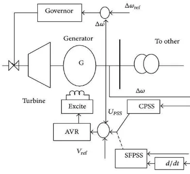
Figure 1. Typical structure of PSS
Figure 2. Typical Structure Of Ieee Type St1 Excitation System With Pss
The general function of a PSS is to generate appropriate torque on the machine rotor, in such a way that, the phase lag between the exciter input and the machine electrical torque is compensated. In many study, the extensively used speed based PSS design is considered where the stabilizing signal is assumed to be proportional to the speed perturbation. The typical structure of PSS is shown in Figure 1. It consists of a gain block with gain Ki, a signal washout block and two-stage phase compensation blocks.
Another type of PSS is shown in Figure 2. A PSS is placed with each synchronous generator. The PSS is used to provide an additional damping torque if system tempts to become unstable for oscillations. All PSSs are traditional PSS which consists of two-stage lead-lag compensation blocks with one gain and one washout block. The input of PSS is rotor speed deviation (Δω). Figure 2 shos the
IEEE type ST1 excitation system with PSS. In the figure, Tw is the washout time constant. Tw is set to 10 s for all PSSs. The parameters which are optimized consist of lead-lag time constants (T1, T2,
T3, and T4) and gain constant (K). Figure 3 shows
block diagram of PSS in a control system.
Figure 3. Block diagram of PSS in a control system
Figure 4. Position Of Pss In A Power Plant
The basic function of PSS is to expand the limits of stability by modulating the excitation machine to produce oscillation damping rotor synchronous machine. The oscillation of power is usually occurs within a frequency range of about 0.2 to 3.0 Hz. The oscillation can interfere with the rotor power frequency. The ability of the power system to transmit electrical power can be deteriorated. For damping these oscillations, PSS must be able to produce electric torque according to the changes of rotor speed. One example of the position of PSS in a power plant in addressing the stability of the power system is shown in Figure 4.
ISSN: 1992-8645 www.jatit.org E-ISSN: 1817-3195 2.2. Artificial Immune System Method
Artificial immune system (AIS) concept is used to explain the basic response of the immune system by being adaptive to antigen stimulation. The concept is described in Figure 5. This concept states that the only cells able to recognize antigens that will proliferate and the other cells are ignored. In the concept of AIS, the clonal selection operates on B cells and T cells in cell B, when the antibody binds to the antigen then activated and differentiated into plasma cells or memory cells. With respect to this process, B cell clones are produced and undergo somatic hyper-mutation. As the results, the diversity in the population of B cells to plasma cells produce antibodies antigen-specific works against antigens is obtained. As the consequence, the memory cells be left over with host antigens and promote secondary response quickly.
The important features of the artificial immune system type of clonal selection are:
a. new cells are duplicates of those parents (called “clone”) which is charged with the rapid mutation mechanism height (somatic hyper-mutation),
b. the elimination of the new different lymphocyte causing it the self-reactive receptors,
c. the proliferation and the differentiation takes place through connection adult cells with antigen, and
d. the persistence of illegal clones, resistant to early elimination by self-antigen, is used as the basis of the auto-immune disease.
Fig. 5. The Principle Of Artificial Immune System
The analogy with selection of naturally fit the reality that is the strongest candidate into most cells recognizes antigens or into cells most triggered. To
workings of this method, repertoire or population of receptors should be diverse enough to recognize any form of foreign cells. The immune system of a mammalian contains a heterogeneous repertoire of about 1012 lymphocytes in humans, and the rest of B cells (stimulated) can display about 105-107 identical like-antibody receptor. If the repertoire has been believed complete, it means that he can recognize the shape of any cell.
In [11], they have presented the algorithm of clonal selection, called “ClonalG” for optimization process. They proposed the important features of the concept of clonal selection and develop algorithms include the maintenance of a set of specific memory, selection and cloning antibodies are most stimulated, death antibody non-excitatory, maturation affinity. After that, the selection of re-clones is balanced against affinity antigen, and the generation and maintenance of a set of antibodies.
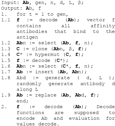
The important steps of artificial immune system type of clonal selection are described below.
Input: Ab, gen, n, d, L, β; randomly generate antibody d along L
The affinity between antigen and antibody can be defined using different methods such as matching rules and a measure of distance. One common method used is the Euclidean distance. The method is suitable when using a real-valued vector representation. In order to explain the work of ClonalG using Euclidean distance, suppose Ag = {Ag1, Ag2, ..., AgN}, and Ab = {Ab1, Ab2, ..., AbN}
ISSN: 1992-8645 www.jatit.org E-ISSN: 1817-3195 based on the distance of Euclidean:
(
)
And then, d compared with the threshold λ, and a matching error E is obtained using the equation:
E = d – λ
(2)If E > 0, it is considered that the two vectors do not match, so that these antigens are not recognized by the antibody while if E <= 0, concluded that Ag Ab match, then the antigen recognized by the antibody. The common range for calculation of affinity is varying between 0 and 1.
For maturation of affinity, algorithm of ClonalG assumes that the n highest affinity antibody is sorted rise, and the number of clones that are raised for all n selected antibodies, which are given by:
∑
with N is the clones total number for each antigen, β are the cloned factor determining the scale factor for the clones number for antibodies elected and β second highest yield of 100 clones, and thus further [11]. specifically designed to study low frequency electromechanical oscillations in large interconnected multi-machine electrical power systems. In the IEEE model, there are four synchronous which are interconnected in a system. Although the size of the system created in this study
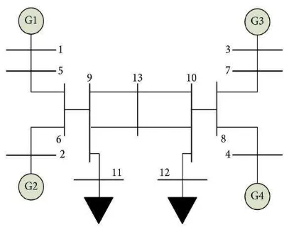
was relatively small, but already represents multi-machine system in actual operation. The IEEE multi-machine power system circuit diagram model in this study is shown in Figure 6. The IEEE standard multi-machine power system consists of 4 generators and 13 buses by interference on the transmission line.
Figure 6. IEEE Model Multi-Machine Power System Of 4 Generators And 13 Buses By Interconnection On The
Transmission Line
ISSN: 1992-8645 www.jatit.org E-ISSN: 1817-3195
Figure 7. A Two Area Multi-Machine Power System Under Study
ISSN: 1992-8645 www.jatit.org E-ISSN: 1817-3195
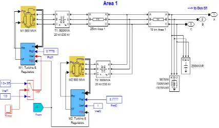
Figure 9. Configuration Of Area 2 Of Multi-Machine Power System
ISSN: 1992-8645 www.jatit.org E-ISSN: 1817-3195 The IEEE model of multi-machine power
system in this study is shown in Figure 7. It can be seen in Figure 7 that the multi-machine power system has two areas which is interconnected by the transmission lines. Figure 8 shows the configuration of multi-machine power system components of area 1 while Figure 9 shows configuration of components of area 2 of IEEE model multi-machine power system under study.
In the IEEE model of multi-machine power system under study, the load of the system is represented as constant impedances and split between the two areas. The area 1 is exporting 413MW to area 2. The multi-machine system is somewhat stressed, even in steady-state, because the surge impedance loading of a single line is 140 MW. The reference power flow with generator M2 considered the slack machine is such that all generators are producing the active power about 700 MW. In this work, the power losses of transmission and generation may vary depending on the detail level in power transmission line and generator parameter representation.
4. RESULTS AND DISCUSSION
4.1 Multi-machine Power System Analysis for Small Signal
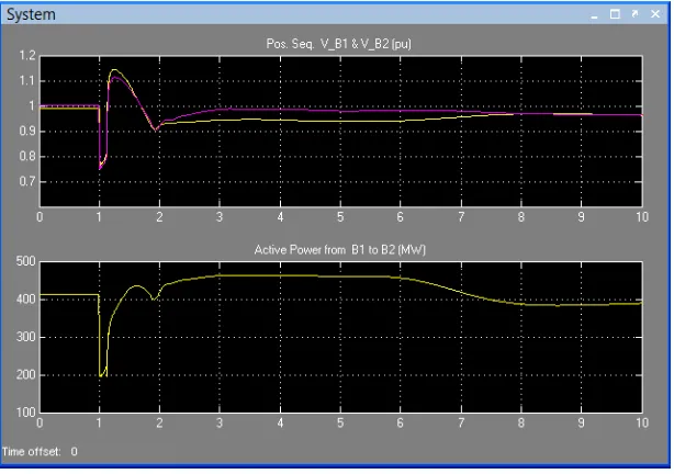
In this work, an IEEE model of multi-machine power system analysis for small signal is examined. In order to comprehend the behavior of the network, the open-loop responses to a magnitude pulse of 5% is applied for 12 cycles at the generator M1 voltage reference. By using the simulink toolbox, simulation is started by opening the timer controlling the generator M1 voltage reference and changing the factor of multiplication of the transition time vector from 100 to 1. After that, the power transmission line fault should be deactivated by changing from 1 to 100 the factor of multi-plication of the transition time vector in the fault device and transmission line breakers. And then, the signals responses are visualized by opening the scopes of "Machine" and "System" on the main diagram as shown in Figure 7.
Figure 11. The Signals Of The System Scope Under Simulation In Simulink
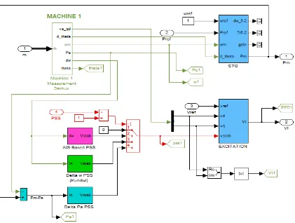
Figure 10 shows the PSS model with AIS-based method in machine 1 of area 1 of multi-machine power system under study. The PSS model with AIS-based is compared with another PSS model, i.e. Delta w PSS and Delta Pa PSS. As input data for both PSS model with AIS-based method and Delta w PSS is the same, namely a change in
ISSN: 1992-8645 www.jatit.org E-ISSN: 1817-3195 can be seen in Figure 11 and Figure 12, all signals
show undamped oscillations leading to unstable. A modal analysis of acceleration powers of all generators shows the three dominant modes, i.e.:
a. Mode of interarea (fn = 0.66Hz , z = -0.028) involving the whole area 1 against area 2. This mode is clearly observable in the tie-line power displayed in scope of "System".
b. Area 1 using local mode (fn = 1.14Hz, z = 0.09) involving this area's machines against each other.
c. Area 2 using local mode (fn = 1.17Hz, z = 0.09) involving generator M3 against
generator M4 (in this case, the smaller the
inertia then the greater the frequency of local natural).
From Figure 8 and Figure 9, if the circuit breakers both Brk1 and Brk2 are setting in the
position of open circuit, then one of the two tie-lines of the circuit is removed. Figure 8 shows the configuration of all component of area 1 of multi-machine power system while Figure 9 shows the
configuration of all component of area 2 of multi-machine power system. Each area has the two synchronous machines with the capacity of 900 MVA. Each of the machine is equipped with the 20/230 kV power transformer with the capacity of 900 MVA. It is possible to reach the point of steady-state stable equilibrium with the same patterns of load and power generation. This phenomenon is named a post-contingency network. The post-contingency network can be initialized using the Machine and Load-Flow Initialization toolbox in simulink software feature. After that, analysis in modal type for the network's responses to the same 5% of magnitude pulse could be done. By the analysis, it can be understood that it was applied for 12 cycles at the voltage reference of generator M1 reveals that. Therefore, at this time
the two local modes has been remain basically unchanged in both natural frequency and damping factor, i.e. fn=1.10Hz, z=0.09 in area 1, and fn=1.18Hz, z=0.09 in area 2. And then, the interarea mode will shift to a lower frequency with unstable condition, i.e. fn = 0.45Hz and z = -0.017.
ISSN: 1992-8645 www.jatit.org E-ISSN: 1817-3195 4.2 Tuning of AIS-based PSS for Multi-machine
Power System
In this study, the AIS-based PSS setting is created in matlab m-file, and then the file is connected to the PSS model in simulink environmental. In order to examine the AIS-based which is proposed in this work, it has been simulated another PSS scheme, i.e. delta w PSS and delta Pa PSS, as shown in Figure 10. The results of bode plot of all PSS scheme in this work is shown in Figure 13. For the Delta w PSS, the setting data are from Kundur [18]. The Delta w PSS settings have two changes i.e. a gain increase from 25 to 30 and a 15-ms transducer time constant. The frequency responses of all the three PSS in this simulation can be seen on Bode Plot of all PSS in Figure 13. Based on the the figure, it can be seen that the AIS-based PSS, which is proposed in this
study, is effectively flat around 25-40 degrees in the frequency range of interest. As a comparison, Delta w PSS has an overall poor phase shape, especially around the frequency of 1-2 Hz. By this fact, there makes it unable to cope with faster local or inter-machine modes in multi-unit power system. Thus, for Delta Pa PSS, it has a good performance in combination of strong gain and phase advance above frequency of 0.3 Hz. However, the Delta Pa PSS type is unpractical at low frequency. From bode plot diagram, it shows a 180 degrees phase advance, which actually has a destabilizing effect despite the rather small low-frequency gain. For the third PSS scheme, Delta w PSS, the low-frequency shaping is satisfactory in overall, but its DC rejection is not efficient enough. This frequency condition is providing five times less attenuation than the proposed AIS-based PSS.
10-2 10-1 100 101 102 0
20 40 60 80 100 120 140 160
p
u
/p
u
PSS Frequency Response
10-2 10-1 100 101 102 -200
-100 0 100 200
D
e
g
re
e
s
Frequency (Hz) Delta Pa converted to
Delta w PSS ( = Delta Pa * 2Hs)
AIS-Based PSS
Conventional Delta w (from Kundur) Equivalent Delta Pa
ISSN: 1992-8645 www.jatit.org E-ISSN: 1817-3195 4.3 Small-Signal Performance Assessment of
AIS-based PSS
In this part, the small-signal performance assessment of AIS-based PSS is explained. In order to examine the small-signal with closed-loop system responses of the PSS, the transition time vector of circuit breakers and all fault devices on the main diagram should be disabled by multiplying it by 100. After that, the timer block is used to example terminal voltage and generator speed, are stored in matrices W and Vt. It can be seen inside both blocks of Machines and System on the main diagram for other variables. This procedure can be repeated for the all the three PSSs for performance comparison. In order to examine the comparisons, it can be done by double clicking on icon Show
results: Step on vref of generator M1. The
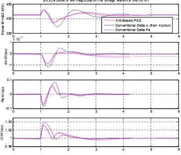
simulation results of this part are show in 12-cycle pulse of 5% of voltage reference magnitude of generator M1, as presented in Figure 14. The figure have four plots, i.e. the top one shows the power transfer from area 1 to area 2, the second one is the generator M1 speed, the third one is acceleration
) 12-cycle pulse of 5% magnitude on the voltage reference (vref) of M1
0 1 2 3 4 5 6
ISSN: 1992-8645 www.jatit.org E-ISSN: 1817-3195
8-cycle three-phase fault with the outage of one 230kV line
0 5 10 15
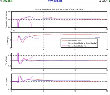
Figure 15. 8-Cycle Symmetrical Three Phase Fault With The Outage Of 30 Kv Transmission Line
Figure 14 shows four variables of 12-cycle pulse of 5% of voltage reference magnitude of generator M1, i.e. power transfer from area 1 to area 2,
angular velocity change, power of generator M1,
and terminal voltage of generator M1, respectively.
In Figure 14, it can be seen that all PSSs have a nice in stabilizing the naturally unstable system. However, if compared with another to PSS, the AIS-based PSS is superior. The AIS-based PSS provides significantly more damping to all modes, especially with respect to the Delta w PSS. The Delta w PSS is poor gain shaping above frequency of 0.5 Hz while the proposed AIS-based PSS have good performance. For overall, the damping performance of the interarea-mode with two ties of multi-machine power system for all PSS is: AIS-based PSS: fn = 0.4Hz and z = 0.35; Delta w PSS: fn = 0.64Hz and z = 0.25; Delta Pa PSS: fn = 0.35Hz and z = 0.30. For damping performance of the interarea-mode with two ties multi-machine power system for all PSS is: AIS-based PSS: fn =
0.42Hz and z = 0.37; Delta w PSS: fn = 0.43Hz and z = 0.35; Delta Pa PSS: fn = 0.23Hz and z = 0.14.
4.4 Large-Signal Performance Assessment of AIS-based PSS
In this part, the large-signal performance assessment of all PSS model is explained. In order to assess the proposed AIS-based PSS, small-signal performance is not enough. Therefore, the large-signal performance is needed. Figure 15 shows 8-cycle three phase fault with the outage of 230 kV power transmission line. The robust performance during large perturbations is one of the criteria of PSS characteristic assessment. Another criterion of an equal importance is good robustness with respect to changing operating conditions. The system response to a symmetrical three-phase fault cleared in 8 cycles by opening both the breaker Brk1 and
Brk2 can be simulated by using the same procedure
ISSN: 1992-8645 www.jatit.org E-ISSN: 1817-3195 condition of without one tie-line. By the simulation,
not every PSS is able to ensure a smooth transition into this new highly stressed operating point.
Figure 15 shows four variables 8-cycle symmetrical three phase fault with the outage of 30 kV transmission line, i.e. power transfer from area 1 to area 2, angular velocity change, power of generator M1, and terminal voltage of generator M1,
respectively. From figure 15, it can be seen that for implementation of Delta Pa PSS, the system lost its synchronism while both AIS-based PSS and Delta oscillation frequency of the AIS-based is lower. For Delta w PSS, it is too slow on recovering the terminal voltage. In addition, the acceleration of power is more damped with the proposed AIS-based PSS model than any other PSS, as can be seen in Figure 15. It is an advantage of the proposed AIS-base PSS compared to the two others PSS.
5. CONCLUSION
In our research, AIS-based PSS has been successful in controlling the multi-machine power system under study. Multi-machine power system consists of four generators. Application testing on the generator M1 to symmetrical three-phase short circuit fault, it is resulted that the proposed AIS-based PSS have good design in this study. All PSS in this study, i.e. AIS-based PSS, Delta w PSS and Delta Pa PSS, have given relatively good results in reducing oscillation system variables of which transfer electrical power, changes in angular velocity generator, and generator terminal voltage. However, the performance of the proposed AIS-based PSS have relatively better than Delta w PSS and Delta Pa PSS in terms of ability to damp oscillation and speed of reaching a stability state. Based on this study, it can be seen that the proposed AIS-based PSS rapidly deliver good results compared with Delta w PSS and Delta Pa PSS primarily on the state of the multi-machine power system.
ACKNOWLEDGMENT
The authors gratefully acknowledge the contributions of the Ministry of Research,
Technology and Higher Education, Republic of Indonesia, for funding this research.
REFRENCES
[1] Syahputra, R., Soesanti, I., Ashari, M. (2016). Performance Enhancement of Distribution Network with DG Integration Using Modified PSO Algorithm. Journal of Electrical Systems (JES), 12(1), pp. 1-19.
[2] Syahputra, R., Robandi, I., Ashari, M. (2014). Optimization of Distribution Network Configuration with Integration of Distributed Energy Resources Using Extended Fuzzy Multi-objective Method. International Review of Electrical Engineering (IREE), 9(3), pp. 629-639.
[3] Syahputra, R., (2012), “Distributed Generation: State of the Arts dalam Penyediaan Energi Listrik”, LP3M UMY, Yogyakarta, 2012. [4] Syahputra, R., (2016), “Transmisi dan
Distribusi Tenaga Listrik”, LP3M UMY, Yogyakarta, 2016.
[5] Syahputra, R., (2015), “Teknologi dan Aplikasi Elektromagnetik”, LP3M UMY, Yogyakarta, 2016.
[6] Syahputra, R., (2012), “Fuzzy Multi-Objective Approach for the Improvement of Distribution Network Efficiency by Considering DG”, International Journal of Computer Science & Information Technology (IJCSIT), Vol. 4, No. 2, pp. 57-68.
[7] Syahputra, R., Robandi, I., Ashari, M. (2014).
“Optimal Distribution Network
Reconfiguration with Penetration of Distributed Energy Resources”, Proceeding of 2014 1st International Conference on Information Technology, Computer, and Electrical Engineering (ICITACEE) 2014, UNDIP Semarang, pp. 388 - 393.
[8] Syahputra, R., Robandi, I., Ashari, M. (2015). Performance Improvement of Radial Distribution Network with Distributed Generation Integration Using Extended Particle Swarm Optimization Algorithm. International Review of Electrical Engineering (IREE), 10(2). pp. 293-304.
ISSN: 1992-8645 www.jatit.org E-ISSN: 1817-3195 [10]Syahputra, R., Robandi, I., Ashari, M. (2015).
PSO Based Multi-objective Optimization for Reconfiguration of Radial Distribution Network. International Journal of Applied Engineering Research (IJAER), 10(6), pp. 14573-14586.
[11]Syahputra, R., Robandi, I., Ashari, M., (2012), “Reconfiguration of Distribution Network with DG Using Fuzzy Multi-objective Method”, International Conference on Innovation, Management and Technology Research (ICIMTR), May 21-22, 2012, Melacca, Malaysia.
[12]Utomo, A.T., Syahputra, R., Iswanto, (2011), “Implementasi Mikrokontroller Sebagai Pengukur Suhu Delapan Ruangan”, Jurnal Teknologi, 4(2).
[13]Syahputra, R., Robandi, I., Ashari, M., (2011), “Modeling and Simulation of Wind Energy Conversion System in Distributed Generation Units”. International Seminar on Applied Technology, Science and Arts (APTECS). 2011; pp. 290-296.
[14]Syahputra, R., Robandi, I., Ashari, M., (2011), “Control of Doubly-Fed Induction Generator in Distributed Generation Units Using Adaptive Neuro-Fuzzy Approach”. International Seminar on Applied Technology, Science and Arts (APTECS). 2011; pp. 493-501.
[15]Jamal, A., Syahputra, R., (2011), “Design of Power System Stabilizer Based on Adaptive Neuro-Fuzzy Method”. International Seminar on Applied Technology, Science and Arts (APTECS). 2011; pp. 14-21.
[16]Jamal, A., Syahputra, R. (2012), “Adaptive Neuro-Fuzzy Approach for the Power System Stabilizer Model in Multi-machine Power System”, International Journal of Electrical & Computer Sciences (IJECS), Vol. 12, No. 2, 2012.
[17]Jamal, A., Syahputra, R. (2011), “Model Power System Stabilizer Berbasis Neuro-Fuzzy Adaptif”, Semesta Teknika, Vol. 14, No. 2, 2011, pp. 139-149.
[18]Jamal, A., Suripto, S., Syahputra, R. (2015). Multi-Band Power System Stabilizer Model for Power Flow Optimization in Order to Improve Power System Stability. Journal of Theoretical and Applied Information Technology, 80(1), pp. 116-123.
[19]Jamal, A., Syahputra, R. (2014). Power Flow Control of Power Systems Using UPFC Based on Adaptive Neuro Fuzzy. IPTEK Journal of Proceedings Series. 2014; 1(1): pp. 218-223.
[20]Syahputra, R. (2016). Application of Neuro-Fuzzy Method for Prediction of Vehicle Fuel Consumption. Journal of Theoretical and Applied Information Technology (JATIT), 86(1), pp. 138-149.
[21]Syahputra, R., Robandi, I., Ashari, M., (2013), “Distribution Network Efficiency Improvement Based on Fuzzy Multi-objective Method”. International Seminar on Applied Technology, Science and Arts (APTECS). 2013; pp. 224-229.
[22]Syahputra, R., Robandi, I., Ashari, M. (2015). Reconfiguration of Distribution Network with DER Integration Using PSO Algorithm. TELKOMNIKA, 13(3). pp. 759-766.
[23]Syahputra, R., (2013), “A Neuro-Fuzzy Approach For the Fault Location Estimation of Unsynchronized Two-Terminal Transmission Lines”, International Journal of Computer Science & Information Technology (IJCSIT), Vol. 5, No. 1, pp. 23-37.
[24]Syahputra, R., (2010), “Aplikasi Deteksi Tepi Citra Termografi untuk Pendeteksian Keretakan Permukaan Material”, Forum Teknik, Vol. 33, 2010.
[25]Syahputra, R. (2015). Simulasi Pengendalian Temperatur Pada Heat Exchanger Menggunakan Teknik Neuro-Fuzzy Adaptif. Jurnal Teknologi, 8(2), pp. 161-168.
[26]Syahputra, R. (2010). Fault Distance Estimation of Two-Terminal Transmission Lines. Proceedings of International Seminar on Applied Technology, Science, and Arts (2nd APTECS), Surabaya, 21-22 Dec. 2010, pp. 419-423.
[27]Soesanti, I., Syahputra, R. (2016). Batik Production Process Optimization Using Particle Swarm Optimization Method. Journal of Theoretical and Applied Information Technology (JATIT), 86(2), pp. 272-278. [28]Syahputra, R., Soesanti, I. (2016). Design of
Automatic Electric Batik Stove for Batik Industry. Journal of Theoretical and Applied Information Technology (JATIT), 87(1), pp. 167-175.
[29]Syahputra, R., Robandi, I., Ashari, M., (2014), “Distribution Network Efficiency Improvement Based on Fuzzy Multi-objective Method”. IPTEK Journal of Proceedings Series. 2014; 1(1): pp. 224-229.
ISSN: 1992-8645 www.jatit.org E-ISSN: 1817-3195 Science & Information Technology (IJCSIT),
Vol. 6, No. 3, pp. 39-56.
[31]Jamal, A., Syahputra, R. (2013). UPFC Based on Adaptive Neuro-Fuzzy for Power Flow Control of Multimachine Power Systems. International Journal of Engineering Science Invention (IJESI), 2(10), pp. 05-14.
[32]Jamal, A., Suripto, S., Syahputra, R. (2016). Performance Evaluation of Wind Turbine with Doubly-Fed Induction Generator. International Journal of Applied Engineering Research (IJAER), 11(7), pp. 4999-5004.
[33]Syahputra, R., Soesanti, I. (2015). “Control of Synchronous Generator in Wind Power Systems Using Neuro-Fuzzy Approach”, Proceeding of International Conference on Vocational Education and Electrical Engineering (ICVEE) 2015, UNESA Surabaya, pp. 187-193.
[34]Syahputra, R. (2015). Characteristic Test of Current Transformer Based EMTP Shoftware. Jurnal Teknik Elektro, 1(1), pp. 11-15.
[35]Syahputra, R., Soesanti, I. (2016). DFIG Control Scheme of Wind Power Using ANFIS Method in Electrical Power Grid System. International Journal of Applied Engineering Research (IJAER), 11(7), pp. 5256-5262. [36]Syahputra, R., Soesanti, I. (2016). Application
of Green Energy for Batik Production Process. Journal of Theoretical and Applied Information Technology (JATIT), 91(2), pp. 249-256. [37]Syahputra, R., Soesanti, I. (2015). Power
System Stabilizer model based on Fuzzy-PSO for improving power system stability. 2015 International Conference on Advanced Mechatronics, Intelligent Manufacture, and Industrial Automation (ICAMIMIA), Surabaya, 15-17 Oct. 2015 pp. 121 - 126. [38]Syahputra, R., Soesanti, I. (2016). Power
System Stabilizer Model Using Artificial Immune System for Power System Controlling. International Journal of Applied Engineering Research (IJAER), 11(18), pp. 9269-9278. [39]Jamal, A., Syahputra, R. (2016). Heat
Exchanger Control Based on Artificial Intelligence Approach. International Journal of Applied Engineering Research (IJAER), 11(16), pp. 9063-9069.