Control of Synchronous Generator in Wind Power
Systems Using Neuro-Fuzzy Approach
Ramadoni Syahputra
1, Indah Soesanti
2 1Department of Electrical Engineering, Faculty of Engineering, Universitas Muhammadiyah Yogyakarta, Indonesia
Jl. Ringroad Barat Tamantirto, Kasihan, Yogyakarta Indonesia 55183 E-mail: [email protected]
2
Department of Electrical Engineering and Information Technology, Faculty of Engineering, Universitas Gadjah Mada
Jl. Grafika 2 Kampus UGM, Yogyakarta, Indonesia 55281 E-mail: [email protected]
Abstract - This paper presents the control scheme of a synchronous generator in wind energy power system using adaptive neuro-fuzzy approach. A neuro-fuzzy-based controller is used for controlling a permanent magnet synchronous generator (PMSG) that is used in wind power systems. The variables have been controlled are the angular velocity, dc voltage, reactive power, active power, a phase current and voltage phase of generator output. The simulation results show that the adaptive neuro-fuzzy controller has successfully controlling all variables in a relatively short time to get back to a stable state. Several simulation results are given to show the effectiveness and the good performances of the proposed control structure.
Index Terms – Wind power, synchronous generator, fuzzy logic controller, ANFIS, wind farm system.
I. INTRODUCTION
Production of electricity from renewable energy sources like wind energy increases due to environmental problems and the shortage of traditional energy sources in the near future [1]-[4]. Among renewable sources, wind energy is one of the fastest growing and lowest-priced renewable energy technologies available today. Wind power depends mainly on geographical conditions and weather conditions. Therefore, it is necessary to construct a system capable of generating maximum power under these constraints [5]-[6].
Nowadays, permanent magnet synchronous generators (PMSG) are used in wind turbine because of its advantages: better reliability, less maintenance and more effective [7]-[9]. In addition, exploiting the case of variable speed allows obtaining an optimal efficiency of the system [10]. For remote sites located far from the utility, a practical approach for power generation is to use a variable speed wind turbine to create an autonomous system. It often includes batteries, used when the wind cannot provide sufficient power. If wind conditions are favorable, these autonomous wind energy systems can provide electricity at low cost. If wind power exceeds the load
demand, the surplus can be stored in batteries and if wind power cannot meet load demand, the batteries can compensate it [11]. On the other hand, the use of artificial intelligence-based method has a lot of help in the field of electrical power systems [12]. The use of artificial intelligence-based method is not only limited to the field of image processing [13]–[16].
In this research, we present the control scheme of a synchronous generator in wind energy power system using adaptive neuro-fuzzy approach. A neuro-fuzzy-based model reference adaptive system is continuously tuned with actual permanent magnet synchronous generator (PMSG) to neutralize the effect of parameter variations such as stator resistance, inductance, and torque constant. This neuro-fuzzy-tuned estimator is able to estimate the rotor position and speed accurately over a wide speed range with a great immunity against parameter variation. The simulation is done in Matlab-Simulink environment.
II.SYNCHRONOUS GENERATOR IN WIND POWER
SYSTEM A. Wind Power System
There were several attempts to build large scale wind powered system to generate electrical energy. The first production of electrical energy with wind power was done in 1887 by Charles brush in Cleveland, Ohio. DC generator was used for power production and was designed to charge the batteries. The induction machine was used at the first time in 1951.
Wind turbines convert the kinetic energy present in the wind into mechanical energy by means of producing torque. Since the energy contained by the wind is in the form of kinetic energy, its magnitude depends on the air density and the wind velocity. The wind power developed by the turbine is given by the equation (1) [11]:
188
where Cp is the Power Co-efficient, ρ is the airdensity in kg/m3, A is the area of the turbine blades in m2 and V is the wind velocity in m/sec. The power coefficient Cp gives the fraction of the kinetic energy that is converted into mechanical energy by the wind turbine. It is a function of the tip speed ratio and depends on the blade pitch angle for pitch-controlled turbines. The tip speed ratio may be defined as the ratio of turbine blade linear speed and the wind speed
(2)
Substituting (2) in (1), we have:
(3)
The output torque of the wind turbine Tturbine is calculated by the following equation (4):
(4)
where R is the radius of the wind turbine rotor (m) There is a value of the tip speed ratio at which the power coefficient is maximum. Variable speed turbines can be made to capture this maximum energy in the wind by operating them at a blade speed that gives the optimum tip speed ratio. This may be done by changing the speed of the turbine in proportion to the change in wind speed. Fig.1 shows how variable speed operation will allow a wind turbine to capture more energy from the wind [11]. As one can see, the maximum power follows a cubic relationship.
Fig 1. Variable speed operation of wind turbine
B. Permanent Magnet Synchronous Generator
In this work, we have used permanent magnet synchronous generator (PMSG) type for wind turbine system. Figure 2 shows the d–q equivalent circuits of the PMSG. The voltage equations of the PMSG are expressed in the synchronous d–q coordinates as:
� (5)
�
�
� �
(6) where vds and vqs are the d- and q-axes stator voltages,
ids and iqs are the d- and q-axes stator currents, Rsand
Lsare the stator resistance and inductance, Ldand Lq are the d- and q-axes inductance, f is the magnetic flux, and ωris the electrical angular speed.
Fig 2. Equivalent circuits of a PMSG: (a) d-axis, (b) q-axis
For the generator with surface-mounted permanent magnets, d- and q-axes inductances are the same (Ld= Lq). Then, the electromagnetic torque Te is expressed as:
� (7)
where p is the number of poles.
In this research, the system consists of a PMSG-based variable speed of wind energy power system consisting two back-to-back inverters with a common dc link. The generator-side inverter controls its speed to extract maximum power at different speeds, while the grid side inverter delivers the renewable power to grid with nonlinear-load compensation simultaneously. The block diagram of the system is shown in Figure 3.
Fig 3. Block diagram of control of PMSG in wind power system
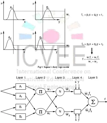
The basic structure of the type of fuzzy inference system could be seen as a model that maps input characteristics to input membership functions. Then it maps input membership function to rules and rules to a set of output characteristics. Finally it maps output characteristics to output membership functions, and the output membership function to a single valued output or a decision associated with the output. It has been considered only fixed membership functions that were chosen arbitrarily.
Figure 4 shows Sugeno‘s fuzzy logic model while Figure 5 shows the architecture of the ANFIS, comprising by input, fuzzification, inference and defuzzification layers. The network can be visualized
as consisting of inputs, with N neurons in the input layer and F input membership functions for each input, with F*N neurons in the fuzzification layer. There are FN rules with FN neurons in the inference and defuzzification layers and one neuron in the output layer. For simplicity, it is assumed that the fuzzy inference system under consideration has two inputs x and y and one output z as shown in Fig. 2. For a zero-order Sugeno fuzzy model, a common rule set with two fuzzy if-then rules is the following:
Rule 1: If x is A1 and y is B1, Then f1 = r1 (8) Rule 2: If x is A2 and y is B2, Then f2 = r2 (9)
Fig 4. Sugeno‘s fuzzy logic model
Fig 5. The architecture of the ANFIS with two inputs and one output
Here the output of the ith node in layer n is denoted as On,i:
Layer 1. Every node i in this layer is a square node with a node function:
1 i
O
= Ai(x), for i = 1, 2, (10) or,1 i
O
= Bi-2(y), for i = 3, 4 (11)
A1
A2
B1
B2 x
x
y
y
w1
w2
f1 = p1x + q1y + r1
f2 = p2x + q2y + r2
A1
A2
B1
B2
x
y
N
N
fx y
x y w1
w2
190
where x is the input to node-i, and Ai is the linguisticlabel (small , large, etc.) associated with this node function. In other words,
O
1i is the membershipfunction of Ai and it specifies the degree to which the given x satisfies the quantifier Ai. Usually Ai(x) is chosen to be bell-shaped with maximum equal to 1 and minimum equal to 0, such as the generalized bell function: i i i A
2b
a
c
x
1
1
(x)
(12)Parameters in this layer are referred to as premise parameters.
Layer 2. Every node in this layer is a circle node
labeled Π which multiplies the incoming signals and sends the product out. For instance,
2 i
O
= wi = Ai(x) x B(y), i = 1, 2. (13) Each node output represents the firing strength of a rule. (In fact, other T-norm operators that performs generalized AND can be used as the node function in this layer.)Layer 3. Every node in this layer is a circle node labeled N. The i-th node calculates the ratio of the
i-th rule‘s firing strengi-th to i-the sum of all rules firing
strengths: 2 1 i 3 i
w
w
w
w
O
, i = 1, 2. (14)For convenience, outputs of this layer will be called
normalized firing strengths.
Layer 4. Every node i in this layer is a square node with a node function:
)
i i i i i i 4i
w
f
w
(p
x
q
y
r
O
(15)where
w
i is the output of layer 3, and {pi, qi, ri} is the parameter set. Parameters in this layer will be referred to as consequent parameters.Layer 5. The single node in this layer is a circle node
labeled Σ that computes the overall output as the
summation of all incoming signals, i.e.,
i i 5i
w
f
O
(16)IV.METHODOLOGY
In this work, the control scheme of a synchronous generator in wind energy power system using adaptive neuro-fuzzy approach is presented. The control schemes and wind power system with permanent magnet synchronous generator have been developed in Matlab-Simulink software. The research steps are summarized in the flow chart as can be seen in Figure 4.
Fig 4. Research steps of this research
V.RESULTS AND DISCUSSION
In order to analyse the advantage of adaptive neuro-fuzzy method to control the permanent magnet synchronous generator in wind power system, the overall system is simulated using Matlab-Simulink software. The system described in this section
Literature review Start
Design the fuzzy logic controller
Design the fuzzy logic controller of the wind farm
Create the wind farm model using permanent magnet synchronous generator
Examine the fuzzy logic controller of the wind farm model
Examine the faults in the wind farm model
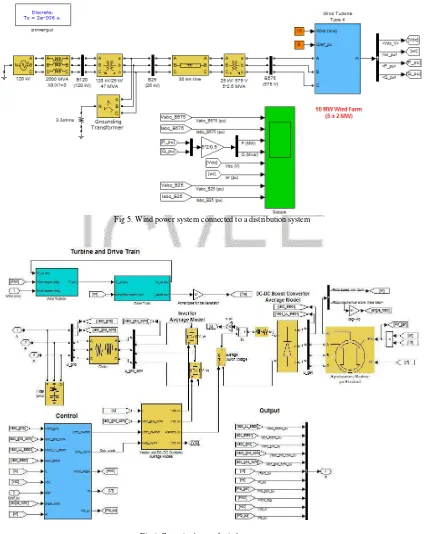
illustrates the steady-state and dynamic performance of a 10 MW wind farm connected to a distribution system. A 10 MW wind farm consisting of five 2 MW wind turbines connected to a 25 kV distribution system exports power to a 120 kV grid through a 30 km, 25 kV feeder. The system that created in Matlab-Simulink simulation software can be seen in Figure 5, while Figure 6 shows the control scheme of wind power system. In this research, type 4 wind turbine model is used. The Type 4 wind turbine presented in
this work consists of a synchronous generator connected to a diode rectifier, a DC-DC IGBT-based PWM boost converter and a DC/AC IGBT-based PWM converter modeled by voltage sources. The Type 4 technology allows extracting maximum energy from the wind for low wind speeds by optimizing the turbine speed, while minimizing mechanical stresses on the turbine during gusts of wind.
Fig 5. Wind power system connected to a distribution system
192
In this study, the wind speed is maintainedconstant at 15 m/s. The control system of the DC-DC converter is used to maintain the speed at 1 pu. The reactive power produced by the wind turbine is regulated at 0 MVAr.
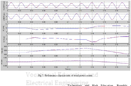
Figure 7 shows the performance characteristic of wind power system with PMSG using neuro-fuzzy controller. The variables shown in Figure 7 is the angular velocity, dc voltage, reactive power, active power, a phase current and voltage phase of a permanent magnet generator output.
Rotor angular velocity is relatively stable 1 pu up to t=0.03 seconds, but subsequently rose to 1.0005 pu which occurred up to time t = 0.15 seconds, and after that, there is experiencing stable again. Rotor angular velocity change is due to a short circuit on the
network that causes a voltage drop at the current time of 0.03 seconds. This voltage drop is as a consequence of the increase in network flows due to short circuit. Voltage changes that occur at t = 0.03 s also affect the amount of active power and reactive power generator. As shown in Figure 7 that there has been a reduction in active power of 10 MW to 7 MW at t = 0.03 s to t = 0.08 s. Conversely, the generator reactive power increases at t = 0.03 s is from 0 MVAr to 0.4 MVAr happens to t = 1 s, after which the system becomes unstable because it is controlled by the neuro fuzzy controller. In general it appears that the whole system parameters can be controlled well by controllers based on adaptive neuro-fuzzy approach.
Fig 7. Performance characteristic of wind power system
VI.CONCLUSION
In this study has demonstrated performance of intelligent controller based on adaptive neuro-fuzzy. This controller is used for controlling a permanent magnet synchronous generator (PMSG) that is used in wind power systems. The variables have been controlled are the angular velocity, dc voltage, reactive power, active power, a phase current and voltage phase of a permanent magnet generator output. The simulation results show that the adaptive neuro-fuzzy controller has successfully controlling all variables in a relatively short time to get back to a stable state.
ACKNOWLEDGMENT
The authors gratefully acknowledge the contributions of the Ministry of Research,
Technology and High Education, Republic of Indonesia, for funding this research.
REFERENCES
[1] R. Syahputra, I. Robandi, and M. Ashari, Optimization of Distribution Network Configuration with Integration of Distributed Energy Resources Using Extended Fuzzy Multi-objective Method, International Review of Electrical Engineering (IREE), vol.9, no.3, 2014.
[2] R. Syahputra, Distributed Generation: State of the Arts dalam Penyediaan Energi Listrik. LP3M UMY, Yogyakarta, 2012. [3] R. Syahputra, I. Robandi, and M. Ashari, ―Optimal
Distribution Network Reconfiguration with Penetration of
Distributed Energy Resources‖, in Proceeding of ICITACEE
2014, Semarang, Indonesia, 2014.
[4] R. Syahputra, I. Robandi, and M. Ashari, ―Performance Improvement of Radial Distribution Network with Distributed Generation Integration Using Extended Particle
[5] J.G. Slootweg, S. W. H. Haan, H. Polinder, and W.L. Kling.
―General Model for Representing Variable Speed Wind Turbines in Power System Dynamics Simulations‖. IEEE Trans. on Power Systems, Vol. 18, No. 1, February, 2003. [6] R. Syahputra, I. Robandi, and M. Ashari, Distribution
Network Efficiency Improvement Based on Fuzzy Multi-objective Method. IPTEK Journal of Proceedings Series. 2014; 1(1): 224-229.
[7] R. Syahputra, I. Robandi, M. Ashari, Modeling and Simulation of Wind Energy Conversion System in Distributed Generation Units, 3rd International Seminar on Applied Technology, Science and Arts (APTECS), 2011, pp. 290-296.
[8] S. Kim and E. Kim, ―PSCAD/EMTDC-based modeling and analysis of a gearless variable speed wind turbine‖, IEEE Trans Energy Conversion, Vol. 22, No. 2, pp. 421-430, 2007. [9] R. Syahputra, ―Fuzzy Multi-Objective Approach for the Improvement of Distribution Network Efficiency by Considering DG‖, IJCSIT, Vol. 4, No. 2, pp. 57-68, April 2012.
[10] R. Syahputra, I. Robandi, and M. Ashari, Reconfiguration of Distribution Network with DG Using Fuzzy Multi-objective Method, Int. Conference on Innovation, Management and Technology Research (ICIMTR), May 21-22, 2012, Melacca, Malaysia.
[11] R. Syahputra, I. Robandi, and M. Ashari, ―Performance Analysis of Wind Turbine as a Distributed Generation Unit in
Distribution System‖, International Journal of Computer Science & Information Technology (IJCSIT) Vol 6, No 3, pp. 39-56, June 2014.
[12] R. Syahputra, I. Robandi, and M. Ashari, ―PSO Based Multi -objective Optimization for Reconfiguration of Radial
Distribution Network‖, International Journal of Applied Engineering Research (IJAER), vol.10, no.6, 2015. pp. 14573-14586.
[13] R.N. Rohmah, A. Susanto, Indah Soesanti, M. Tjokronagoro, Computer Aided Diagnosis for lung tuberculosis identification based on thoracic X-ray, International Conference on Information Technology and Electrical Engineering (ICITEE), Yogyakarta, 2013.
[14] H. Afrisal, M. Faris, P. Utomo, Indah Soesanti, F. Andri, Portable smart sorting and grading machine for fruits using computer vision, International Conference on Computer, Control, Informatics and Its Applications, IC3INA 2013. [15] H.A. Nugroho, N. Faisal, I. Soesanti, L. Choridah. ―Analysis
of digital mammograms for detection of breast cancer‖.
Proceeding - 2014 International Conference on Computer, Control, Informatics and Its Applications: "New Challenges and Opportunities in Big Data", IC3INA 2014.
(u
J-)
(U
U
II
1.|-
T-at-J
l-(u
(J
+@- #
rtr
ICVET
International ConfErence on Vocati onal Educatisn andElectrical Engineering
I
CVE
E
2OT5
This
is
certify
that
Ra,vnadonbsyahputt
w
has
participated
on
I
St
INTEANATICNAL
CCiiFfEfNCE
CI\
VCCATTCNAL
EDUCATICI|
AiID
ELECTETCAL
ENCIN
ffQI
NG
s
Negeri
Surabaya
o
G
lt
o
l-J
q
l-o
El
o
7,g
lll
ut
IA.E
g
lOlg-o
=R!E
V-sJ1{
NePG'
H€Ef;
e
t
E
a
NrP.
196005191985031002
AS:
PRESENTER
Surabaya,
November
l8th
20ts
General
Chairman
of
ICVEE
2015
NIP.
195 11110797
9031001
Kfr
>h,
h
-sffi
?rl
ffffi-c
fgrros