Performance Evaluation of Wind Turbine with Doubly-Fed Induction
Generator
Agus Jamal
Department of Electrical Engineering, Faculty of Engineering UniversitasMuhammadiyah Yogyakarta, Yogyakarta, 55183, Indonesia
Slamet Suripto
Department of Electrical Engineering, Faculty of Engineering UniversitasMuhammadiyah Yogyakarta, Yogyakarta, 55183, Indonesia
Ramadoni Syahputra
Department of Electrical Engineering, Faculty of Engineering UniversitasMuhammadiyah Yogyakarta, Yogyakarta, 55183, Indonesia
Abstract
This paper presents the performance evaluation of wind turbine with doubly-fed induction generator. A stator flux oriented vector control is used for the variable speed doubly-fed induction generator operation. By controlling the generator excitation current the amplitude of the stator EMF is adjusted equal to the amplitude of the grid voltage. To set the generator frequency equal to the grid one, the turbine pitch angle controller accelerates the turbine and generator until it reaches the synchronous speed. The system is modeled and simulated in the Simulink software for modeling of all types of induction generator configurations. The model makes use of rotor reference frame using dynamic vector approach for machine model. The results of a single line to ground fault and a symmetrical three-phase ground fault is analyzed. The results show that the wind energy conversion system can normally operate in fault conditions.
Keywords: Distributed Generation, Doubly-Fed Induction Machine, Wind Energy Conversion Systems, Performance Evaluation.
INTRODUCTION
Distributed Generation (DG) is typically defined as small generators, usually less than 30-MW, that are connected to transmission or distribution systems [1]-[4]. The emerging new techniques such as small combustion turbines, fuel cells, wind energy, solar energy, and superconducting magnetic energy storage (SMES) make DGs more and more affordable and popular. The government of Indonesia has targeted that DGs from renewable energy resources for up to 23% of all new generation goingonline by the year 2025[5]-[8]. The target has been emerged because the conventional energy sources are limited and have pollution to the environment. In this case, wind energy is the most promising renewable energy source among them due to economically viable [9]-[11]. Many applications of wind power can be found in a wide power range from a few kilowatts to several megawatts in
small scale off-grid standalone systems or large scale grid-connected wind farms. Recently Enercon constructed a wind turbine of 4.5 MW with rotor diameter of 112.8 meters. Due to lack of control on active and reactive power, this type of distributed power generation causes problems in the electrical connected system [12]-[13]. So this requires accurate modeling, control and selection of appropriate wind energy conversion system.
Doubly-fed induction machines are receiving increasing attention for wind energy conversion system during such situation. Doubly-fed induction generator with vector control is very attractive to the high performance variable speed drive and generating applications [14]-[17]. With increasing penetration of wind-derived power in interconnected power systems, it has become necessary to model the complete wind energy systems in order to study their impact and also to study wind power plant control[18]-[20]. In this paper, an attempt to develop a dynamic model of induction machine which can be simulated as both motoring and generating mode when testing control strategies. Many researchers have been used the artificial intelligence in control strategies [21]-[28].Through the model developed in this paper can be used for simulating all types of induction generator configurations. The choice of synchronous rotating reference frame makes it particularly favorable for the simulation of doubly-fed configuration in transient conditions. The induction machine is modeled in vectorized form in the synchronous reference frame. A complete simulation model is developed for such machine under variable speed operation using Simulink environment.
DOUBLY-FED INDUCTION GENERATOR
mover, which makes it suitable for the application in fixed speed wind turbines. The fixed speed wind turbine uses a squirrel cage induction generator that is coupled to the power system through a connecting transformer. Figure 1 shows the wind turbine characteristics. Due to different operating speeds of the rotor and generator, a gearbox is used to match these speeds. The generator slip slightly varies with the amount of generated power and is therefore not entirely constant.
Figure 1: Wind turbine characteristics
General concept of the doubly-fed induction generator is shown in Figure 2.The mechanical power generated by the wind turbine is transformed into electrical power by an induction generator and is fed into the main grid through the stator and the rotor windings. The rotor winding is connected to the main grid by self-commutated AC/DC converters allowing controlling the slip ring voltage of the induction machine in magnitude and phase angle. In contrast to a conventional, singly-fed induction generator, the electrical power of a doubly-fed induction generator is independent from the speed. Therefore, it is possible to realize a variable speed wind generator allowing adjusting the mechanical speed to the wind speed and hence operating the turbine at the aerodynamically optimal point for a certain wind speed range.
Figure 2: Typical of doubly-fed induction generator
Half of the world’s leading wind turbine manufacturers use the doubly fed induction generator systems [14]. This isdue to the fact that the power electronic converter only has to handle a fraction (20% – 30%) of the total power, i.e., the slip power. This means that if the speed is in the range ±30% around the synchronous speed, the converte rhas a rating of 30% of the rated turbine power, reducingthe losses in the power electronic converter, compared toa system where the converter has to handle the totalpower. In addition, the cost of the converter becomes lower. The doubly fed induction machine has beenused in wind turbines for a long time. In the past, the ACACconverter connected to the rotor consisted of arectifier and inverter based on thyristor bridges.Nowadays, AC-AC converters are equipped with bidirectionalIGBT's, connecting the rotor of thevariable speed doubly fed induction generator to theelectrical grid.
SYSTEM MODELING
In this work, physical model of the wind energy conversion system with doubly-fed induction generator connected to grid of distribution system is created in Simulink software. The system models constituting elements of the system separately and also considers interrelationshipamong different elements within the system, where type and structure of the model is normally dictated by theparticular requirements of the analysis, e.g. steady-state, fault studies, etc. Indeed, due to the importance of more realisticproduction of the behavior of doubly-fed induction machine, it is intended to adopt physical model rather than functional model in order toaccurately assess performance of doubly-fed induction generator in the event of fault particularly in determining whether or not the generator willtrip following a fault. Figure 3 shows induction machine stator currents and grid-side converter currents, while Figure 4 shows the wind turbine model. In order to simulate the overall of the system, distribution power system with distributed generation including wind energy conversion system is also illustrated in Figure 5.
Figure 3: Induction machine stator currents and grid-side converter currents
Figure 5: Wind energy connected to a distribution system.
RESULTS AND DISCUSSION
The presented model is simulated using Simulink software to investigate the doubly-fed induction generator operation during starting, normal running, and fault conditions. The example described in this section illustrates the steady-state and dynamic performance of a 9 MW wind farm connected to a distribution system. The wind farm consists of six 1.5 MW wind turbines connected to a 25 kV distribution system exporting power to a 120 kV grid through a 30 km 25 kV feeder. A 2300V, 2 MVA plant consisting of a motor load (1.68 MW induction motor at 0.93 PF) and of a 200 kW resistive load is connected on the same feeder at bus B25. A 500 kW load is also connected on the 575 V bus of the wind farm. The diagram of this system in Matlab Simulink model is illustrated in Figure 5.
Both the wind turbine and the motor load have a protection system monitoring voltage, current and machine speed. The DC link voltage of the DFIG is also monitored. Wind turbines use a doubly-fed induction generator consisting of a wound rotor induction generator and an AC/DC/AC IGBT-based PWM converter. The stator winding is connected directly to the 60 Hz grid while the rotor is fed at variable frequency through the AC/DC/AC converter. The doubly-fed induction generator technology allows extracting maximum energy from the wind for low wind speeds by optimizing the turbine speed, while minimizing mechanical stresses on the turbine during gusts of wind. The optimum turbine speed producing maximum mechanical energy for a given wind speed is proportional to the wind speed. Another advantage of the doubly-fed induction generator technology is the ability for power electronic converters to generate or Turbine Data Menu and the Turbine Power Characteristics absorb reactive power, thus eliminating the need for installing capacitor banks as in the case of squirrel-cage induction generators.The terminal voltage will be controlled to a value imposed by the reference voltage (Vref=1 pu) and the voltage droop (Xs=0.02 pu).
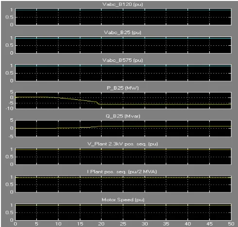
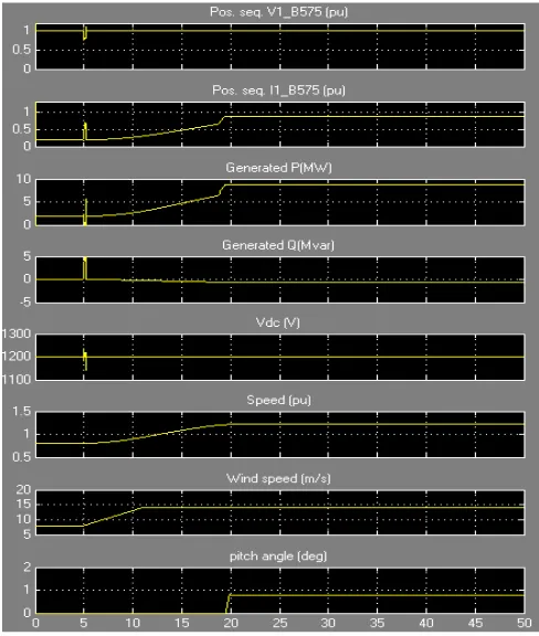
Simulation of Turbine Response to a Change in Wind Speed In this section, the turbine response to a change in wind speed is observed. Initially, wind speed is set at 8 m/s, and then at t=5s, wind speed increases suddenly at 14 m/s. Figure 6shows the waveforms associated with this simulation. At t = 5s, the generated active power starts increasing smoothly (together with the turbine speed) to reach its rated value of 9MW in approximately 15s. Over that time frame the turbine speed increases from 0.8 pu to 1.21 pu.
Figure 6: Waveforms for a gust of wind in voltage regulation mode.
Initially, the pitch angle of the turbine blades is zero degree and the turbine operating point follows the red curve of the turbine power characteristics up to point D. Then the pitch angle is increased from 0 deg to 0.76 deg to limit the mechanical power.
The voltage and the generated reactive power is also observed. The reactive power is controlled to maintain a 1 pu voltage. At nominal power, the wind turbine absorbs 0.68 MVar (generated Q=-0.68 MVar) to control voltage at 1pu. If the mode of operation is changed to Varregulation with the Generated reactive power Qrefset to zero, the voltage increases to 1.021 pu when the wind turbine generates its nominal power at unity power factor.
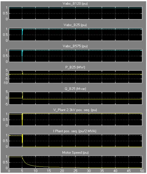
Simulation of Single Line to Ground Fault on the 25 kV System
In this section, the impact of a voltage sag resulting from a remote fault on the 25 kV system is observed. In this simulation the mode of operation is initially Var regulation with Qref=0 and the wind speed is constant at 8 m/s. A 0.15 pu voltage drop lasting 0.5 s is programmed, in the 25 kV voltage source menu, to occur at t=5 s. The simulation results are illustrated in Figure 8. for voltage regulation mode and Figure 9. for Varregulation mode. The plant voltage and current as well as the motor speed can be observed. Note that the wind farm produces 1.87 MW. At t=5 s, the voltage falls below 0.9 pu and at t=5.22 s, the protection system trips the plant because an under-voltage lasting more than 0.2 s has been detected (exceeding protection settings for the Plant subsystem). The plant current falls to zero and motor speed decreases gradually, while the wind farm continues generating at a power level of 1.87 MW. After the plant has tripped, 1.25 MW of power (P_B25 measured at bus B25) is exported to the grid.
Figure 8: Waveforms for a single line to ground fault on 25 kV system in voltage regulation mode.
Figure 9: Waveforms for a single line to ground fault on 25 kV system in Varregulation mode.
As can be seen in Figure 9 that the plant does not trip anymore. This is because the voltage support provided by the 5 Mvar reactive power generated by the wind turbines during the voltage sag keeps the plant voltage above the 0.9 pu protection threshold. The plant voltage during the voltage sag is now 0.93 pu.
Simulation ofSymmetrical Three Phase Fault on the 25 kV System
Figure 10: Waveforms for a symmetrical three phase fault on 25 kV system in voltage regulation mode.
Figure 11: Waveforms for a symmetrical three phase fault on 25 kV system in Varregulation mode.
CONCLUSIONS
This paper presents the performance evaluation of wind turbine with doubly-fed induction generator. A stator flux oriented vector control is used for the variable speed doubly-fed induction generator operation. By controlling the generator excitation current the amplitude of the stator EMF is adjusted equal to the amplitude of the grid voltage. To set the generator frequency equal to the grid one, the turbine pitch angle controller accelerates the turbine and generator until it reaches the synchronous speed. The system is modeled and simulated in the Simulink software for modeling of all types of induction generator configurations. The model makes use of rotor reference frame using dynamic vector approach for machine model. The results of a single line to ground fault and a symmetrical three-phase ground fault is analyzed. The results show that the wind energy conversion system can normally operate in fault conditions.
REFERENCES
[1] A. Jamal, R. Syahputra, (2011), “Model Power System Stabilizer Berbasis Neuro-Fuzzy Adaptif”,
SemestaTeknika, Vol. 14, No. 2, 139-149, 2011, pp.
139-149.
[2] A. Jamal, S. Suripto, R. Syahputra, (2015),“ Multi-Band Power System Stabilizer Model for Power Flow Optimization in Order to Improve Power System Stability”, Journal of Theoretical and Applied
Information Technology (JATIT),Vol. 80, No. 1, 2015;
pp. 116-123.
[3] R. Syahputra, I. Robandi, M. Ashari, (2014),
“Distribution Network Efficiency Improvement Based on Fuzzy Multi-objective Method”. IPTEK Journal of
Proceedings Series. 2014; 1(1): pp. 224-229.
[4] R. Syahputra, (2012), “Distributed Generation: State of the Arts dalamPenyediaanEnergiListrik”,LP3M UMY, Yogyakarta, 2012.
[5] R. Syahputra, I. Robandi, M. Ashari, (2012),
“Reconfiguration of Distribution Network with DG Using Fuzzy Multi-objective Method”, International
Conference on Innovation, Management and
Technology Research (ICIMTR), May 21-22, 2012,
Melacca, Malaysia.
[6] R. Syahputra, I. Robandi, M. Ashari, (2014),
“Optimization of Distribution Network Configuration with Integration of Distributed Energy Resources Using Extended Fuzzy Multi-objective Method”,
International Review of Electrical Engineering
(IREE), vol.9, no.3, 2014, pp. 629-639.
[7] R. Syahputra, I. Robandi, M. Ashari, (2014), “Optimal Distribution Network Reconfiguration with Penetration of Distributed Energy Resources”,
Proceeding of 2014 1st International Conference on Information Technology, Computer, and Electrical Engineering: Green Technology and Its Applications
for a Better Future, ICITACEE 2014, Semarang,
Indonesia.
[8] R. Syahputra, I. Robandi, M. Ashari, (2015), “PSO Based Multi-objective Optimization for Reconfiguration of Radial Distribution Network”,
Research (IJAER), vol.10, no.6, 2015. pp. 14573-14586.
[9] R. Syahputra, (2013), “A Neuro-Fuzzy Approach For the Fault Location Estimation of Unsynchronized Two-Terminal Transmission Lines”, International
Journal of Computer Science & Information
Technology (IJCSIT), Vol. 5, No. 1, pp. 23-37.
[10] R. Syahputra, I. Robandi, M. Ashari, (2015),
“Performance Improvement of Radial Distribution
Network with Distributed Generation Integration Using Extended Particle Swarm Optimization
Algorithm”, International Review of Electrical
Engineering (IREE), vol.10, no.2, 2015. pp.293-304.
[11] R. Syahputra, I. Robandi, M. Ashari, (2015),
“Reconfiguration of Distribution Network with DER Integration Using PSO Algorithm”, TELKOMNIKA, vol.13, no.3, 2015. pp.759-766.
[12] R. Syahputra, (2012), “Fuzzy Multi-Objective Approach for the Improvement of Distribution Network Efficiency by Considering DG”,
International Journal of Computer Science &
Information Technology (IJCSIT), Vol. 4, No. 2, pp.
57-68.
[13] R. Syahputra, M. Ashari,I. Robandi, (2011),
“Modeling and Simulation of Wind Energy Conversion System in Distributed Generation Units”.
International Seminar on Applied Technology, Science
and Arts (APTECS). 2011; pp. 290-296.
[14] R. Syahputra, I. Robandi, M. Ashari, (2011), “Control of Doubly-Fed Induction Generator in Distributed Generation UnitsUsing Adaptive Neuro-Fuzzy Approach”. International Seminar on Applied
Technology, Science and Arts (APTECS). 2011; pp.
493-501.
[15] R. Syahputra, I. Robandi, M. Ashari, (2014),
“Performance Analysis of Wind Turbine as a Distributed Generation Unit in Distribution System”,
International Journal of Computer Science &
Information Technology (IJCSIT), Vol. 6, No. 3, pp.
39-56.
[16] Afrisal, H., Faris, M., Utomo P., G.,Grezelda, L., Soesanti, I., Andri F., M. (2013). Portable smart sorting and grading machine for fruits using computer vision. Proceeding-2013 International Conference on
Computer, Control, Informatics and Its Applications,
IC3INA 2013, pp. 71-75.
[17] Soesanti, I. (2016).Web-Based Monitoring System on the Production Process of Yogyakarta Batik Industry,
Journal of Theoretical and Applied Information
Technology, 87(1), pp. 146-152.
[18] Syahputra, R., Soesanti, I. (2016). Design of Automatic Electric Batik Stove for Batik Industry.
Journal of Theoretical and Applied Information
Technology, 87(1), pp. 167-175.
[19] Syahputra, R., Soesanti, I., Ashari, M. (2016). Performance Enhancement of Distribution Network with DG Integration Using Modified PSO Algorithm.
Journal of Electrical Systems, 12(1), pp. 1-19.
[20] Rohmah, R.N., Susanto, A., Soesanti, I. (2013). Lung tuberculosis identification based on statistical feature of thoracic X-ray. 2013 International Conference on
Quality in Research, QiR 2013 - In Conjunction with ICCS 2013: The 2nd International Conference on
Civic Space, pp. 19-26.
[21] Soesanti, I.,Syahputra, R. (2016). Batik Production Process Optimization Using Particle Swarm OptimizationMethod.Journal of Theoretical and
Applied Information Technology, 86(2), pp. 272-278.
[22] Rahadian, H., Sutopo, B., Soesanti, I. (2015). TGS2611 performance as biogas monitoring instrument in digester model application. Proceeding -
2015 International Seminar on Intelligent Technology
and Its Applications, ISITIA 2015, pp.119-124.
[23] Nugroho, H.A.,Faisal, N.,Soesanti, I.,Choridah, L. (2014). Analysis of digital mammograms for detection of breast cancer. Proceeding - 2014 International
Conference on Computer, Control, Informatics and Its Applications: "New Challenges and Opportunities in
Big Data", IC3INA 2014, pp. 25-29.
[24] Rohmah, R.N., Susanto, A., Soesanti, I., Tjokronagoro, M. (2013). Computer Aided Diagnosis for lung tuberculosis identification based on thoracic X-ray.
Proceedings - 2013 International Conference on Information Technology and Electrical Engineering: "Intelligent and Green Technologies for Sustainable
Development", ICITEE 2013, pp.73-78.
[25] Ratnasari, N.R., Susanto, A., Soesanti, I., Maesadji. (2013). Thoracic X-ray features extraction using thresholding-based ROI template and PCA-based features selection for lung TB classification purposes.
Proc. of 2013 3rd Int. Conf. on Instrumentation,
Communications, Information Technol., and
Biomedical Engineering: Science and Technol. for Improvement of Health, Safety, and Environ.,
ICICI-BME 2013, pp.65-69.
[26] Nugroho, H.A., Faisal, N., Soesanti, I.,Choridah, L. (2014). Identification of malignant masses on digital mammogram images based on texture feature and correlation based feature selection. Proceedings - 2014
6th International Conference on Information Technology and Electrical Engineering: Leveraging Research and Technology Through
University-Industry Collaboration, ICITEE 2014, pp. 1-6.
[27] Jamal, A., Syahputra, R. (2013). UPFC Based on Adaptive Neuro-Fuzzy for Power Flow Control of Multimachine Power Systems. International Journal
of Engineering Science Invention, 2(10), 05-14.
[28] Syahputra, R. (2016). Application of Neuro-Fuzzy Method forPrediction of Vehicle Fuel Consumption.
Journal of Theoretical and Applied Information