DESIGN OF CONTROL UNIT/ DATA PATH FOR PRODUCTION MONITORING SYSTEM USING FPGA BASED ON OVERALL EQUIPMENT
EFFECTIVENESS (OEE)
CHANG SHI MEI
This Report Is Submitted In Partial Fulfillment Of The Requirements For The Bachelor Degree Of Electronic Engineering (Industrial Electronic)
Fakulti Kejuruteraan Elektronik dan Kejuruteraan Komputer UNIVERSITI TEKNIKAL MALAYSIA MELAKA
ii i “I hereby, declare this report is the result of my own research except as cited in the
references.”
Signature : …….………
Author Name : CHANG SHI MEI
iv
“I hereby declare that I have read through this report and found that it has comply the partial fulfilment for awarding the degree of Bachelor of Electronic Engineering
(Industrial Electronic).”
Signature : …….……….
Name : EN. IMRAM BIN HINDUSTAN
v
vi
ACKNOWLEDGMENT
In preparing this thesis, I had contacted with many peoples and academicians in helping me completing this project. They have contributed toward my understanding, and also guidance. First of all, I wish to express my sincere appreciation to my thesis supervisor En Imran Bin Hindustan for the kindness, encouragement, valuable guidance, advices, suggestion and providing useful information throughout this project.
My sincere gratitude is also extended to all lecturers in Universiti Teknikal Malaysia Melaka who have being teaching me for their contribution and knowledge. Moreover I would like to thanks all my friends and other individuals who provide assistance on various occasions. Their view, suggestions and tips are useful in helping me to complete this thesis.
vii
ABSTRACT
A Production Monitoring System (PMS) is a set of equipment placed on a production line to monitor the status of a process or manufacturing line. It collects, process, stores and displays production information. Nowadays, with the rapid grow of technologies, the conventional PMS is not suggested to be used in industries. This method is not efficient because it‟s time consuming and the collected data are not reliable and inaccuracies due to human errors and intervention. Hence, an automated PMS project is proposed. The automated PMS is fully automated in data collection, processing and recording. Basically, the aims of this project is to design a Control Unit /data path by translating the Overall Equipment Effectiveness (OEE) concept into a set of logic units that described using Very High speed integrated circuit Hardware Description Language (VHDL) and to be implemented in a programmable digital logic
chip called Field Programmable Gate Array (FPGA). Normally, the performance and
viii
ABSTRAK
Sistem Pemantauan Pengeluaran (PMS) adalah satu set peralatan yang diletakkan pada barisan pengeluaran untuk memantau status sesuatu proses atau pembuatan talian. Ia mengumpul, memproses, menyimpan dan memaparkan maklumat pengeluaran. Pada masa kini, dengan kepesatan teknologi, PMS konvensional tidak dicadangkan untuk digunakan dalam industri. Kaedah ini tidak berkesan sebab ia memakan masa dan data yang dikumpul tidak boleh dipercayai dan tidak tepat kerana kesilapan manusia. Oleh itu, projek PMS automatik dicadangkan. PMS automatik adalah automatik sepenuhnya dalam pengumpulan data, pemprosesan dan rakaman. Pada asasnya, matlamat projek ini adalah untuk mereka bentuk laluan Unit Kawalan / Data Jalan dengan menterjemahkan Keberkesanan Peralatan Keseluruhan konsep (OEE) ke dalam satu set unit logik yang diterangkan menggunakan kelajuan tinggi Sangat litar bersepadu Perkakasan Penerangan Bahasa (VHDL) dan akan dilaksanakan dalam cip logik digital
diprogramkan dipanggil Field Programmable Gate Array (FPGA). Biasanya, prestasi
ix
TABLE OF CONTENTS
CHAPTER TITLE PAGE
PROJECT TITLE i
PROJECT STATUS FORM ii
STUDENT’S DECLARATION iii
SUPERVISOR’s DECLARATION iv
DEDICATION v
ACKNOWLEDGEMENT vi
ABSTRACT vii
ABSTRAK viii
TABLE OF CONTENTS ix
LIST OF TABLES xiii
LIST OF FIGURES xv
LIST OF ABBREVIATIONS xvii
I INTRODUCTION 1
1.1 Production Monitoring System (PMS) 1
1.2 Problem Statement 2
1.3 Objectives 3
1.4 Scope of Project 3
x
II LITERATURE REVIEW 6
2.1 Production Line 6
2.2 Types of Production Lines 7
2.3 Factors towards Inefficiency in Production
Lines
10
2.3.1 Machine Efficiency 10
2.3.2 Man power Utilization 11
2.3.2.1 Supporting Department 11
2.3.2.2 Operators and Workers 12
2.4 Existing Production Monitoring System
(PMS)
12
2.4.1 The concept of JIDOKA 12
2.4.2 White board or Tracking sheets 13
2.4.3 Real time Production Monitoring
System (PMS)
14
2.4.4 Embedded controller for PMS
based on OEE using FPGA
15
2.4.5 Comparison between related
project journal
16
2.5 Overall Equipment Effectiveness (OEE) 20
2.5.1 OEE Losses 20
2.5.2 OEE Factors 22
2.6 Hardware Description Language (HDL) 26
III METHODOLOGY 27
3.1 Methodology 27
xi
3.3 Project Planning 29
3.4 Block diagram of Production Monitoring
System
31
3.5 Block Diagram of Processor 32
3.6 Design Process 33
3.6.1 Development of instruction
sequences
34
3.6.2 Design of Logic Circuit 37
3.6.2.1 Control Unit 37
3.6.2.2 Data Path 44
3.6.3 Describe Logic Units in VHDL 45
IV RESULTS AND DISCUSSIONS 47
4.1 VHDL Modules 47
4.2 VHDL Test Bench 48
4.2.1 Four – Bit Adder 48
4.2.1.1 Adder with 2 Inputs 48
4.2.1.2 Adder with 3 Inputs 49
4.2.2 Register 51
4.2.3 Control Unit 53
4.2.4 Processor 57
V CONCLUSION 67
5.1 Project Conclusion 67
xii
REFERENCES 70
APPENDIX 72
APPENDIX A 72
APPENDIX B 95
xiii
LIST OF TABLES
NO TITLE PAGE
2.1 Comparison between the related project journal 17
2.2 The three general OEE loss 21
2.3 OEE factors and efficiency loss 22
2.4 World class percentage for each OEE factors 24
2.5 Production line data of the industry 25
2.6 Calculation of support variable based on Table 2.5
information 25
2.7 Calculation of OEE factor percentage 26
3.1 The six external data enters the data path 32
3.2 Assignment of alphabet to every involved OEE
parameter 34
3.3 Efficiency loss and OEE factors 35
3.4 The instruction sequences without present of clock
signal 35
3.5 The instruction sequences with present of clock
signal 36
3.6 The next state/ implementation table according to
instruction sequences 39
4.1 The three conditions of register 51
xiv
4.3 The next state/ implementation table according to
instruction sequence 54
4.4 Three set of examples going to test the processor
xv
LIST OF FIGURES
NO TITLE PAGE
1.1 Block diagram of control unit/data path for
production monitoring system. 4
2.1 Types of production lines 8
2.2 Manual manufacturing process 8
2.3 Semi-automated manufacturing process 9
2.4 Automated manufacturing line 9
2.5 Three major factor affecting production lines in
industries 10
2.6 The interaction of andon system 13
2.7 The white board uses to record the production
status 14
2.8 Block diagram of the real time PMS 14
2.9 Embedded controller for Production Monitoring
System 16
3.1 Flow chart of project development 28
3.2 The project Gantt chart 30
3.3 Block Diagram of Production Monitoring System 31
3.4 Block diagram of initial design of processor to be
embedded on an FPGA 33
xvi
3.6 The K-maps and excitation for control signals and
D flip-flops 40
3.7 The logic circuit of control unit 43
3.8 The logic circuit of data path 46
4.1 The simulation waveform of 2 inputs adder 49
4.2 The simulation waveform of 3 inputs adder 50
4.3 The logic symbol of register used in project 51
4.4 The simulation waveform of register 52
4.5 The simulation waveform of control unit 55
4.6 The RTL schematic of control unit 56
4.7 The simplified simulation behavioral model of
processor with output 1101 58
4.8 The simulation behavioural model of processor in
details with output 1101 59
4.9 The simplified simulation behavioral model of
processor with output 1000 61
4.10 The simulation behavioural model of processor in
details with output 1000 62
4.11 The simplified simulation behavioral model of
processor with output 0111 63
4.12 The simulation behavioural model of processor in
details with output 0111 64
4.13 The RTL schematic of processor 66
5.1 The block diagram of automated Production
xvii
LIST OF ABBREVIATION
ALU Arithmetic Logic Unit
FSM Finite State Machine
FPGA Field Programmable Gate Array
GUI Graphical User Interface
IC Integrated Circuit
IR Infrared
LCD Liquid Crystal Display
LED Light Emitting Diode
OEE Overall Equipment Effectiveness
PC Personal Computer
PCB Printed Circuit Board
PMS Production Monitoring System
PPC Production Planning and Control
TQM Total Quality Management
VHDL Very High speed integrated circuit Hardware Description
1 CHAPTER 1 INTRODUCTION
This chapter will discuss about the overview of process that involved in design the control unit and data path. It discuss about the introduction, problem statement, objectives and scope of the project. The end of this chapter will list the thesis outline.
1.1 Production Monitoring System (PMS)
2 roduction line targets concurrently acts as a calling unit to inform respective personnel at the right time on production line problems.
From research, a number of production floors are utilizing manual methods of data collection for producing reports. Manual data compilation leaves room for both inconsistencies and inaccuracies. When manual data collection is practiced, it always involves manual data compiling. This is mostly accomplished by entering in the information into spreadsheets for recording. Whenever the human intervention occurs on the recording or collection of data, the truthfulness of the collected data is no longer reliable. Factors affect the collected data may not be truthful are due to the improper monitoring system, the inaccuracy of the monitoring device and human intervention.
Therefore, this study is conducted to explain the usefulness of an automated data collection tool and display system for production lines. Develop an automated real time PMS to replace human supervision on production lines is extremely needed due to information obtained from production lines is essential for the management to enhance the production yield in all stages. Capturing and interpreting this production data without human intervention is a major challenge for the management.
1.2 Problem Statement
3 Nowadays, there are various types of monitoring systems practiced in the industries. Monitoring system involve manual approach such as charting on a white board or tracking sheets. A person in-charged is responsible on keeping tracks of the line status and records the operation performance, such as the amount of good or reject products on a white board. This method is not efficient because it is time consuming and there is a possibility that the collected data are not reliable and less accurate due to human errors and intervention.
In year 2009, a real time PMS was developed by Siva Kumar. This system is used in real time to record production line problems. It is built by using programmable logic controller and sensor to collect data from production lines. However the processing and recording parts were still done manually. It is not practical to process and record a big set of information manually due to possibilities of human errors and workers lack of good work ethic. A line supervisor or operator might forget to record or simply miscount the number of goods, caused the management team, maintenance and engineering personnel misinterpret the status of production line. In addition, in some circumstances, faults and mistakes which occur on the process line can be overwritten and fabricated. Thus, an automated production monitoring system is needed in data collection, processing and recording to improve the data accuracy and reliability.
1.3 Objectives
4 1.4 Scope of Project
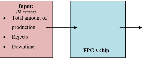
[image:21.612.126.425.291.413.2]This study is conducted to further enhance the existing production monitoring system (PMS). The system should be able to perform automated data collection, processing and recording. The automated data inputs are three important information that need to be monitored by a production monitoring system (PMS) from the production line. They are total amount of production over a certain period of time, total amount of rejects and total downtime or breakdown time. Through the data processing done by an FPGA chip, the system displays the output on a text Liquid Crystal Display (LCD) display module. Figure 1.1 illustrates the suggested system to be designed.
Figure 1.1: Block diagram of control unit/data path for production monitoring system.
1. This project is part of a bigger system. The project is only concern about the design
of control unit/ data path for production monitoring system (PMS) but not involve the ALU part.
2. The FPGA chip is programmed to work as a processing unit, it capable to control
more data inputs from production lines.
3. The Overall Equipment Effectiveness (OEE) concept is used in this project to
measure the performance and efficiency of production line.
4. The OEE concept is translated into a set of logic units which are described using
Very high speed integrated circuit Hardware Description Language (VHDL).
5. For the processor, the received data inputs perform data processing to determine
Overall Equipment Effectiveness (OEE) indicator and its parameters (Availability, Performance, Quality and OEE).
Input: (IR sensor)
Total amount of
production
Rejects
Downtime
Output:
5
6. This project used Xinlinx ISE Design Suite 11 for design entry, design analysis and
synthesis. ISim simulator is used for design simulation.
7. Finally, comparison between the simulation results and mathematical calculations is
required to verify the VHDL program is validate.
1.5 Outline of Thesis
In this thesis, there are involve of five chapter to describe the project of Design of control unit/ data path for Production Monitoring System by using FPGA based on overall equipment effectiveness which is starting with Introduction, Literature Review, Methodology, Result and Discussion and Conclusion and Recommendation.
Chapter 1: Introduction of the project that discussed the background of the study, problem statement, scopes and objectives of developing this project.
Chapter 2: Literature Review consist the background study and research before developing this project. The content of the background studies such as the information about the Production Monitoring System, VHDL, OEE concept and etc.
Chapter 3: Methodology described about the methods or approaches used in solving the project. In this chapter, it contains a block diagram and flow chart to explain the procedures of designing the project. The circuit design is discussed as well.
Chapter 4: Concentrates on the result and discussion of this project. This chapter consists of the simulation, results and analysis of the product performance.
6 CHAPTER 2 LITERITURE REVIEW
This chapter contains the literature review on theoretical concepts applied in this project. It contains the information that the project required in order to develop and complete the entire project.
2.1 Production Line
Refer to Cambridge dictionaries, production line is a set of machines and worker in a manufacturing plant that a product flows along while it is being made or produced. Every machine or worker must be complete performs specific job before the product proceeds to the next station in production line.
7 Accuracy and efficiency on the production lines allow an improved production and application of usable resources within industries (Siva, et. al., 2009). The better line efficiency will be able to assist companies or industries to generate higher yield and revenue. Hence, a Production Monitoring System (PMS) is essential to install at manufacturing line to help collect and distribute line information to everyone in the shop floor as production are happening. The task of the production tool is to aid the manufacturing team to perform their best within the usable resources. Moreover, improve quality matters and reducing overheads.
Generally, the Overall Equipment Effectiveness (OEE) as an ultimate efficiency tool for machineries and equipment in manufactory. It is concept of determining the performance indicators of a production line, which involves arithmetic and logic operations for data processing.