THE ANALYSIS OF FLUID STRUCTURE INTERACTION FOR SUBMERSIBLE WATER-HYDRAULIC MANIPULATOR USING
COMPUTATIONAL FLUID DYNAMICS
MUHAMMAD ZUL FIKRI BIN SUHAIMI
i
SUPERVISOR DECLARATION
“I hereby declare that I have read this thesis and in my opinion this thesis is sufficient in terms of scope and quality for the award of the degree of Bachelor of
Mechanical Engineering (Thermal-Fluids)”
ii
THE ANALYSIS OF FLUID STRUCTURE INTERACTION FOR SUBMERSIBLE WATER-HYDRAULIC MANIPULATOR USING
COMPUTATIONAL FLUID DYNAMICS
MUHAMMAD ZUL FIKRI BIN SUHAIMI
This thesis is submitted in partial fulfilment of the requirement for the degree of Bachelor Mechanical Engineering with Honours (Thermal-Fluid)
Faculty of Mechanical Engineering Universiti Teknikal Malaysia Melaka
iii
DECLARATION
“I hereby declared that the work in this thesis is my own except for summaries quotation which have been duly acknowledged”
Signature : ………..
iv
This report is dedicated to my family. Thank you for your continuous support during my vital educational years. Without their patience, understanding and most of all
love, the completion of this work would not have been possible.
To my beloved parents,
Sharifah Binti Mohd Suhaimin@Abdul Rahman &
Suhaimi Bin Yusoff
My siblings,
Muhammad Amiruddin Bin Suhaimi Mohammad Faizal Bin Suhaimi
Siti Nur Hafizah Binti Suhaimi Muhammad Hazim Bin Suhaimi
v
ACKNOWLEDGEMENT
“In The Name Of Allah, The Merciful, The Beneficent”
Glory to Allah S.W.T. the most gracious and most merciful. All the worship belongs to only Allah. We seek refuge with Allah from the wickedness within evil and until I have done the project. I also praised to Allah S.W.T for giving us courage, time, and knowledge in doing this report for Bachelor Degree Project.
Alhamdulillah, the report can be submitted on the due date. The successful of this project is because of the encouragement and support of many people. I wish to express my gratitude to my supervisor, Dr. Ahmad Anas Bin Yusof who was abundantly helpful and offered invaluable assistance, support and guidance and also deepest appreciation to co-supervisor, Engr. Mohd Noor Asril Bin Saadun. Without continued support and interest on the project.
vi
ABSTRACT
vii
ABSTRAK
viii
TABLE OF CONTENT viii
LIST OF FIGURES xi
LIST OF TABLES
LIST OF ABBREVIATION
xiii xiv
CHAPTER 1 INTRODUCTION 1
CHAPTER 2
1.1 BACKGROUND
1.2 PROBLEM STATEMENT 1.3 PROJECT OBJECTIVE 1.4 PROJECT SCOPE
LITERATURE REVIEW 2.1 INTRODUCTION
ix
CHAPTER 3
CHAPTER 4
2.2.4 CFD Post Processing
2.3 ANALYSIS CONSIDERING JOINT 2.4 ANALYSIS FLUID FLOW CONDITION 2.5 EARLY CFD SIMULATION
2.5.1 Defects During Simulation
METHODOLOGY 3.1 FLOW CHART
3.2 DIMENSIONING MODEL
x
xi
LIST OF FIGURES
FIGURE TITLE PAGE
2.1 Slave arm including a flexible joint driven by water pressure 8 2.2 Review of the pre-processing and meshing results for the CFD
analysis
9
2.3 Velocity (a) and pressure (b) distribution at 0.5, 3.5 and 5knots 10
2.4 Drawing of half prototype 11
2.5 Early sizing setup feature 12
3.1 Project flow chart 15
3.2 Model prototype for analysis 17
3.3 Overall program in ANSYS Workbench 17
3.4 Drag and drop the Fluid Flow(FLUENT) module 18
3.5 Detail of mesh 19
3.6 3.7 3.8 3.9
Problem Setup for the model Prototype first position
Fluid flow direction facing streamlines and blunt body Individual simulation in medium for model position
xii
Static pressure contour for first position.
Pressure contour for first condition in water vapor Velocity vector for first condition in water vapor Pressure contour for first condition in air
Velocity vector for first condition in air
Pressure contour for first condition in water liquid Velocity vector for first condition in water liquid
Pressure contour for first condition blunt body in water vapor Velocity vector for first condition blunt body in water vapor Pressure contour for first condition blunt body in air
Velocity vector for first condition blunt body in air
Pressure contour for first condition blunt body in water liquid Velocity vector for first condition blunt body in water liquid Pressure contour for extend condition in water vapor
Velocity vector for extend condition in water vapor Pressure contour for extend condition in air
Velocity vector for extend condition in air
Pressure contour for extend condition in water liquid Velocity vector for extend condition in water liquid
Pressure contour for extend condition blunt body in water vapor Velocity vector for extend condition blunt body in water vapor Pressure contour for first condition blunt body in air
Velocity contour for first condition blunt body in air
Pressure contour for first condition blunt body in water liquid Velocity contour for first condition blunt body in water liquid
xiii
LIST OF TABLES
TABLE TITLE PAGE
2.1
3.1 4.1 5.1 5.2
Convergence study result with UDR CFD model at the speed 3.5 knots.
Angle and position Prototype first position.
Curvature normal angle and nodes generated Minimum size and nodes generated
10
xiv
LIST OF ABBREVIATION
ANSYS = Analysis System
CAD = Computer Aided Drawing CAE = Computer-Aided Engineering CFD = Computational Fluid Dynamics DOF = Degree Of Freedom
ROV = Remotely Operated Vehicle
1
CHAPTER 1
INTRODUCTION
1.1 BACKGROUND
According Vehicle teleoperation first appeared in the early 1900’s, but it was not until the 1970’s that systems became widely used [1]. Back then, the underwater ROV is mainly used in oil industry while manned submersible vehicle is the preferred tools for underwater scientific studies. As the technology developed, its functions have expended to be used in both industries and scientific studies. ROV is defined as the underwater robot that allows the vehicle’s operator to remain in contented environment while the piloted robot performs the work underwater.
The manipulator arm design has to be optimized to increase its working efficiency. Computer-Aided Engineering (CAE) is the most suitable technology to perform optimization. CAE is the use of information technology to support engineers in tasks such as analysis, simulation, design, manufacture, planning, diagnosis, and repair. Software tools that have been developed to support these activities are considered as CAE tools. CAE tools are being used to analyze the robustness and performance of components and assemblies. The term encompasses simulation, validation, and optimization of products and manufacturing tools.
2
simulation. This analysis technique is widely used that range of industrial and non-industrial application areas.
This project studies about design and analysis of the submersible hydraulic manipulator which shows the capability of the manipulator arm design and its features according to the analysis that will be performed. This computer based simulation is important because it can simulate the fluid that pass through the manipulator arm at different angle. Furthermore, simulation and analysis of the fluid flow in term of velocity and pressure distribution can be implemented into this project to detect any excessive pressure build that may happen to the manipulator arm that analytically based from underwater characteristic.
1.2 PROBLEM STATEMENT
3
1.3 PROJECT OBJECTIVE
The objective of this project are as follow:
i. To evaluate water powered underwater manipulator pressure distribution using CFD.
1.4 PROJECT SCOPE
The scope of the project is used to show the limitation of the research of the project. The scopes of the project are as follows:
i. Using robotic arm as the submersible water-hydraulic manipulator for evaluating underwater manipulator performance in air medium.
ii. Using robotic arm as the submersible water-hydraulic manipulator for evaluating underwater manipulator performance in water vapor medium.
4
CHAPTER 2
LITERATURE REVIEW
2.1 INTRODUCTION
This chapter will discuss about the research literature. Some concept of a project is described. This because an understanding of the work will assist in preparing the project end of this year. The background study or literature review come from various resources such as:
1. Books 2. Journals
5
2.2 COMPUTATIONAL FLUID DYNAMICS
2.2.1 ANSYS Fluent
ANSYS Fluent software contains the broad physical modeling capabilities needed to model flow, turbulence, heat transfer, and reactions for industrial applications ranging from air flow over an aircraft wing to combustion in a furnace, from bubble columns to oil platforms, from blood flow to semiconductor manufacturing, and from clean room design to wastewater treatment plants [3]. For the project, this software is been used generally to do analysis for the prototype model that been proposed.
2.2.2 CFD Pre-processing
i. Geometry
In obtaining the fluid region from the data computed in the CFD, the geometry must be applied to the software. The geometry of the target analysis model can be draw in the Design Modeler in the sub module of Geometry in the toolbox. The analysis model also can be imported from any type of CAD drawing such SolidWorks, CATIA or AutoCAD which is called the geometry interfaces. This feature allows direct interfaces to the CAD system. So, the CAD geometry can be directly used without translating the geometry files to other intermediate geometry formats. The changes in geometry are the ones that mainly relate to possible modifications on the geometrical aspects of the bodies that interact inside the simulation. The main possibilities that used for the geometry feature in the project are:
a) Import external geometry from CAD file, SolidWorks. b) Enclosing the model bodies using Enclosure.
6
ii. Mesh
A mesh divides a geometry into many elements. These are used by the CFD solver to construct control volumes. Mesh generation is very crucial in simulation. The element or cell that been divided in the meshing will determine the accuracy of the simulation. This can be determined by the shape of the meshing by the mesh control and detail meshing generation. The cell that generate by the meshing, may result in the time required to run the solver or solution but more precise and accurate result. The feature in the Meshing used for the experiment are:
a) Mesh sizing.
b) Shape modification of the elements. c) Named Selections.
iii. Physics and Solver Setting
Before continuing with the simulation, the properties of the material which is the model geometry and the surrounding of the model need to be defined. It can be done by undergoes Setup sub module in the Fluent. Usually, the model geometry is set in solid properties while the surrounding is set as fluid. This changes is related to the possible modifications the user might want to do over the physical constrains of the simulation. The possibilities that used for the project are:
(a) Fluid properties. (b) Boundary conditions. (c) Time step of the simulation.
2.2.3 CFD Solver
After setting constrain in the Setup, the simulation is been compute by running the calculation based on the number of iteration that been set by the user. The calculation run until convergence. Convergence is reached when
7
b) Overall property conservation is achieved. c) Quantities of interest have reached steady values.
2.2.4 CFD Post Processing
Post processing is where the users can selected data for display. Massive amount of information is given to the user which can access after solving an scenario. This allow users to examine the results to review solution and extract useful data for differ cases. The tools in showing the result of the compute solution are visualization and numerical reporting tools. The visualization tool can display the overall flow pattern occur on the model. The numerical reporting tools can be used to calculate the quantitative result such as forces and moments happens which been display in the solver. The report also can display the average heat transfer coefficient, surface and volume integrated quantities. From this post processing, the user can do changes according to the cases that not satisfy the result needed by update the model in the pre-processing step and compute the solution until converge again [4] [5].
2.3 ANALYSIS CONSIDERING JOINT
8
Figure 2.1:Slave arm including a flexible joint driven by water pressure[6]
Another research on the joint is by the Jun, B.H. et al. [7] considering task oriented manipulability analysis of the arm by setting the joint configuration based on the Denavit-Hartenberg parameters task-oriented manipulability measure (TOMM) and task oriented manipulability ellipsoid (TOME). The task-oriented manipulability measure is utilized to find optimal posture in off-line and to control the tele-operated manipulator in on-line.
So, in analyzing the manipulator arm, the joint configuration or angle joint must be considered for working of manipulator arm during underwater task. It is crucial not only to operate the manipulator arm in different angle but also to consider all the DOF in the simulation. Different in angle joint may varies the fluid flow through the model.
2.4 ANALYSIS FLUID FLOW CONDITION
9
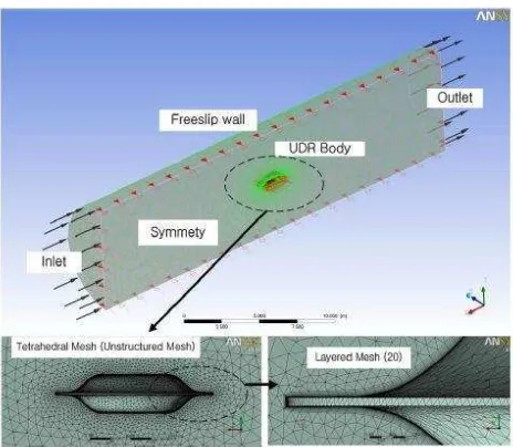
In 2012, Joung, T.H et al. [8] have done research on underwater disk robot (UDR) which designed as a disk shaped vehicle in order to minimize the effect of external disturbances such as currents and waves. In the research, CFD software, ANSYS-CFX is been used to evaluate the design by resistance, propulsion and motion test. These test required to predict the drag force propulsion and motion performance of the UDR. For the analysis on the shape of UDR body, the condition is set in a cylindrical shape water tank as the domain. The length of the tank was made long enough to observed the wake from the UDR body such Figure 2.2.
Figure 2.2: Review of the pre-processing and meshing results for the CFD analysis[8].
The design speed of the UDR in CFD model is at 3.5 knots@ 1.8004 m/s. The total drag force on the UDR body, composed of the friction drag force and the form drag force, was obtained by CFD analysis.
The research was continued in 2014 [9] with the same model which include new study in the effect of meshing on the converge study of the model performed at the same design speed which is 3.5 knots. The results are displayed in Table 2.2. It was observed that once the number of cells for the case is reached the size of the reference, the variation in the total drag force (RT) was small considering the significant changes
![Figure 2.1: Slave arm including a flexible joint driven by water pressure[6]](https://thumb-ap.123doks.com/thumbv2/123dok/495401.55128/23.595.231.448.71.224/figure-slave-including-flexible-joint-driven-water-pressure.webp)