ContentslistsavailableatSciVerseScienceDirect
Wear
j o ur n a l ho me p a g e :w w w . e l s e v i e r . c o m / l o c a t e / w e a r
Deformation–wear
transition
map
of
DLC
coating
under
cyclic
impact
loading
Mohd
Fadzli
Bin
Abdollah
a,∗, Yuto
Yamaguchi
a, Tsuyoshi
Akao
b, Naruhiko
Inayoshi
c,
Nobuyuki
Miyamoto
c,
Takayuki
Tokoroyama
a,
Noritsugu
Umehara
aaDepartmentofMechanicalScienceandEngineering,GraduateSchoolofEngineering,NagoyaUniversity,Furo-cho,Chikusa-ku,Nagoya464-8603,Japan bTechnologyPlanningDepartment,DENSOCorporation,1-1Showa-cho,Kariya-shi,Aichi448-8661,Japan
cMaterialsEngineeringR&DDepartment,DENSOCorporation,1-1Showa-cho,Kariya-shi,Aichi448-8661,Japan
a
r
t
i
c
l
e
i
n
f
o
Articlehistory:
Received18May2011 Receivedinrevisedform 24November2011 Accepted28November2011
Available online 6 December 2011
Keywords:
Impacttesting DLCcoating
Deformation–weartransitionmap Impactwearmechanisms
a
b
s
t
r
a
c
t
Anewdeformation–weartransitionmapofhydrogen-freeamorphouscarboncoating(commonlyknown asDiamond-LikeCarbon(DLC)coating)ontungstenhighspeedsteel(SKH2)substrateundercyclicimpact loadinghasbeenproposedtoclarifytheinteractionsoftheoperatingparameters,deformationandwear. Thestudywascarriedoutusinganimpacttester,underlubricatedconditionsoverawiderangeofimpact cycles,andappliednormalloads.SKH2discswerecoatedwiththinDLCfilmsusingaPhysicalVapor Deposition(PVD)method.Tungsten(W)wasusedasaninterlayermaterial.TheDLCcoateddiscwas impactedrepeatedlybyachromiummolybdenumsteel(SCM420)pin.Allimpacttestswereconducted atroomtemperature.Ithasbeensuggestedthatthedeformation–weartransitionmapisaneasyway toillustratetheimpactwearmechanismsofDLCcoating,asshownbyitstransitionzones.Initially,the DLCcoatingonlyfollowstheplasticdeformationofthesubstrateuntilseveralimpactcycles.Then,a suppressionofplasticdeformationofthesubstrateistakingplaceduetothedecreasingcontactpressure withimpactcyclestotheyieldpoint.WearoftheDLCcoatingbecomesdominantwhenthecriticallimit ofmaximumnormalimpactloadandimpactcyclesisexceeded.Fromexperimentalobservations,some degradationoftheDLCcoatingoccurswithinthewearzone.
© 2011 Elsevier B.V. All rights reserved.
1. Introduction
DLChasattractedgreatattentionformanyapplicationsdueto itstremendousproperties,suchashighhardness,thermalstability, lowfrictioncoefficient,andgoodchemicalinertness.Furthermore, theDLCfilmshowedanexcellentwearresistanceindryand water-or oil-lubricatedconditions [1].The useof DLCcoating,onthe impactsurfacesofcomponents,provideshighlevelsofprotection againstsurfacedamage.
Theconceptofa‘wearmap’wasfirstdiscussedbyTabor[2], andwasinspiredbythepioneeringworkofFrost[3]on ‘defor-mationmaps’.Thedevelopmentofdeformation–weartransition mapisausefulwaytostudyandpredictthetransitionof deforma-tiontowearofonematerialimpactingagainstanotheratdifferent loadsandcycles.Furthermore,thelocationsofthetransitionzones
∗Correspondingauthor.Tel.:+81527892788;fax:+81527892788.
E-mailaddresses:[email protected](M.F.B.Abdollah),
[email protected](Y.Yamaguchi),
[email protected](T.Akao),[email protected]
(N.Inayoshi),[email protected](N.Miyamoto),
[email protected](T.Tokoroyama),[email protected]
(N.Umehara).
withintheoperatingparametersareimportant,inordertodesign engineerlesscomponentfailuresoccurringprematurely.
Generally, the construction of transition maps follows two routes[4,5].Oneisempirical:datafromexperimentsareplottedon suitableaxesandidentifiedbywearrateorobservationand bound-ariesaredrawntoseparateclassesofbehavior.Theotherrouteis thatofphysicalmodeling:model-basedequations,describingthe wearratecausedbyeachmechanism,arecombinedtogiveamap showingthetotalrate,andthefieldofdominanceofeach.However, onlytheempiricalapproachisusedinthisstudy.
Theweartransitionmapsspecifictocertainmaterials,suchas ceramics[6],greycastiron[7],magnesiumalloy[8],brassalloy
[9], silicon nitrite [10], have been developed extensively for a decade.Allthetransitionmaps,whichappearintheabovestudies, wereconstructedusingeitheraphysicalmodelingoranempirical approachbasedontheslidingtestdata.However,inthiscentury, thereisstillnodevelopmentofdeformation–weartransitionmap oftheDLCcoatingundercyclicimpactloading.Therefore,theaimof thisstudyistoproposeanewdeformation–weartransitionmapof DLCcoatingbasedonvariationsofmaximumnormalimpactloads andimpactcycles.Afterashortdescriptionoftheimpacttestused inthisstudy,theconstructionofthedeformation–weartransition mapwillbepresentedusingexperimentaldataandobservations. Thetransitionmapof DLCcoating,undercyclicimpactloading,
0043-1648/$–seefrontmatter© 2011 Elsevier B.V. All rights reserved.
tendstofocusonthedescriptionofitsimpactwearmechanisms andthetransitionbetweenthem.
2. Experimentalmethod
2.1. Materials
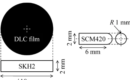
TheSKH2discwasusedasasubstrate,whilstSCM420pinwas usedasanimpactor.Thediameterofthediscandthepinwere 10mmand2mm,respectively(asshowninFig.1).AllDLCfilms weredeposited onto the SKH2 substrate using a PVD method; whereWwasusedasaninterlayermaterial.Thefilmthicknesshc
isapproximately2.97m.TheaveragesurfaceroughnessRaofthe
as-depositedDLCcoatingisapproximately18.63nm,whichwas measuredbyAtomicForceMicroscopy(AFM).Materialproperties arelistedinTable1.
2.2. Impacttesting
Theimpacttestwasperformedusingtwoself-developedimpact testers,asshowninFig.2.Thehorizontalimpacttesterwasused formorethan102impactcycles,withafrequencyof10Hz;anda
drop-weightimpacttesterwasusedforthelowimpactcycles. TheimpacttestrigwasdesignedtoimpactaDLCcoateddisc withaSCM420pinfornumerousimpacts.Priortotheimpacttest, bothdiscandpinwerecleanedusingacetoneinanultrasonicbath. TheDLCcoateddiscwasrepeatedlyimpactedata90◦inclination
atroomtemperature.Severaldifferentmaximumnormalimpact loadswereappliedtotheDLCcoateddiscviaaspringsystemforthe horizontalimpacttester.Meanwhile,themaximumnormalimpact loadofthedrop-weightimpacttestercouldbeincreasedbyadding animpactormassm.Ithasbeenreportedthattheimpactormass doesnotsignificantlyaffectimpactperformances(deformationand wear)[11,12].Theappliedloadwasobservedbyaloadcell.
ThesurfacemorphologyoftheaffectedareaontheDLC coat-ing,aswellasonthecounterpartmaterial,wasobservedbyAFM, FieldEmissionScanningElectronMicroscopy(FE-SEM),andEnergy DispersiveX-raySpectroscopy(EDS).Inaddition,theFocusedIon
Fig.1. DimensionsoftheDLCcoateddiscandtheSCM420pin.
Table1
MaterialpropertiesoftheDLC,SKH2substrateandSCM420pin.
Properties DLC SKH2 SCM420
Youngmodulus,E(GPa) 251 378 295
Poisson’sratio,v 0.3 0.3 0.3
Hardness,H(GPa)a 17.14 9.80 7.43
Yieldstrength,Y(GPa)b 6.12 3.50 2.65
aFromthenanoindentationtest. b Y=H/2.8.
Fig.2. Schematicillustrationoftheimpacttester:(a)horizontalimpacttesterand (b)drop-weightimpacttester.
Beam(FIB)wasusedtomillthetestedsample,inordertoexamine thecrosssectionoftheDLCcoatingontheSKH2substrate.
2.3. Residualimpactcratervolume/depth
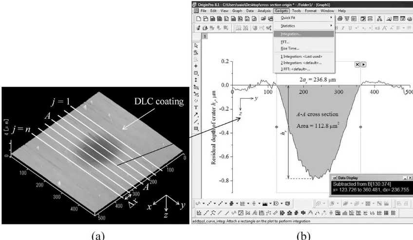
Therawdatacollectedincludedthemeasurementsofthe resid-ualimpactcratervolumeanditsdepth/radius.Thedepthhrand radiusaroftheresidualimpactcrateroftheDLCcoatingwere mea-sureddirectlyfromacross-sectionalAFMtopographyimage.The cross-sectionalimage,paralleltothey-axis,wastakenatthecenter ofimpactcrater,asshowninFig.3.Inordertocalculatetheresidual impactcratervolume,rawdatafromtheAFMwasexportedto Orig-inPro8.1.Anillustrationofhowtheresidualimpactcratervolume wascalculatedisshowninFig.3.Therawdataofx-axiswere dis-cretetoncross-sectionswiththethicknessofx.ThesurfaceareaA
ofeachcross-sectionwasdeterminedusingtheintegrationmethod functioninOriginPro8.1.TheresidualimpactcratervolumeVris determinedusingthefollowingequation:
Vr= n−1
j=1
(A×x)j (1)
2.4. Transitionofcontactpressure
Fig.3.(a)Discretionsofx-axisofanimpactcratertoncrosssections,withthethicknessofxand(b)determinationofeachsurfacearea(A–Acrosssection)usingthe integrationfunctioninOriginPro8.1.
(a)Contactconditionisassumedtobepointcontact.
(b) Themajor(y)axisandminor(x)axisoftheresidualcontact radius,obtainedexperimentallyfromeachimpactcycle,isused.
Meancontactpressurepmeanforiimpactcyclesiscalculatedby usingthefollowingequation[14]:
pmean,i= Fz
arxary
i(2)
whereFzisthemaximumnormalimpactload,aryandarxarethe residualradiiofthemajorandminoraxes,respectively.
2.5. Wearmeasurements
InordertodeterminetheweardepthoftheDLCcoating,its crosssectionontheSKH2substratewaspreparedusingaFIBand observedbyFE-SEM,asshowninFig.4.Thetestedsamplewas milledalongthecentreoftheimpactcraterofthemajoraxis.From
Fig.5,itisassumedthattheweardepthhw(measuredfromthe FIB-milledcross-sectionalimage)isconstantthroughoutthecontact surface,andthus
hp=hr−hw (3)
wherehp istheplasticdeformationdepthandhristheresidual depthofimpactcrater.
Fig.4.FE-SEMcross-sectionalviewoftheFIB-milledDLCcoatingontheSKH2substrate(tiltedat60◦),whereh60c1isthenon-impactedfilmthickness,andh60c2isthe
Fig.5.Schematicillustrationoftheweardepthhw.
2.6. Constructionofthedeformation–weartransitionmap
Inthisstudy,theconstructionofthedeformation–wear transi-tionmapisacombinationofproceduresbyAshbyandLim[5]and ShuandShen[6].
Nouniversaldeformation–weartransitionmapexists,because thecontrollingvariables differfrom mechanism tomechanism. Therefore,suitableaxesofthemaphavetobedecided.Inthisstudy, theappropriateaxesaredeterminedtobethemaximumnormal impactloadFzandtheimpactcyclesN.Thesevariableswere cho-senfortworeasons:firstly,theydirectlydeterminetheresidual impactcratervolumeandsecondly,theyareunderthecontrolof theoperator,andeasilymeasured.
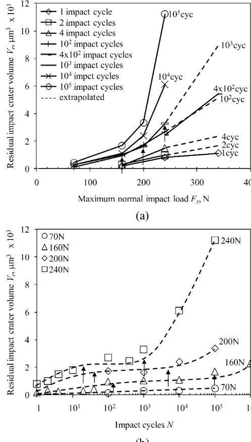
Alldata points of the residual impact crater volume Vr are plottedasfunctionsofFz andN,asshowninFig.6.Some
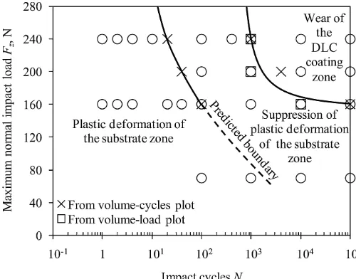
inter-polations and extrapolations are needed to obtain an evenly distributeddataset.Then,thelocationsofbothload-andimpact cycle-dependentdeformation–weartransitions,areidentifiedby experimentalobservationsanddatatrendanalysis.Arrowsindicate theonsetofthesevariable-dependentdeformation–wear transi-tions.Thebestfittingcurvesconnectingallofthetransitionpoints arethentracedandillustratedinthegraphofFzvs.N,asshown inFig.7.Thesecurvesrepresentthedeformation–weartransition boundaryoftheimpactedDLCcoating.
3. Resultsanddiscussion
3.1. Deformation–weartransitionmap
Themaximumnormalimpactloadandimpactcyclesareboth importantparametersandeithervariablecaninduceatransition from deformation to wear of DLC coating, as shown in Fig. 6. Therefore,adeformation–weartransitionmapwasgeneratedby simultaneouslyvarying the maximum normal impact load and impactcycles,whichrevealedthistransitionverywell.
Besides,theimpactwearmechanismsoftheDLCcoatingcan easilybeshownbyitstransitionzonesonthedeformation–wear transitionmap,asshowninFig.7.Threezoneswereidentified:
(a)Theplasticdeformationofthesubstratezone,wherethe resid-ualimpactcratervolumechangeswiththemaximumnormal impactloadandimpactcycles.Asdemonstratedinprevious experiment[12],thedeformationofanelastic-perfectplastic substrateshouldnotbealteredbythepresenceofathinfilm, whichitselfsimplyfollowsthedeformationofthesubstrateat theinterface.Thestraininthefilmisgovernedbythesurface strainofthesubstrate.Furthermore,Fig.8clearlyshowsthat almostnowearisobservedat70and160Nofthemaximum normalimpactload.Inaddition,theweardepthisalmostzero
Fig.6.ResidualimpactcratervolumeoftheimpactedDLCcoating,plottedasa functionof(a)maximumnormalimpactloadand(b)impactcycles.(Arrowsindicate theonsetofload/cycle-dependentdeformation–weartransitions.)
at200and240Nunderlowimpactcycles.Thisthereforereveals thatonlyplasticdeformationofthesubstratehasoccurred. (b)Suppressionofplasticdeformationofthesubstratezone,where
theresidualimpactcratervolumeremainsconstantwiththe impactcycles. Thisisduetothedecreasingcontactpressure withimpactcyclestotheyieldpoint,asshowninFig.9.Asthe numberofimpactcyclesisincreased,thecontactareaspreads. Additionally, thisexperiment wasunder theconstant maxi-mumnormalimpactloadforeachimpactcycle,andtherefore, thecontactpressureisdecreased.Inthiszone,thedeformation ofsubstrateismostlikelytoundergoanelasticdeformation ifthecontactpressure isalmostorbelowitsyieldpoint.By increasingthemaximumnormalimpactload,thesuppression ofplasticdeformationofthesubstratetakingplace,isfaster.At 240Nofmaximumnormalimpactload,theplasticdeformation ofthesubstrateissuppressedafter101impactcycles,because
Fig.7. Deformation–weartransitionmapofDLCcoatingundercyclicimpact load-ing.Theillustrationofthepredictedboundaryisbasedonthecontactpressure approachingtheyieldpoint.
Fig.8.Comparisonoftheresidualdepthoftheimpactcraterhrandtheplastic deformationdepthhpasafunctionoftheimpactcycles.Thedifferencebetween bothcurves(patternedinverticallines)givestheapproximateweardepthofthe DLCcoating.
Fig.9. Relationshipbetweenmeancontactpressureandimpactcycles.
reason.Thepredictedboundary,showninFig.7,isillustrated basedonthecontactpressureapproachingtheyieldpoint. (c)WearoftheDLCcoatingzone,wheretheresidualimpactcrater
volumeincreasesrapidly/radicallywiththemaximumnormal impact loadand impact cycles. A critical maximum normal impactloadandacriticalimpactcycleexiststhatwill precipi-tatetheweartransitionoftheDLCcoating.Moreover,atthose criticalimpactloadsand impactcycles,weargraduallyrises asmaterialiswornaway.Fig.8showsthatnowearoccursif themaximumnormal impactloadisvery small,buta wear transitionoccurs(duetotheimpactcycles)whenthe maxi-mumnormalimpactloadreachesabove160N.Generally,the presenceofatransferlayeronthecounterpartmaterialafter repeatedimpactsmodifiesthetribologicalcontactfromthatof SCM420/DLCtoDLC/DLC;anda significanttemperaturemay resultatthecontactpointduetothelowthermal conductiv-ityofDLC,thuspromotinggraphitization.Inaddition,interface failurescanbefound,wherethecoatinglosesadhesiontothe substrateduetobothshearandtensilestress[15].Cracksmay startfromdefectsattheinterfaceandsometimescause catas-trophic failure withdelamination of ratherbig flakesof the coating.Iftheloadishighenough,cohesivefailuresandfatigue can alsobefound[15].The cohesivefailuresnormally con-sistofacontinuousremovalofthecoating,startingfromthe middleofthesphericalcalotte.Thefatigueoccursdueto peri-odicalstressloadsandshowsmicro-crackswithinthecoating. Consequently,theincreaseinwear,asthemaximumnormal impactloadandimpactcyclesisincreased,maybeduetothe combinationofgraphitizationandcrackingfromcyclicimpact loading.Thisisinagreementwiththisstudy,wheresome degra-dationoftheDLCcoating,suchascrackpropagationofthefilm, phasetransformation,andatribochemicalreactionofthewear debris/transferlayer,wasobserved.Inaddition,theformation ofatransferlayerontheaffectedareaofthecounterpart mate-rialwasalsoobservedexperimentallyinthiszone.Detailsabout thiswearwillbebrieflydiscussedinSection3.2.
3.2. DegradationofDLCcoatingwithinthewearzone
3.2.1. Crackpropagation
Asthethinhardcoatingfullytransmitstheimpactgenerated stressfieldtotheductilesubstrate,thesubstrateundergoesalarge
Fig.11.FE-SEMmicrographoftheweardebristakenfromtheedgeofimpactcrater. Thetop-leftmicrographisanimpactcrater.
plasticdeformation(largeindentdepth)thatthecoatingcannot accommodateotherthanbydevelopinganetworkofcracks.Radial crackscan therefore beobserved in theDLCfilm, as shown in
Fig.10.Thismicrographhasbeentakenafter104 impactcycles
at240N,usingFE-SEM.Radialcrackingisobservedinthecoating belowtheimpaction,which initiatesfromthecoating/substrate interface and propagates upwards into the coating. The main reason for this is the low yield stress of the substrate, which allowedplastic strainunder theimpactor; which the hard and oftenbrittlecoatingcouldnotfollow.Toreducethestressinthe coating,itstartstobuildaradialcrackinsidethecoating.Theradial cracksobservedinthisstudyhavealsobeenidentifiedinastudy onindentationandscratching[16].Tensilestressconcentrationsat
Fig.12.Ramanspectrumoftheweardebrisandtransferlayerafter104and105
impactcyclesat240N.TheRamanspectrumoftheas-receivedSCM420pinandthe as-depositedDLCcoatingareforcomparison.
thecoating/substrateinterfaceduringloadinghavebeenidentified asadrivingforcethatcausesthistypeofcrack[17,18].
3.2.2. Phasetransformationandtribochemicalreactionofwear debrisandtransferlayer
TheweardebrisoftheimpactedDLCcoatingwereonlyobserved ontheedgeoftheimpactcraters,asshowninFig.11.Inthecaseof acontinuouspresenceofoillubricant,thegenerateddebris com-binedwithoil,andremovedprogressivelybyitsevacuationoutside oftheimpactcraters.However,someoftheweardebristransferred tothecounterpartmaterial,asatransferlayer.Thegraphitization ofweardebris,aswellasthetransferlayer,isconfirmedbythe
Ramanspectroscopystudy[19].FromFig.12,theGpeakofthewear debrisshiftedtoahigherfrequencycomparedtotheas-deposited DLCcoating.Therefore,thismeansthatthesp2 bondingfraction
increases,partialtetrahedralbondshavebeenbroken,andhave transformedintotrigonalbonds[20].ThedecreaseintheFWHMG
indicatedtheremovalofabondangledisorderandthe increas-ingdominanceofcrystallites[20].Fromtheanalysisabove,thesp2
coordinatedcarbonbecomesgraduallydominantandcausesphase transformationfromsp3tosp2,whichwouldinducegraphitization.
Asforthetransferlayer,thegraphitizationisexpectedtooccur sinceitmainlycomesfromtheweardebris.Thisisconfirmedasthe Gpeakisshiftedtohigherfrequencythanthatoftheas-deposited DLCcoating,asshown in Fig.12.However,the wideningofits FWHMG,after105impactcyclesat240N,suggeststhatthesize
ofthelargersp2clustersisreducedduetothemechanicalcrushof
thelargersp2clusters.
Inaddition,thetribochemicalreactiontotheenvironment dur-ingimpactoccurredatthematingmaterialwherethetransferlayer adhered;aswellasintheweardebris[19].Thiswasduetothe oxi-dationofferrum(Fe)tomagnetite(Fe3O4)andhematite(␣-Fe2O3)
phaseswithapredominantpeakatapproximately680cm−1and
1317cm−1.Thebroadpeakatabout1350cm−1,whichis
proba-blyduetothedisorderedgraphite(Dpeak),overlappedwiththe
␣-Fe2O3peak.Thus,theDpeakisnotclearlyvisibleinFig.12.
3.2.3. Formationofthetransferlayer
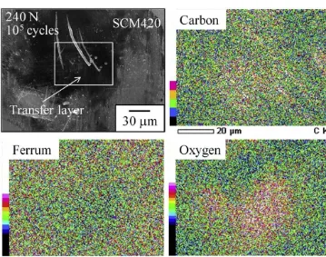
Undertribologicalconditions,thesofterofthetwomaterials willusuallybeworn.InthecaseofDLC,thissituationmaybe dif-ferentsincethewearofDLC,whichhasagraphiticnature,canbe depositedontothepartnersurface,formingtheso-calledtransfer layer.TheDLCthencontactsagainstitsowntransferlayerandeven thoughitisthehardersurface,onlytheDLCiswornataverylow wearrate,whereasthesofterpartnersurfacewillnotbeworn.The EDSmaps(asshowninFig.13)confirmthattheDLCcoating trans-ferredtothecounterpartmaterialofSCM420pinafter105impact
cyclesat240N.
4. Conclusions
Anewdeformation–wear transitionmap ofDLCcoating has beenproposedusingthetest resultstostudyofhowindividual impact parameters suchas maximum normal impactload and impactcyclesinfluencethistransition.
TheimpactwearmechanismsoftheDLCcoatingcaneasilybe shownbyitstransitionzonesonthedeformation–weartransition map.Threezoneshavebeenidentifiedasfollows:
(a)The plastic deformation of the substrate zone:the residual impact cratervolume increases with the maximum normal impactloadandimpactcycles.Onlythesubstrateisplastically deformed.Inaddition,wearhasnotbeenobservedinthiszone. (b)Suppression of plastic deformation of the substrate zone: theresidualimpactcratervolumeremainsconstantwiththe impactcyclesandplasticdeformationofthesubstratenolonger appears.Thisisduetothedecreasingcontactpressure with impactcyclestotheyieldpoint.
(c)WearoftheDLCcoatingzone:theresidualimpactcratervolume increasesrapidly/radicallywiththemaximumnormalimpact loadandimpactcycles,duetomaterialloss.TheDLCcoating appearstoapproachahighdegreeofwearwhenthecritical limit of maximumnormal impactloadand impactcyclesis exceeded.Thiswearisassociatedwithsomedegradationofthe DLCcoating,suchasthepropagationofradialcracksintheDLC film,phasetransformationoftheweardebris/transferlayer,and itstribochemicalreactionwiththeenvironment.Inaddition, formationofatransferlayeronthecounterpartmaterialhas alsobeenobservedexperimentallyinthiszone.
Acknowledgments
TheauthorMohdFadzliBinAbdollahgratefullyacknowledges thescholarshipfromUniversitiTeknikalMalaysiaMelaka(UTeM) forhisDoctoralstudy.
References
[1]K.Holmberg,H.Ronkainen,A.Matthews,Tribologyofthincoatings,Ceram.Int. 26(2000)787–795.
[2]D.Tabor,Statusanddirectionoftribologyasascienceinthe80s:understanding andprediction,in:Proc.Int.Conf.Tribol.80s,vol.1,1984,pp.1–17. [3]H.J.Frost, M.F. Ashby,DeformationMechanism Maps: ThePlasticityand
CreepofMetalsandCeramics,firsted.,PergamonPress,Oxford,NewYork, 1982.
[4] S.C.Lim,M.F.Ashby,Wear-mechanismmaps,ActaMetall.35(1987)1–24. [5]M.F. Ashby, S.C. Lim, Wear-mechanism maps, Scripta Metall.24 (1990)
805–810.
[6]S.M.Hsu,M.C.Shen,Ceramicwearmaps,Wear200(1996)154–175. [7] A.R.Riahi,A.T.Alpas,Wearmapforgreycastiron,Wear255(2003)401–409. [8]H.Chen,A.T.Alpas,SlidingwearmapforthemagnesiumalloyMg–9Al–0.9Zn
(AZ91),Wear246(2000)106–116.
[9]K.Elleuch,R.Elleuch,R.Mnif,V.Fridrici,P.Kapsa,Slidingweartransitionfor theCW614brassalloy,Tribol.Int.39(2006)290–296.
[10] J.R.Gomes,A.S.Miranda,J.M.Vieira,R.F.Silva,Slidingspeed-temperaturewear transitionmapsforSi3N4/ironalloycouples,Wear250(2001)293–298.
[11]P.Robinson,G.A.O.Davies,Impactormassandspecimengeometryeffectsin lowvelocityimpactoflaminatedcomposites,Int.J.Eng.12(1992)189–207. [12] M.F.B.Abdollah,Y.Yamaguchi,T.Akao,N.Inayoshi,T.Tokoroyama,N.
Ume-hara,Theeffectofmaximumnormalimpactload,absorbedenergy,andcontact impulseontheimpactcratervolume/depthofDLCcoating,Tribol.Online6 (2011)257–264.
[13] T.Yoshimi,S.Matsumoto,Y.Tozaki,T.Yoshida,H.Sonobe,T.Nishide,Work hardeningandchangeincontactconditionofrollingcontactsurfacewith plas-ticdeformation,Tribol.Online4(2009)1–5.
[14] K.L.Johnson,ContactMechanics,firsted.,CambridgeUniversityPress, Cam-bridge,1985.
[15]C.P.O. Treutler, Industrial use of plasma deposited coatings for compo-nentsofautomotivefuelinjectionsystems,Surf.Coat.Technol.200(2005) 1969–1975.
[16]Z.H.Xie,R.Singh,A.Bendavid,P.J.Martin,P.R.Munroe,M.Hoffman,Contact damageevolutioninadiamond-likecarbon(DLC)coatingonastainlesssteel substrate,ThinSolidFilms515(2007)3196–3201.
[17]A.C.Fischer-Cripps,B.R.Lawn,A.Pajares,L.Wei,Stressanalysisofelastic-plastic contactdamageinceramiccoatingsonmetalsubstrates,J.Am.Ceram.Soc.79 (1996)2619–2625.
[18]A.Abdul-Baqi,E.VanderGiessen,Numericalanalysisofindentation-induced crackingofbrittlecoatingsonductilesubstrates,Int.J.SolidStruct.39(2002) 1427–1442.
[19]M.F.B.Abdollah,Y.Yamaguchi,T.Akao,N.Inayoshi,N.Umehara,T.Tokoroyama, Phasetransformationstudiesonthea-Ccoatingunderrepetitiveimpacts,Surf. Coat.Technol.205(2010)625–631.