Auzani Bin Jidin
, Nik Rumzi Bin Nik Idris
, Abdul Halim Bin Mohamed
Yatim
, Senior Member, IEEE
, Malik E. Elbuluk
, Senior Member, IEEE
, and Tole Sutikno
, Student Member, IEEE
Abstract—This paper presents a simple overmodulation method
employed in direct torque control (DTC) constant switching fre-quency (CSF) controller of induction machines. The proposed over-modulation method is utilized to extend a constant torque region and hence produce high torque capability in field-weakening re-gion with six-step operation. It will be shown that the overmod-ulation operation using the DTC-CSF scheme can be established by controlling the stator flux locus from circular to the hexag-onal shape. This is achieved by modifying the flux error status produced from the flux hysteresis controller before it is fed to the lookup table. The main benefit of the proposed method is its simplicity since it requires only a minor modification to the con-ventional DTC hysteresis-based structure and does not require a space-vector modulator.
Index Terms—Direct torque control (DTC), field weakening,
in-duction machine, overmodulation.
I. INTRODUCTION
T
HE capability of induction machine drives to operate in overmodulation and field-weakening modes is very im-portant in many industrial applications. It is desirable in order to achieve high constant power or the maximum torque capabil-ity over a wide speed range of operation.Several papers have been published [1]–[14] proposing other types of solutions for achieving maximum torque capability in field-weakening region. The most common approach adopted is to estimate the optimal flux level of the motor based on the max-imum values of inverter voltage and inverter current. Typically, the algorithms used require frame transformer, knowledge of machine parameters, and space-vector modulator. For example,
Manuscript received June 24, 2010; revised November 8, 2010, February 27, 2011, and September 5, 2011; accepted September 6, 2011. Date of current version February 27, 2012. Recommended for publication by Associate Editor F. Blaabjerg.
A. B. Jidin, N. R. B. N. Idris, A. H. B. M. Yatim, and T. Sutikno are with the Department of Energy Conversion, Universiti Teknologi Malaysia, Skudai, 81310 Johor, Malaysia (e-mail: [email protected]; [email protected]; [email protected]; [email protected]).
M. Elbuluk is with the Department of Electrical and Computer En-gineering, University of Akron, Akron 44325-3904 OH USA (e-mail: [email protected]).
Color versions of one or more of the figures in this paper are available online at http://ieeexplore.ieee.org.
Digital Object Identifier 10.1109/TPEL.2011.2168240
Sang-Hoon and Seung-Ki [3] used field-oriented control space-vector modulation (FOC-SVM) that considers voltage and cur-rent limit conditions to compute the controllable curcur-rents (in stator flux reference frame) in achieving the appropriate flux level in field-weakening region. Other papers have reported a robust field-weakening strategy, so that any variations of ma-chine parameters used in calculating the optimal flux, can be compensated [5], [9], [11], [14].
In general, the SVM technique is employed to exploit the in-verter voltage into the overmodulation region where the voltage reference is normally used to define the mode of overmodu-lation [15]. The ability of SVM to fully utilize the available inverter voltage mainly depends on the vector control strat-egy to produce the maximum possible voltage reference while simultaneously maintaining the regulation of flux and torque. Various methods have been proposed to estimate the voltage reference [13], [16]–[22]; for instance, in the case of direct torque control (DTC)-SVM, Tripathiet al.[17] utilized predic-tive control of stator flux error vector to estimate the reference voltage. Habetleret al.[16] used dead-beat control, with several complicated equations, to generate the reference voltage in real time. Among the various schemes only [12] and [13] can achieve maximum torque capability in field-weakening region with six-step voltage operation. In [12], due to the hexagonal shape of the stator flux locus, the current contains low-frequency harmonic components even when the drive is operating in steady-state con-dition. On the other hand, Tripathiet al.[13] achieved the six-step mode operation through overmodulation using SVM. Ulti-mately, all of the proposed methods [13], [16]–[18], [21], [22] complicate the basic control structure of DTC drive systems as originally proposed in [23].
Until now, no study has been reported to carry out the over-modulation strategy in DTC hysteresis-based structure mainly due to the fact that in DTC hysteresis-based structure, unlike the DTC-SVM, there is no voltage reference available. This paper presents a simple overmodulation strategy employed in DTC constant switching frequency (CSF)-based induction ma-chines. The control structure of DTC-CSF is similar to the DTC hysteresis-based scheme [36], which does not use SVM and, hence, does not have the voltage vector reference to oper-ate in overmodulation modes [15]. However, unlike the DTC-hysteresis-based scheme, DTC-CSF can be operated with CSF. It will be shown in this paper that even without SVM, the
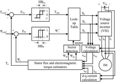
Fig. 1. Structure of basic DTC-hysteresis-based induction machine.
inverter voltage can be gradually transformed from pulsewidth modulation (PWM) to six-step mode by changing the stator flux locus from circular to hexagonal shapes. In this way, an exten-sion of constant torque region can be achieved which results in higher torque capability in field-weakening region. By us-ing this technique, it is also possible for the drive to operate in six-step mode during acceleration (and deceleration) and revert back to the PWM mode when steady-state condition is reached, for beyond based speed operation. In Section II, the DTC with constant frequency torque controller is briefly discussed. Sec-tion III explains the torque capability in DTC and describes how the overmodulation is achieved based on stator flux locus transformation. Section IV presents improved torque capability with the proposed overmodulation strategy. Section V describes the proposed control structure. Section VI presents the hard-ware implementation and experimental results of the proposed method. Finally, the conclusion is given in Section VII.
II. DTC WITHCSF SCHEME
Unlike FOC, the DTC scheme as shown in Fig. 1, offers a simple control structure wherein the torque and flux can be separately controlled using three-level and two-level hysteresis comparators, respectively. The output of the comparators and the stator flux angle are used to index a lookup table of optimum voltage vector as proposed in [23], to determine the appropriate voltage vectors to control both torque and flux. However, the hysteresis torque controller utilized in the basic DTC structure results in two major disadvantages, namely variable inverter switching frequency and high torque ripple. Several methods have been proposed to overcome these problems. For example, the problems were minimized by the use of variable hysteresis band [24], [25], dithering technique [26], controlled duty ra-tio cycle technique [27], [28], space-vector modulara-tion (DTC-SVM) [21], [29]–[31], and most recently the use of predictive control [32]–[35].
An attempt was made to reduce the torque ripple by replac-ing the torque hysteresis controller with constant frequency torque controller as depicted in Fig. 2 [36]. In such a way, the
Fig. 2. Constant frequency torque controller.
Fig. 3. Comparison by experimental of torque control operations in (a) DTC-hysteresis-based and (b) DTC-CSF-based induction motor.
simple control structure (with decoupled control structure) of hysteresis-based DTC is retained. For the sake of identification, in this paper, this scheme will be referred to as DTC-CSF. The torque error statusTstat(as shown in Fig. 2) generated from the
constant frequency torque controller to compensate the torque errorETe can be described by
Tstat =
1 for Tc ≥Cupp er
0 for Clower< Tc< Cupp er
−1 for Tc≤Clower (1)
whereTcis the output of proportional-integral (PI) control and
Cupp erandClowerare the upper and lower triangular carriers,
re-spectively. In order to establish CSF and, hence, reduced torque ripple, the frequency and peak to peak of upper and lower trian-gular waveforms are set at fixed values. For PI torque controller, the gain values ofKpandKiare restricted to ensure the absolute
slope of the output signal, andTcdoes not exceed the absolute
slope of triangular carrier [36].
the torque ripple of the DTC hysteresis-based, one can ideally reduce the hysteresis band. This may lead to the incorrect volt-age vector selections (whereTstat =−1) that will cause rapid
decreases in output torque and hence increases the torque ripple instead of reduces it [36].
III. TORQUECAPABILITY INDTC
The behavior of induction machine in DTC drives can be described in terms of space vectors by the following equations written in stator flux reference frame
vs=rsis+jωsΨs+d Ψs
dt (2)
0 =rrir+j(ωs−ωr)Ψr+
dΨr
dt (3)
Ψs=Lsis+Lmir (4)
Ψr=Lrir+Lmis (5)
Te =3 4p
Lm
σLsLr
ΨsΨrsinδsr (6)
where p is the number of poles, δsr is the angle between the
stator flux and rotor flux vectors, ωs is the stator flux angular
frequency,ωris the rotor angular speed,Ls,Lr, andLm are the
motor inductances, andσis the leakage coefficient. The leakage coefficientσis given as
σ= 1− L
2 m
LsLr
. (7)
In practice, a rated stator flux and inverter current limit (i.e., 150–200% of rated current machine) are used to obtain the maximum torque capability. The maximum output torque can be retained as long as the operation of rotor speed does not exceed its base speed. According to (6), the angle δsr plays
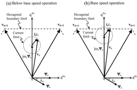
Fig. 4. Phasor diagrams at particular flux position for (a) low-speed operation and (b) high-speed operation.
a vital role in controlling the output torque. Since the angle
δsrmainly depends on the slip angular frequency (ωs−ωr), to
maintain the output torque to its maximum value, the slip angular frequency (ωs−ωr) must always be kept at its maximum value.
This is typically established for speeds below the base speed. Fig. 4 shows the phasor diagrams of (2) under steady-state conditions for operations below base speed [see Fig. 4(a)] and at base speed [see Fig. 4(b)]. For each case, the same magni-tude of stator flux vector is used and the vectors are drawn in stator fluxd–qreference frame. In the case of low-speed oper-ation, the back-emf,jωsΨs is small enough such that sufficient
stator voltage can be generated to control both stator flux and torque, simultaneously. At base speed [see Fig. 4(b)], the stator voltage vector touches the hexagonal stator voltage boundary limit. Hence, there are two options to further increase the speed beyond the base and at the same time maintain the maximum torque capability.
1) Weaken the flux (in normal practice to be inversely pro-portional with speed), so that the magnitude of the vector
jωsΨs is retained as the frequency increases. However, thedcomponent of the stator current will be reduced. Un-der this condition, the average stator voltage will stay on the hexagonal boundary and the stator flux is regulated using two active voltage vectors. This is what happens in the DTC hysteresis-based drive where the flux locus is circular and no overmodulation is exploited in the stator voltage.
2) Operate the inverter in overmodulation mode; thus, the average stator voltage will go beyond the hexagonal boundary limit. In normal practice, to obtain the maximum voltage vector (i.e., six-step mode), the voltage vector ref-erence of the SVM is modified [15]. Once the six-step volt-age is reached, to further increase the speed, the flux will have to be weakened. This method can be performed for the DTC based on SVM. This method cannot be applied in DTC hysteresis-based drive because no stator voltage reference is available to implement the overmodulation. Basically both methods will ensure that (ωs −ωr) is kept to
increased. As the speed is increased, a more tangential voltage vector is selected; hence, higher stator flux angular speed is achieved. In the second method, the zero-voltage vector is also not used. The angular speed of the stator flux is increased since instead of alternating between two vectors, a single voltage vector is gradually applied as the waveform gradually changes from PWM to six-step mode. The flux will only be weakened once the six-step voltage is reached. This means that in the second method, the constant torque region is extended since the voltage capability is increased.
The previous discussion indicates that the control of maxi-mum torque for a wider speed range is very much related to the ability to extend the limit of stator flux angular frequency or the stator voltage limit. In this paper, a method that uses an overmod-ulation strategy is proposed. However, unlike other modovermod-ulation strategies, which used SVM (the second method), the proposed method is based on the DTC hysteresis-based structure, which contains no voltage vector reference.
IV. IMPROVEDTORQUECAPABILITYWITH THEPROPOSED
OVERMODULATIONSTRATEGY
This section presents the proposed overmodulation strategy to improve capability of torque over a wide speed range opera-tion. The method is different from the SVM-based system where the reference stator voltage is available and overmodulation is achieved by modifying the reference voltage. With no reference voltage available in DTC-CSF, the overmodulation is accom-plished by gradually transforming the PWM voltage waveform to six-step mode, which is achieved by transforming the shape of the stator flux locus from circular to the hexagonal shapes. Since DTC-CSF uses the same structure as the DTC hysteresis-based, the control structure is simple yet CSF and reduced torque rip-ple can be achieved without the need of SVM. This section will first discuss how the PWM to six-step mode operation is ac-complished by shaping the stator flux locus without resolving to DTC-SVM-based drive. Next, the operation in field-weakening mode using the proposed overmodulation is described.
A. Extending the Stator Voltage Operation to Six-Step Mode
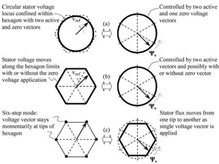
In the SVM-based system, the overmodulation starts when the reference voltage vector goes beyond the stator voltage hexagonal trajectory. The reference voltage will be modified whenever it goes outside the hexagonal limits [15]. If the mod-ified reference voltage moves along the hexagonal trajectory, the synthesized voltage will have no zero-voltage vector. In DTC hysteresis-based drive, zero-voltage vectors will not be selected when the actual (or estimated) torque does not reach the reference torque. In order to fully utilize the dc voltage, the stator voltage magnitude has to go beyond this limit and operate in six-step mode. However, with the conventional hysteresis-based structure DTC drive, this is not possible. With regard to the stator flux locus, when the reference voltage is sinusoidal, i.e., within the hexagon, the locus of the stator flux is circu-lar [see Fig. 5(a)]. As a matter of fact, when the stator voltage vector trajectory moves along the hexagon without any zero-voltage vector application, the stator flux locus is still circular
Fig. 5. Mapping of the voltage vector and the stator flux trajectories.
[see Fig. 5(b)]. This is because without the zero vectors, the stator flux is still regulated by the two active vectors and, hence, will follow the circular locus reference, with limited stator volt-age and angular flux frequency. To go around this problem, what we need to do is to modify the output of the stator flux hysteresis comparator, so that the selected voltage vector will transform stator voltage to six-step waveform.
In the proposed overmodulation strategy, the stator flux locus is controlled to form the hexagonal shape during motor acceler-ation. By doing so, lower harmonic components in stator current due to the hexagonal flux locus and six-step operations occur but only during acceleration (or deceleration). The proposed control structure to establish the hexagonal flux locus utilizing DTC-CSF will be explained in Section V. When the motor accelerates, the back-emf increases; therefore, larger stator voltage is needed to satisfy the torque demand. The demand will be naturally ful-filled by the controller that will gradually drop the applications of zero-voltage vectors as the speed increases. As the speed is further increased and no more zero-voltage vector is available, the selection of voltage vector will naturally transform to six-step mode [see Fig. 5(c)]. In other words, by transforming the stator flux locus to the hexagonal shape, we provide the room for the stator voltage to increase beyond the hexagonal bound-ary and the torque demand will naturally transform the stator voltage from PWM to six-step mode.
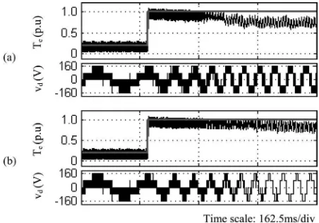
Fig. 6 depicts the simulation results to compare the perfor-mance of stator voltage and torque capability for DTC-CSF with and without the proposed overmodulation strategy. The values of the machine and parameter systems used for both cases are given in Table I. As can be seen, a smooth transition of stator voltage from PWM to six-step mode is achieved with the proposed over-modulation strategy and hence extending the constant torque region.
B. Flux Weakening With Six-Step Mode
Fig. 6. Comparison of the performances of stator voltage and torque capability for (a) DTC-CSF without the proposed overmodulation and (b) DTC-CSF with the proposed overmodulation.
Fig. 7. Operational control of the locus and magnitude of stator flux.
conventional flux-weakening method (in order to retain the sim-ple control structure) but with a minor modification. Using the proposed method, the magnitude of the hexagonal stator flux is inversely proportional to the rotor speed when the motor oper-ates beyond the base speed,ωbase,hex. However, a step reduction
of 13.4% in the flux magnitude is applied as the hexagonal flux locus is immediately changed back into the circular locus when the motor speed reaches its target (steady-state speed). The op-erational control of locus and magnitude of stator flux can be described as illustrated in Fig. 7. This reduction ensures that the output torque can be well regulated to its reference. In fact, higher level of flux reference (which for this case is without a step reduction), particularly at very high speed operations, gives insufficient stator flux angular frequency (or appropriate slip) which may degrade the output torque control, as discussed in [1]. The reference of flux is given as
Ψs,ref = Ψs,ratedωbase,hex
ωm
(1−α.cos (π/6)) (8) whereΨs ,rated is the stator flux rated andαis used to activate the step reduction whenαequals 1 otherwise it is 0.
V. PROPOSEDCONTROLSTRUCTURE
Fig. 8 shows the control structure of DTC-CSF with the pro-posed overmodulation strategy. Notice that all components of the DTC hysteresis-based scheme are retained, except for the inclusion of the “modification of flux error status” block which
Fig. 8. Structure of DTC-CSF-based induction machine with the proposed block of modification of flux error status.
Fig. 9. Proposed digital outputs for modified flux error status corresponding to the flux positions (subsector in every sector).
is responsible for the overmodulation mode by transforming the stator flux locus from circular to hexagon. For speed control op-eration, the torque referenceTe ,ref is generated from a PI speed
controller and the reference of flux is calculated using (8) in flux weakening region or it is held at rated flux in constant torque region. The locus of stator flux is controlled to form a hexago-nal shape when the motor operates under acceleration condition (i.e., by inspecting the error of rotor speedEω) by modifying
the flux error status (Ψ+
s) to a new flux status (Ψ−s) before it is
being fed to the lookup table.
The proposed digital outputs of the modified flux error status
Ψ−
s (to perform hexagonal flux locus) according to flux positions
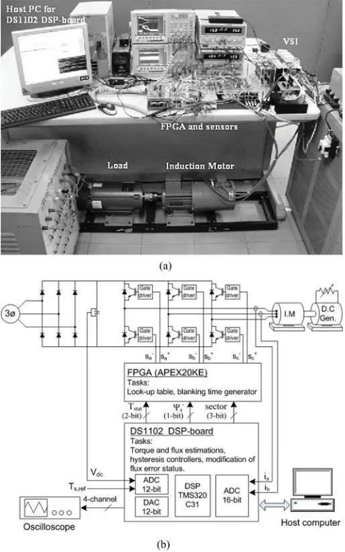
Fig. 10. Complete drive system. (a) Picture of the experiment setup. (b) Func-tional block diagram of the experiment setup.
This will be repeated as the flux moves to a different sector and as a result, the stator flux locus will become hexagonal. As the flux travels from one tip to another, zero vectors will be alternately selected between the active voltage vectors. However, as the rotor speed increases, less zero vector duration will be generated, and thus, this will ensure the stator flux frequency is increased to maintain the maximum torque capability.
VI. IMPLEMENTATION ANDEXPERIMENTALRESULTS
To verify the feasibility of the proposed overmodulation and flux weakening strategy, a complete drive system, as shown in Fig. 10, has been realized. The experimental setup consists of an insulated gate bipolar transistor inverter and a 1.5-kW, four-pole squirrel cage induction motor. The actual parameters of an induction motor and parameters for the hysteresis-based DTC and CSF-based DTC drives are shown in Table I. For safety reasons, the dc voltage was limited to 240 V, which means that the based speed is reduced to 570 r/min. The control algorithm is
implemented on a dSPACE 1102 controller board and an Altera FPGA (APEX20KE) board. The sampling period of the DTC scheme, including the proposed overmodulation, is 55µs.
To investigate the performance of torque capability for a wide speed range operation, a step change of speed reference from 0.5 to 2.8 p.u has been carried out for five different schemes. For convenience of identification, these schemes are referenced as follows.
1) DTC1: conventional hysteresis-based DTC and conven-tional flux-weakening method [α=0 in (8)].
2) DTC2:the hysteresis-based DTC with the proposed over-modulation strategy and conventional flux-weakening method.
3) DTC3: the hysteresis-based DTC with the proposed over-modulation strategy with a step reduction of flux applied when the motor speed reaches its reference in flux weak-ening region [α=1 in (8)].
4) DSC:the hysteresis-based direct self control (DSC) as pro-posed in [12] and conventional flux-weakening method. 5) DTC-CSF2:the CSF-based DTC with the proposed
over-modulation strategy with a step reduction of flux ap-plied when the motor speed reaches its reference in flux-weakening region [α=1 in (8)].
Fig. 11 shows the experimental results of motor torque, stator flux, motor speed, and stator phase voltage when the step change of reference speed is applied in DTC1, DTC2, and DTC3 (all schemes used hysteresis-based controller). From Fig. 11, it can be seen that the capability of output torque in DTC2 or DTC3 during the motor acceleration is higher than that obtained in DTC1 and hence gives faster motor acceleration. The proposed overmodulation strategy (utilized in DTC2 and DTC3), as dis-cussed in the previous section, provides an extension of constant torque region and allows the stator voltage to operate in com-plete six-step mode, particularly in flux weakening region. The extension of the constant torque region in Fig. 11 can be more clearly demonstrated through torque–speed curve, as depicted in Fig. 12, which shows the plot of torque versus speed obtained from Fig. 11. The figure indicates that the constant torque re-gion for DTC3 is increased by more than 10% when compared with DTC1. With the extension of the constant torque region, the torque capability during the field-weakening mode is also improved.
Fig. 11. Experimental results of output torque, stator flux magnitude, motor speed, and stator phase voltage when a step change of speed reference from 0.5 to 2.8 p.u is applied in (a) DTC1, (b) DTC2, and (c) DTC3.
Fig. 12. Experimental graph of torque–speed for (a) DTC1 and (b) DTC3 (corresponding to the results obtained in Fig. 11).
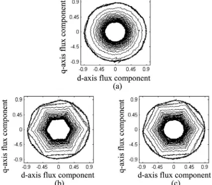
The operation of stator flux locus for DTC1, DTC2, and DTC3 corresponding to the results obtained in Fig. 11 are depicted in Fig. 14. It is apparent that the step reduction of flux magnitude proposed in DTC3 fits into the hexagonal flux locus as the motor speed reaches its reference. On the other hand, the magnitude of circular flux locus in DTC2, which is identical to the magnitude of hexagonal flux locus, gives a flux reference which is too high and hence causes poor performance of torque control at very high speed operation as shown in Figs. 11(b) and 13(b). From Fig. 14, it also can be noticed that the magnitude of the stator flux in DTC1 and DTC3 are the same as the motor speed reaches its reference.
Fig. 15 depicts the experimental results of motor torque, stator flux, motor speed, and stator current when the step change of reference speed is applied in DTC3, DSC, and DTC-CSF2. From Fig. 15, it can be observed that the capabilities of torque obtained
Fig. 13. Zoomed images (corresponding to the results obtained in Fig. 11) of stator phase voltage and output torque in (a) DTC1, (b) DTC2, and (c) DTC3.
Fig. 14. Comparison of stator flux locus obtained in (a) DTC1, (b) DTC2, and (c) DTC3.
Fig. 15. Experimental results of output torque, stator flux magnitude, motor speed, and stator current when a step change of speed reference from 0.5 to 2.8 p.u is applied in (a) DTC3, (b) DSC, and (c) DTC-CSF2.
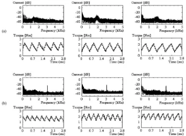
Fig. 16. Experimental results of phase current frequency spectrum and output torque for (a) basic DTC and (b) DTC-CSF at the speed of approximately 20, 30, and 55 rad/s.
even operating in steady-state conditions. As can be seen from Fig. 15(b), the stator current in DSC seems to have high THD (obviously as the motor speed runs at 0.5 p.u) since the flux locus is always hexagonal. In Fig. 15, it also can be noted that the DTC-CSF2 offers lower output torque ripple when the output torque is controlled at its reference.
Fig. 16 shows the frequency spectrum of the phase current obtained from the experimental results for the basic DTC and DTC-CSF at the speed of 20, 30, and 55 rad/s, while the out-put torque is controlled at 2 Nm. It can be seen that the phase current in DTC-CSF contains dominant harmonic at triangu-lar frequency (i.e., at 3.03 kHz) regardless of the speed, as
opposed to the DTC hysteresis-based which has a frequency spectrum which is spread out and depends on the operating speed.
VII. CONCLUSION
REFERENCES
[1] X. Xu and D. W. Novotny, “Selection of the flux reference for induction machine drives in the field weakening region,” IEEE Trans. Ind. Appl., vol. 28, no. 6, pp. 1353–1358, Nov./Dec. 1992.
[2] O. Wasynczuk, S. D. Sudhoff, K. A. Corzine, J. L. Tichenor, P. C. Krause, I. G. Hansen, and L. M. Taylor, “A maximum torque per ampere con-trol strategy for induction motor drives,” IEEE Trans. Energy Convers., vol. 13, no. 23, pp. 163–169, Jun. 1998.
[3] K. Sang-Hoon and S. Seung-Ki, “Maximum torque control of an induction machine in the field weakening region,” IEEE Trans. Ind. Appl., vol. 31, no. 4, pp. 787–794, Jul./Aug. 1995.
[4] S. Myoung-Ho, H. Dong-Seok, and C. Soon-Bong, “Maximum torque control of stator-flux-oriented induction machine drive in the field-weakening region,” IEEE Trans. Ind. Appl., vol. 38, no. 1, pp. 117–122, Jan./Feb. 2002.
[5] M. Mengoni, L. Zarri, A. Tani, G. Serra, and D. Casadei, “Stator flux vector control of induction motor drive in the field weakening region,”
IEEE Trans. Power Electron., vol. 23, no. 2, pp. 941–949, Mar. 2008. [6] S. Jul-Ki and S. Seung-Ki, “Optimal flux selection of an induction machine
for maximum torque operation in flux-weakening region,” IEEE Trans. Power Electron., vol. 14, no. 4, pp. 700–708, Jul. 1999.
[7] H. Grotstollen and J. Wiesing, “Torque capability and control of a saturated induction motor over a wide range of flux weakening,” IEEE Trans. Ind. Electron., vol. 42, no. 4, pp. 374–381, Aug. 1995.
[8] D. Casadei, G. Serra, and A. Tani, “Direct flux and torque control of induction machine for electric vehicle applications,” inProc. 7th Int. Conf. Electr. Mach. Drives, Sep. 1995, pp. 349–353.
[9] D. Casadei, G. Serra, A. Stefani, A. Tani, and L. Zarri, “DTC drives for wide speed range applications using a robust flux-weakening algorithm,”
IEEE Trans. Ind. Electron., vol. 54, no. 5, pp. 2451–2461, Oct. 2007. [10] H. Abu-Rub, H. Schmirgel, and J. Holtz, “Maximum torque production in
rotor field oriented control of an induction motor at field weakening,” in
Proc. IEEE Int. Symp Ind. Electron., Jun. 2007, pp. 1159–1164. [11] H. Abu-Rub, H. Schmirgel, and J. Holtz, “Sensorless control of induction
motors for maximum steady-state torque and fast dynamics at field weak-ening,” inProc. 41st IAS Annu. Meet. Conf. Record Ind. Appl. Conf., Oct. 2006, pp. 96–103.
[12] M. Depenbrock, “Direct self-control (DSC) of inverter-fed induction ma-chine,” IEEE Trans. Power Electron., vol. 3, no. 4, pp. 420–429, Oct. 1988.
[13] A. Tripathi, A. M. Khambadkone, and S. K. Panda, “Dynamic control of torque in overmodulation and in the field weakening region,”IEEE Trans. Power Electron., vol. 21, no. 4, pp. 1091–1098, Jul. 2006.
[14] G. Gallegos-Lopez, F. S. Gunawan, and J. E. Walters, “Current control of induction machines in the field-weakened region,” IEEE Trans. Ind. Appl., vol. 43, no. 4, pp. 981–989, Jul./Aug. 2007.
[15] J. Holtz, W. Lotzkat, and A. M. Khambadkone, “On continuous control of PWM inverters in the overmodulation range including the six-step mode,”
IEEE Trans. Power Electron., vol. 8, no. 4, pp. 546–553, Oct. 1993. [16] T. G. Habetler, F. Profumo, M. Pastorelli, and L. M. Tolbert, “Direct
torque control of induction machines using space vector modulation,”
IEEE Trans. Ind. Appl., vol. 28, no. 5, pp. 1045–1053, Sep./Oct. 1992. [17] A. Tripathi, A. M. Khambadkone, and S. K. Panda, “Stator flux based
space-vector modulation and closed loop control of the stator flux vector in overmodulation into six-step mode,” IEEE Trans. Power Electron., vol. 19, no. 3, pp. 775–782, May 2004.
[18] G. Griva, T. G. Habetler, F. Profumo, and M. Pastorelli, “Performance evaluation of a direct torque controlled drive in the continuous PWM-square wave transition region,” IEEE Trans. Power Electron., vol. 10, no. 4, pp. 464–471, Jul. 1995.
IEEE Trans. Power Electron., vol. 15, no. 4, pp. 769–777, Jul. 2000. [23] I. Takahashi and T. Noguchi, “A new quick-response and high-efficiency
control strategy of an induction motor,” IEEE Trans. Ind. Appl., vol. IA-22, no. 5, pp. 820–827, Sep. 1986.
[24] K. Jun-Koo, C. Dae-Woong, and S. Seung-Ki, “Direct torque control of induction machine with variable amplitude control of flux and torque hysteresis bands,” inProc. Int. Conf. Electr. Mach. Drives, May 1999, pp. 640–642.
[25] V. Ambrozic, G. S. Buja, and R. Menis, “Band-constrained technique for direct torque control of induction motor,” IEEE Trans. Ind. Electron., vol. 51, no. 4, pp. 776–784, Aug. 2004.
[26] T. Noguchi, M. Yamamoto, S. Kondo, and I. Takahashi, “Enlarging switch-ing frequency in direct torque-controlled inverter by means of ditherswitch-ing,”
IEEE Trans. Ind. Appl., vol. 35, no. 6, pp. 1358–1366, Nov./Dec. 1999. [27] S. Mir and M. E. Elbuluk, “Precision torque control in inverter-fed
in-duction machines using fuzzy logic,” inProc. 26th Annu. IEEE Power Electron. Spec. Conf., Jun. 1995, vol. 1, pp. 396–401.
[28] K. Jun-Koo and S. Seung-Ki, “New direct torque control of induction motor for minimum torque ripple and constant switching frequency,”
IEEE Trans. Ind. Appl., vol. 35, no. 5, pp. 1076–1082, Sep./Oct. 1999. [29] A. Tripathi, A. M. Khambadkone, and S. K. Panda, “Torque ripple analysis
and dynamic performance of a space vector modulation based control method for AC-drives,” IEEE Trans. Power Electron., vol. 20, no. 2, pp. 485–492, Mar. 2005.
[30] J. Rodriguez, J. Pontt, C. Silva, R. Huerta, and H. Miranda, “Simple direct torque control of induction machine using space vector modulation,”
Electron. Lett., vol. 40, pp. 412–413, 2004.
[31] D. Casadei, G. Serra, A. Tani, L. Zarri, and F. Profumo, “Performance analysis of a speed-sensorless induction motor drive based on a constant-switching-frequency DTC scheme,”IEEE Trans. Ind. Appl., vol. 39, no. 2, pp. 476–484, Mar./Apr. 2003.
[32] J. Beerten, J. Verveckken, and J. Driesen, “Predictive direct torque control for flux and torque ripple reduction,” IEEE Trans. Ind. Electron., vol. 57, no. 1, pp. 404–412, Jan. 2010.
[33] T. Geyer, G. Papafotiou, and M. Morari, “Model predictive direct torque control—Part I: Concept, algorithm, and analysis,” IEEE Trans. Ind. Electron., vol. 56, no. 6, pp. 1894–1905, Jun. 2009.
[34] G. Papafotiou, J. Kley, K. G. Papadopoulos, P. Bohren, and M. Morari, “Model predictive direct torque control—Part II: Implementation and experimental evaluation,” IEEE Trans. Ind. Electron., vol. 56, no. 6, pp. 1906–1915, Jun. 2009.
[35] G. Abad, M. A. Rodriguez, and J. Poza, “Two-level VSC based predictive direct torque control of the doubly fed induction machine with reduced torque and flux ripples at low constant switching frequency,”IEEE Trans. Power Electron., vol. 23, no. 3, pp. 1050–1061, May 2008.
[36] N. R. N. Idris and A. H. M. Yatim, “Direct torque control of induction machines with constant switching frequency and reduced torque ripple,”
IEEE Trans. Ind. Electron., vol. 51, no. 4, pp. 758–767, Aug. 2004.
Auzani Bin Jidin(M’07) received the B.Eng. and M.Eng. degrees in electrical engineering from Uni-versiti Teknologi Malaysia, Skudai, Malaysia, in 2002 and 2004, respectively, and where he is cur-rently working on the Ph.D. degree.
Nik Rumzi Bin Nik Idris(M’97–SM’03) received the B.Eng. degree in electrical engineering from the University of Wollongong, Wollongong, Australia, the M.Sc. degree in power electronics from Brad-ford University, BradBrad-ford, West Yorkshire, U.K., and the Ph.D. degree from Universiti Teknologi Malaysia, Skudai, Malaysia, in 1989, 1993, and 2000, respectively.
He was a Visiting Research Associate at the Uni-versity of Akron, Akron, OH, in 2002. Currently, he is an Associate Professor at the Universiti Teknologi Malaysia. His research interests include ac drive systems and digital signal pro-cessing applications in power electronic systems.
Dr. Idris is an Administrative Committee Member of the Industry Appli-cations Society, Power Electronics Society, and Industrial Electronics Society Joint Chapter of IEEE Malaysia Section.
Abdul Halim Bin Mohamed Yatim(M’89–SM’01) received the B.Sc. degree in electrical and elec-tronic engineering from Portsmouth Polytechnic, Portsmouth, U.K., in 1981, and the M.Sc. and Ph.D. degrees in power electronics from Bradford Univer-sity, Bradford, U.K., in 1984 and 1990, respectively. Since 1982, he has been a member of the Faculty at the Universiti Teknologi Malaysia, Skudai, Malaysia, where he is currently a Professor and Deputy Dean of the Faculty. He has been involved in several research projects in the areas of power electronic applications and drives. He was a Commonwealth Fellow during 1994–1995 at Heriot-Watt University, Edinburgh, U.K., and a Visiting Scholar at the Virginia Power Elec-tronics Center, Virginia Polytechnic Institute and State University, Blacksburg, in 1993.
Dr. Yatim is a Corporate Member of the Institution of Engineers Malaysia. He is a Registered Professional Engineer with the Malaysian Board of Engi-neers. He currently holds the Interim Chapter Chair of the Malaysian Section of the IEEE Industrial Electronics/Industry Applications/Power Electronics Joint Societies.
Malik E. Elbuluk(S’79–M’79–SM’97) received the B.Sc. (Hons.) degree from the University of Khar-toum, KharKhar-toum, Sudan, and the M.S., E.E., and D.Sc. degrees from the Massachusetts Institute of Technology, Cambridge, in 1976, 1980, 1981, and 1986, respectively, all in electrical engineering.
He is currently a Professor at the University of Akron, Akron, OH, where he has been since 1989. He was with the Faculty of the Department of Elec-trical and Computer Engineering and the Electric Power Research Center, North Carolina State Uni-versity, from 1986 to 1989. He was a Summer Research Fellow at NASA Lewis Research Center, Cleveland, OH, from 1991 to 2000. His work at NASA in-cluded low-temperature electronics for space missions, modeling and simulation of the Space Station Freedom, the power by wire, the power electronic build-ing blocks, and the starter/generator for aircraft engines and sensorless control of electromechanical actuators for the more electric aircraft. His teaching and research interests include the areas of power electronics, electric machines, con-trol systems, fuzzy logic, and neural networks.
Prof. Elbuluk actively publishes and reviews papers for IEEE Conferences and Transactions, and has organized and chaired a number of sessions for the Power Electronics, the Industry Application, and the Industrial Electronics So-cieties. He was an Associate Editor for the IEEE TRANSACTIONS INPOWER
ELECTRONICSand is currently the Manufacturing Systems Development and Applications Department Vice President for the IEEE TRANSACTIONS ONIN
-DUSTRYAPPLICATIONSand also the Vice President and Technical Program Chair for the Industry Automation and Control Committee. He is a Registered Profes-sional Engineer in the Ohio.
Tole Sutikno (M’07) received the B.Eng. degree in electrical engineering from Diponegoro Univer-sity, Semarang, Indonesia, the M.Eng. degree in power electronics from Gadjah Mada University, Yo-gyakarta, Indonesia, in 1999 and 2004, respectively. He is currently working toward the Ph.D. degree in the Department of Energy Conversion, Universiti Teknologi Malaysia, Skudai, Malaysia.