CONVEYOR DESIGN FOR DISPOSAL SYSTEM
NORAINA BINTI MAJID
This report is submitted in partial fulfillment of the requirement for the award of Bachelor of Electronic Engineering (Industrial Electronic) With Honours
Faculty of Electronic and Computer Engineering Universiti Teknikal Malaysia Melaka
ii
UNIVERSTI TEKNIKAL MALAYSIA MELAKA
FAKULTI KEJURUTERAAN ELEKTRONIK DAN KEJURUTERAAN KOMPUTER
BORANG PENGESAHAN STATUS LAPORAN
PROJEK SARJANA MUDA II
Tajuk Projek : CONVEYOR DESIGN FOR DISPOSAL SYSTEM
………
mengaku membenarkan Laporan Projek Sarjana Muda ini disimpan di Perpustakaan dengan syarat-syarat kegunaan seperti berikut:
1. Laporan adalah hakmilik Universiti Teknikal Malaysia Melaka.
2. Perpustakaan dibenarkan membuat salinan untuk tujuan pengajian sahaja.
3. Perpustakaan dibenarkan membuat salinan laporan ini sebagai bahan pertukaran antara institusi
pengajian tinggi.
4. Sila tandakan ( ) :
SULIT*
(Mengandungi maklumat yang berdarjah keselamatan atau kepentingan Malaysia seperti yang termaktub di dalam AKTA RAHSIA RASMI 1972)
TERHAD* (Mengandungi maklumat terhad yang telah ditentukan oleh organisasi/badan di mana penyelidikan dijalankan)
TIDAK TERHAD
Disahkan oleh:
__________________________ ___________________________________
(TANDATANGAN PENULIS) (COP DAN TANDATANGAN PENYELIA)
Alamat Tetap: 45-C PARIT WAHID BAKRI BATU 5
84200 MUAR JOHOR
iii
I declare that this thesis entitled “Conveyor Design For Disposal System” is the result of my own research except as cited in the references. The thesis has not been accepted for any degree and is not concurrently submitted in candidature of any other degree.
iv
“I hereby declare that I have read this thesis and in my opinion this thesis is sufficient in terms of scope and quality for the award of Bachelor of Electronic Engineering (Industrial Electronics) With Honours”
v
vi
ACKNOWLEDGEMENTS
First and foremost, I would like to thank God upon his bless until I will be able to complete this project that called Conveyor Design For Disposal System to fulfill my Projek Sarjana Muda. I would like to take this opportunity to express my deepest appreciation and thanks to those who help in accomplishing my final year project. Without their help, the completion of this project will not be possible. I would like to express my sincere thanks to my family who have give me encouragement, support and the strength to keep moving on no matter what the odds and obstacles is ahead. I would like to give them thanks for none of this could have happened without them. A special thanks to my supervisor, Puan Siti Huzaimah Binti Husin for her support and guidance she has while the whole project and thesis writing was carries out. Without her continued support and interest, this thesis would not have been the same as presented here. Besides that, I would like to thanks to all lectures in UTeM especially FKEKK that are involved to giving their information, opinion and suggestion in my project
vii
ABSTRAK
viii
ABSTRACT
ix
TABLE OF CONTENTS
CHAPTER CONTENT PAGE
PROJECT TITLE i
RECOGNITION iii
SUPERVISOR RECOGNITION iv
x
II LITERATURE REVIEW
2.1 Introduction 6
2.2 Studying About Waste Disposal 7 2.3 Statistic about Waste Disposal 7 2.4 Analysis the Waste Disposal System in 8
Condominium Building
2.5 Conveyor chain at industry 11 2.5.1 Overview of Model 400 Material Mover 11
III THEORY OF COMPONENTS
3.2.1 Operation of The Motor Window 17 3.2.1.1 Part in Motor Power Window 18
3.3 Limit Switch 19
3.3.1 Normally Open 20
3.3.2 Normally Closed 20
3.3.3 Implementation To The Project 21 3.3.3.1 Implement to Real Application 21
xi
3.5 Indicator Lamp 23
3.6 Buzzer 24
3.7 Push Button Switch 25
3.8 Hardware Implementation 26
3.8.1 Frame of Model 26 4.2.3 Combining Hardware and Software 34
V PROGRAMMABLE LOGIC CONTROLLER
5.1 Introduction 36
5.2 Parts of a PLC 37
5.3 Principles of Operation 39
xii 6.2.1 Description of The System 50
6.3 Hardware Design 52
6.3.1 Project Model Layout 52 6.3.1.1 Dimension Of The Frame 52 6.3.1.2 Dimension Of The Chain 54 6.3.1.3 Dimension Of The Rail 55 6.3.1.4 Dimension Of The Smaller Bin 58
6.4 PLC Programming 61
6.4.1 Grafcet 61
6.4.2 Ladder Diagram 62
6.5 Conveyor Design For Disposal System Model 65
6.6 Discussion 66
VII CONCLUSION & RECOMMENDATION
7.1 Conclusion 68
xiii
REFERENCES 70
APPENDIXES A 71
APPENDIXES B 73
APPENDIXES C 75
APPENDIXES D 77
APPENDIXES E 80
APPENDIXES F 82
xiv
LIST OF FIGURES
FIGURE TITLE PAGE
Figure 1.1 Block Diagram of PLC 2
Figure 1.2 PLC OMRON 2
Figure 2.1 Analysis of household waste composition 8 Figure 2.2 The location of waste disposal at flat or 9
condominium area
Figure 2.3 The location of waste disposal 10 Figure 2.4 The rubbish was scattered around the dust bin 10
Figure 2.5 The Model 400 Material Mover 11 Figure 2.6 The Conveyor System That Used In Industry 12
Figure 3.1 The motor 14
Figure 3.2 The Direction of motor rotation 15 Figure 3.3 The main part of DC motor 15
Figure 3.4 Power Windows Motor 17
Figure 3.5 Motor And Electronics Subsystem 19 Figure 3.6 Structure while Not Function 20
Figure 3.7 Structure While Function 20
Figure 3.8 Structure While Not Function 20
Figure 3.9 Structure While Function 21
Figure 3.10 The Limit Switch 21
Figure 3.11 Relay 22
xv
Figure 4.1 Project Flowchart 30
Figure 4.2 Hardware Flow Chart 31 Figure 4.3 Software Flow Chart 33 Figure 4.4 Combining Hardware and Software 34
Figure 5.1 PLC OMRON 37
Figure 5.2 The System of PLC 38
Figure 5.3 Illustration of a Scan 40
Figure 5.4 The Connection of PLC Programmer to PLC 41
Figure 5.5 A Simple Relay Controller 44
Figure 5.6 Ladder Diagram 42
Figure 5.7 Grafcet 43
Figure 5.8 Grafcet and Ladder Diagram 44 Figure 5.9 Initial Internal State Graphical Symbol Using
Grafcet 44
Figure 5.10 Internal State Graphic Symbols 45 Figure 5.11 Transition Between Two Internal States 45
Figure 5.12 Mnemonic code 46
Figure 6.1 The Block Diagram of The Project System 50
Figure 6.2 The Project Design 50
Figure 6.3 Conveyor Design For Disposal System 51 Figure 6.4 The Measurement of The Project Model 53 Figure 6.5 Measurement of The Chain That Weld With
xvi
Figure 6.6 Side View of The model 55
Figure 6.7 The Measurement of Rail 55
Figure 6.8 The Wiring That Looping Of All Limit Switch 57 Figure 6.9 Connections Between Rail and Cable Break 57
Figure 6.10 Measurement of The Smaller Bin 58 Figure 6.11 Side View Measurement of The Smaller Bin 59
Figure 6.12 Three Dimensions (3D) Measurement of The
Smaller Bin 59
Figure 6.18 Ladder Diagram After Simulation By Using
PLC OMRON. 64
xvii
LIST OF TABLES
TABLE TITLE PAGE
Table 6.1 The Measurement of Frame Model 53
xviii
LIST OF APPENDIXES
NO TITLE PAGE
A Gantt Chart 71
B Poster 73
C Ladder Diagram 75
D Simulation By Using Cx-Programmer and PLC 77
E Mneumonic Code 80
F The Model 400 Material Movers In Action 82
xix
LIST OF ABBREVIATION
PLC - Programmable Logic Controller CPU - Central Processing Unit
DC - Direct current AC - Alternating Current PC - Personal Computer
SWM - System Waste Management EPA - Environmental Protection Agency
NC - Normally Open
CHAPTER I
INTRODUCTION
1.1 Introduction Of The Project
Toward to the globalization era, various equipment was created to make life easier. The effect from that, many aspects were undergone the changing in the latest technology to fill the goal. So, it includes the house equipment. Mostly, the consumer can find the new alternative to make the work easier. More rubbish will produce by human everyday. So, many dust bins was prepared at whole place for convenience and the country cleaning. But the waste disposal system at condominium or flat have a problem while the people just throw out the rubbish from the top and it may cause the rubbish to break and mess at that area. This project will aim to improve the waste disposal system at the condominium or flat area.
2
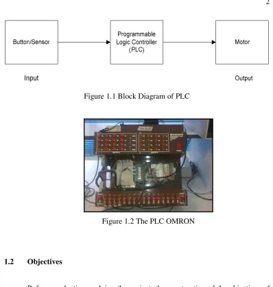
Figure 1.1 Block Diagram of PLC
Figure 1.2 The PLC OMRON
1.2 Objectives
Before conducting or doing the project, the construction of the objectives of the project is the main focus in this project. At the last of this report in the conclusion chapter the objective will be stated where it succeed or not. This project is purposely design to improve the waste disposal system at the flat of condominium building. It is because, the main objective of this project is to ascertain the garbage disposed will directly enter the trash can without scattering away even though it is thrown from higher floors.
3
This project also to keep the uninvited and wild animals away from residential area. For example, it can keep the dog or cat since looking the food at the heap of rubbish. Besides that, to reduce man labour used for cleaning purposes and it can save labour cost in long run.
1.2 Problem Statement
Each of the projects has their own problem to be discussed before starting the project. By realizing the problem statement it easy to know the purpose of doing this project and what are the problem to be solved. Nowadays, the waste disposal system at the flat or condominium building has a major problem where is the garbage that thrown from above like second or third level is very likely to tear apart and scatter when it reaches ground. Besides that, the surrounding area whereby the trashcan is located would be too dirty with wastes scattered around and it also producing unpleasant odours. In fact, the state of the area would cause an outbreak of diseases to the residents that live at that area.
The waste disposal system in flat or condominium building also has the problem which is the scattering rubbish would invite wild animal that are looking for rood. For example, the dog or cat would come looking for the food at the scattering rubbish. This also would cause an unwanted disturbance to the residential area. In order to maintain a clear, trash controlled area, cleaners are needed. A continuous cost is needed to wire labours for cleaning the trashed area.
4 1.4 Scope of Project
This project is based on electrical, electronics and mechanical application. The system is an application of a conveyor that uses a motor and chain for the navigation. The designed model has 2 level/floors where the ground floor stores the main disposal bin and smaller moves bins are installed on every level. These cans will be moved are along the levels by a navigator. Each bin must be fills up to 0.5kg of garbage and can be modified according to the real application. The whole weight capacity of the model is around a total of 2kg per bin.
For the model construction, Programmable logic controller (PLC) is used as a control device for the system. Among the items will be used in this project are chains, spocket, bearing, shaft, motor and aluminum bin. The bin will be attached to a chain and will be moved by a motor. Besides that, the electronic display will be used to display the indicator that needed. Limit switch is used in this project and act as sensor to detect the rubbish and to ON the motor.
1.5 Thesis Layout
This thesis is divided into seven chapters and summary of each chapter is briefly discussed in this section.
i) Chapter I
This chapter is given the reviews of the project background and objective as well as the project scope.
ii) Chapter II
5 iii) Chapter III
This chapter discusses the theory of the project that consists the several types of sensors and material usually been used in building the hardware implementation.
iv) Chapter IV
This chapter is the overview of the Programmable Logic Controller
v) Chapter V
This chapter describes the project methodology including the flow chart of the process.
vi) Chapter VI
This chapter discussing on experimental, results and analysis including the mechanical design.
v) Chapter VII