LINE DETECTING MOBILE ROBOT FOR DELIVERING AND RECEIVING LOADS TO DIFFERENT SET POINTS
CHAN SENG KIONG
LINE DETECTING MOBILE ROBOT FOR DELIVERING AND RECEIVING LOADS TO DIFFERENT SET POINTS
CHAN SENG KIONG
This Report Is Submitted In Partial Fulfillment of Requirements For The Degree of Bachelor In Electrical Engineering (Control, Instrumentation, and Automation)
Faculty of Electrical Engineering Universiti Teknikal Malaysia Melaka
“I hereby declared that I have read through this report and I found that it has comply the partial fulfillment for awarding the degree of Bachelor of Electrical Engineering
(control, instrumentation, and automation)
Signature : ..………..
Supervisor’s name : ………
“I hereby declared that this report is a result of my own work except for the excepts that have been cited clearly in the references.”
Signature : ………..
Name : ………..
Date : ………..
iii
Special dedication to my loving parents, Mr. Chan Pak Kim and Mrs. Yong Mui Chai, all my siblings, my kindhearted supervisor Mr. Ahmad Zaki bin Hj Shukor and thanks
ACKKOWLEDGEMENT
v
ABSTRACT
ABSTRAK
vii
TABLE OF CONTENTS
CHAPTER TITLE PAGE
SUPERVISOR DECLARATION
PROJECT TITLE i
DECLARATION ii
DEDICATION iii
AKNOWLEDGMENT iv
ABSTRACT v
ABSTRAK vi
TABLE OF CONTENTS vii-x
LIST OF TABLES xiii
LIST OF FIGURES xiv-xvii
1 INTRODUCTION
1.1 Introduction 1
1.1.1 What is a robot? 2
1.1.2 An Autonomous Robot 3 1.1.3 Application of Robot 3-4
1.2 Objective 4
1.3 Problem Statement 4
2 LITERARUTE REVIEW
2.1 Introduction 6
2.2 Background Study on Line Following Robot 7 2.2.1 Project sample 1: Two inexpensive line
tracking sensors for the MIT Handy Board
Microcontroller 7
2.2.1.1 Prototype Assembly 7-8
2.2.1.2 Comparison between 8-9
IR and LEB/CDs photocell
Line sensor 9-10
2.2.2 Project Sample 2: Desktop line
Following robot 10
2.2.2.1 About line follower 10
2.2.2.2 Hardware 11
2.2.2.2.1 Mechanical part 11-12 2.2.2.2.2 Electronic part 12-13 2.2.2.3 Using photo-reflectors 13-14 2.2.2.4 Signal Processing of line detection 15 2.2.2.5 Tracking Control 16-17
2.3 Microcontroller 17-18
2.3.1 Why Use Microcontroller? 18-19 2.3.2 Overview of microcontroller from Microchip 20 2.3.3 Why Use PIC18F4550 Microcontroller 20-21
2.4 Sensor 21
2.4.1 Infrared sensor 22-24
ix
2.4.1.3 Triangulation configuration 23-24 2.4.2 How Infrared Sensor work 24
2.5 Motor driver: L293B 25-26
2.5.1 Application Information for L293B 26 2.6 Analog-to-digital converter (ADC) 27
2.7 DC Motor 27
3 METHODOLOGY
3.1 Introduction 28
3.2 Project Methodology 29-30
3.3 Hardware
3.3.1 PIC USB burner 31-33
3.3.2 Microcontroller Board (16F877A 33-37
3.3.2.1 Port Assignment 37
3.3.3 Sensor circuit 38-39
3.3.4 Set Point Switch Circuit 39
3.3.5 Power Supply 40-41
3.4 Software
3.4.1 MikroC Programming 42-45
3.4.2 Proteus Professional 6 45-47
3.4.3 WinPIC800 47-51
4 FINAL RESULT
4.1 Introduction 52
4.2 Electrical and Electronic Development 53
4.2.1 Microcontroller Board 53
4.2.3 Sensor Circuit 55
4.2.4 Set Point Switch 56
4.2.5 Robot Structure 56-58
4.2.6 Robot Flow Plant 58-59
4.3 Software Development
4.3.1 Program for the Line Following Robot 60 4.4 Analysis
4.4.1 Failure of Circuit Board with USB PIC
Programmer and Microcontroller 61-62 4.4.2 Problem Occurs at Junction Counting 63 5 CONCLUSION
5.1 Introduction 64
5.2 Conclusion 64
5.3 Recommendation and Future Planning 65
REFERENCES 66
APPENDIX A 67
APPENDIX A-1 68-79
APPENDIX B 80-85
APPENDIX C 86-89
xi
LIST OF TABLE
NO TITLE PAGE
LIST OF FIGURES
NO TITLE PAGE
1.1 Robot compared to human 2
2.1 Spacing of emitter and collector 7
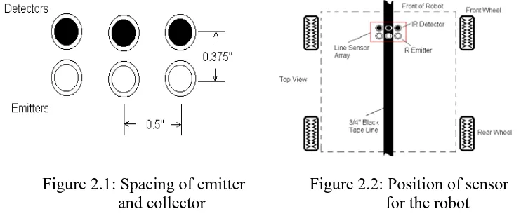
2.2 Position of sensor for the robot 7
2.3 Detector/emitter added isolate 8
2.4 Distance between sensors and floor 8 2.5 The line following robot for IR and LED/Cds
Photocell sensors comparison 9
2.6 Bottom and side view of the Desktop line following robot 11 2.7 Electrical circuit diagram for desktop line following robot 13 2.8 Function of photo reflector with or without ambient light 14 2.9 Graph actual line position Vs detected line position 15 2.10 Position of sensors between sensors and distance
Between sensors and floor 15
2.11 Tracking control using PID control 17
2.12 Microcontroller-Based 18
2.13 Pin Diagram of Microcontroller PIC16F877A 21 2.14 The common Strategies of IR sensor 22 2.15 Different Angles with Different Distances 23 2.16 Operation of Infrared Reflective Sensor 24
xiii
2.18 Motor driver L293B 25
2.19 DC Motor Controls (With connection to ground and
to the supply voltage) 26
2.20 Bidirectional DC Motor Control 26
3.1 Project flow chart 1 29
3.2 Project flow chart 2 29
3.3 USB PIC programmer circuit 31
3.4 USB PIC Programmer 32
3.5 USB PIC burner with 2 selections 33
3.6 PIC 86F877A 34
3.7 Block diagram of microcontroller board 35
3.8 Arrangement of 4 sensors 38
3.9 Sensors circuit 39
3.10 Set point switch circuit 39
3.11 Block diagram of 5V Power Supply to Microcontroller 40 3.12 Block diagram of 9V power supply to DC motor 40 3.13 1.5V GP Nickel Metal Hydride AA battery x 12pieces 41 3.14 Software MikroC open the new project 43
3.15 Step setting up the project 43
3.16 Example writing the program 44
3.17 Example of build project 45
3.18 Proteus Professional 6 Software 46
3.19 Place the HEX file into the microcontroller PIC 16F877 47
3.20 PIC16F877A detected 49
3.22 Program burning process 50
3.23 Program burning process success 51
3.24 Verifying PIC after burning process 51
4.1 Microcontroller board 53
4.2 Motor Driver 54
4.3 Sensor board (inverter) get signal from sensors and
send to microcontroller board 55
4.4 Sensors board 55
4.5 Set Point Switch 56
4.6 Base structure double gear box and wheel 56
4.7 Robot base structure 57
4.8 Robot structure without basket for deliver purpose 57 4.9 Robot structure with basket for deliver purpose 58
4.10 Flow plant 59
4.11 Circuit diagram of a board with USB programmer
and microcontroller 62
1
CHAPTER 1
INTRODUCTION
1.1Introduction
1.1.1 What is a robot?
According to Robot Institute of America (1979):
“A robot is a reprogrammable, multifunctional manipulator designed to move material, parts, tools, or specialized devices through various programmed motions for the performance of a variety of tasks”.
According to Webster dictionary:
“A robot is an automatic device that performs functions normally ascribed to humans or a machine in the form of human (Webster, 1993).”
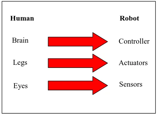
Generally, robots have three main parts known as processor, sensor, and motor control system. There are quite similar when comparing human with robot, only the mechanism is different. Sensor of the robot can represent eyes, while actuators represent the legs and controller as the brain as shown in Figure 1.1.
Human Robot
Brain Legs
Eyes
[image:18.595.179.432.411.594.2]Controller Actuators Sensors
3
1.1.2 An Autonomous Robot
Autonomous robots are robots which can perform desired tasks in unstructured environments without continuous human guidance. A high degree of autonomy is particularly desirable in fields such as space exploration, where communication and delays and interruptions are unavoidable.
A fully autonomous robot in the real world has the ability to gain information about the environments and work for months or years without human navigation assistance. Furthermore, it can avoid situation that are harmful to human, property or itself and repair without outside assistance.
1.1.3 Application of Robot
Robot can replace human’s job in industry because robot can do many things faster than humans. Robots do not need to be paid, eat, drink, or go to the bathroom like human. They can do repetitive work that is absolutely boring to human and they will not stop, slow down, or fall asleep like human.
Individual stationary sensors have limited ranges and applications. Watchdogs or human can lose their level of alertness during a shift or can easily be injured by an intruder. Autonomous robot systems are tools which combine the precision of sensors with the mobility and intelligence of humans. Robotic site security sentries are able to work long hours at a consistently high level of precision and vigilance.
Nowadays, doctors have to use a robot instead when operating. A human would not be able to make a hole exactly one 100th of a inch wide and long. When making medicines, robots can do the job much faster and more accurately and delicate than a human. Some doctors and engineers are developing prosthetic (bionic) limbs by using robotic mechanisms.
to their human operators. The continuing development of autonomous robot technologies furthers our abilities to explore the universe.
Beside that, robot can be applied in military operations to reduce the number of casualties which occur during military actions. The military also uses robots for locating and destroying mines on land and in water, entering enemy bases to gather information and spying on enemy troops.
1.2 Objective
The objectives of this project are:
1. To construct a prototype of mobile robot.
2. To construct a prototype controller board.
3. To integrate controller with robot body and sensors for line following.
4. To program the robot to detect destination point when called.
5. To navigate to destination points via knowledge base.
1.3 Problem Statement
5
1.4 Scopes of Project
1. The prototype robot able to follow line to deliver load and receive load to different set point, and able to making decision at junction. 2. The robot is design to function in indoor environment.
3. The robot is design to deliver light weight load such as document.
CHAPTER 2
LITERATURE REVIEW
2.1 Introduction
7
2.2 Background Study on Line Following Robot
A line following robot is one of self operating robot that follows the line that drawn on the floor. The movement of the robot is controlled by a programmed microcontroller. Programmer has to ‘teach’ the robot how to follow the line drawn on floor. A few samples of line following robots will be discussed in this chapter.
2.2.1 Project sample 1: Two inexpensive line tracking sensors for the MIT Handy Board Microcontroller.[8]
This project is comparing two types of inexpensive and simple line tracking sensor for line following robot which uses the MIT Handy Board microcontroller. The design of these sensors is somewhat general and can easily be adapted to other microcontrollers, such as Bot Board by Marvin Green, Parallalax Basic Stamps and others. The first sensor presented is infrared based, while the second one uses a red LED and a Cds photocell.
2.2.1.1 Prototype Assembly
[image:23.595.129.500.608.762.2]Position the sensors on a small PCB with the spacing shown in figure below. This recommended spacing works well for ¾’’ width tape lines.
Figure 2.1: Spacing of emitter and collector
The heat shrink tubing was added to isolate each detector/emitter pair to increase sensitivity.
The sensor should be rides between 1/16’’ to 1/8’’ above the ground
2.2.1.2 Comparison between IR and LED/CDs photocell line sensor
[image:24.595.242.413.157.283.2]A comparison was made between the IR and LED/CDs photocell line sensor. Both sensors were easy to construct and cost about the same amount, however; the IR sensor outperformed the LED/CDs version because of two observed reasons: larger sensor output range and robustness. First, the output of the IR sensor showed higher contrast between black and near white surfaces, i.e., had more range
Figure 2.3: Detector/emitter added isolate.
[image:24.595.221.392.392.534.2]