i
“ I hereby declare that I have read through this report entitle “Design and Develop The Spectacle Type Supporting Device For Visually Impaired Person” and
found that it has comply the partial fulfilment for awarding the degree of Bachelor of Mechatronics Engineering”.
Signature : ...
Supervisor’s Name : EN ANUAR BIN MOHAMED KASSIM
ii
DESIGN AND DEVELOP THE SPECTACLE TYPE SUPPORTING DEVICE FOR VISUALLY IMPAIRED PERSON
YONG KUEN WEI
A report submitted in partial fulfilment of the requirements for the degree of Bachelor of Mechatronics Engineering
Faculty of Electrical Engineering
UNIVERSITI TEKNIKAL MALAYSIA MELAKA
iii
I declare that this report entitle “Design and Develop the Spectacle Type Supporting Device for Visually Impaired Person” is the result of my own research except as cited in
the references. The report has not been accepted for any degree and is not concurrently submitted in candidature of any other degree.
Signature : ...
Name : YONG KUEN WEI
iv
ACKNOWLEDGEMENT
v
ABSTRACT
vi
ABSTRAK
Pada zaman kini, terdapat banyak alat dicipta untuk membantu mereka yang kurang upaya dari segi penglihatan. Dalam projek “My 2nd Eye”sebelum ini, tongkat disepadukan dengan pengesan untuk membantu mereka mengesan penghalang pada kedudukan bawah pusat mereka. Namun, jika penghalang yang berada di kedudukan atas pusat mereka, pengesan pada tongkat susah untuk mengesan penghalang itu. Cermin mata disepadukan dengan pengesan yang dapat mengesan penghalang pada kedudukan atas pusat
vii
TABLE OF CONTENTS
1 INTRODUCTION 1
1.1 PROJECT BACKGROUND 1
1.2 PROBLEM STATEMENT 1
1.3 OBJECTIVE 2
1.4 SCOPE 2
2 LITERATURE REVIEW 3
2.1 INTRODUCTION 3
2.2 CURRENT AID DEVICES FOR VISION IMPAIRED PERSON 3
2.2.1 GuideCane 4
2.2.2 NavBelt 5
2.2.3 Echolocation 6
2.2.4 vOICe 7
2.2.5 Summary of Literature Review 8
2.7 SENSOR COMPARISON 9
2.7.1 PING)))™ Ultrasonic Distance Sensor (#28015) [10] 9 2.7.2 Infrared Distance Sensor (GP2Y0A21YK0F) [9] 11
2.7.3 Laser Distance Sensor (MX1C) 12
2.7.4 Sensor Specification Comparison 13
3 PROJECT BACKGROUND 15
3.1 INTRODUCTION 15
3.2 SYSTEM OVERVIEW 15
3.3 SYSTEM FLOW CHART 16
3.4 HARDWARE DESIGN 17
4 METHODOLOGY 19
4.1 PROJECT METHODOLOGY 19
4.2 PROJECT FLOWCHART 20
viii
4.4 RESEARCH METHODOLOGY 23
4.4.1 Experiment 1 23
4.4.2 Experiment 2 24
4.4.3 Experiment 3 26
4.4.4 Experiment 4 27
5 ANALYSIS AND DISCUSSION OF RESULT 29
5.1 EXPERIMENT RESULT 29
5.1.1 Result for Experiment 1 29
5.1.2 Result for Experiment 2 30
5.1.3 Result for Experiment 3 31
5.1.4 Result for Experiment 4 33
5.2 DISCUSSION 34
6 CONCLUSION AND RECOMMENDATION 37
6.1 CONCLUSION 37
ix
List of Figures
Figure 2.1 The GuideCane sensor-head [3] ... 4
Figure 2.2 How the GuideCane avoids obstacles. [3] ... 5
Figure 2.3 A mobile-robotics technology transfer to a portable navigation aid for the blind.[4] ... 6
Figure 2.4 vOICe prototype. [7] ... 7
Figure 2.5 Ultrasonic Distance Sensor ... 10
Figure 2.6 Distance Sensor (GP2Y0A21YK0F) ... 11
Figure 2.7 Laser Sensor (URG-04LX-UG01) ... 12
Figure 3.1 Function Structure ... 15
Figure 3.2 System Flow chart ... 16
Figure 3.3 Smart Eye frame dimension Top View ... 17
Figure 3.4 Smart Eye frame dimension Left View ... 17
Figure 3.5 Side sensor detection range ... 18
Figure 4.1 Flowchart... 20
Figure 4.2 K-Chart ... 21
Figure 4.3 Gantt Chart ... 22
Figure 4.4 Experiment Set Up for Experiment 1 ... 24
Figure 4.5 Experiment Set Up for Experiment 2 ... 25
Figure 4.6 Experiment set-up for Experiment 3 ... 27
Figure 4.7 Experiment 3 set-up layout ... 27
Figure 4.8 Experiment set-up for Experiment 4. ... 28
Figure 5.1 Degree graph for experiment 1 ... 29
Figure 5.2 Degree graph for experiment 2 ... 30
Figure 5.3 The result from the 4 different sensors. (a) Left Sensor (b) Front Sensor (c)Right Sensor (d) Down Sensor ... 32
Figure 5.4 Graph for Accuracy against Time ... 33
Figure 5.5 Graph for accuracy against Voltage Level of Battery ... 34
x
List of Table
Table 2.1 Aid Devices Comparison ... 7
Table 2.2 Pair wise comparison table for aid devices features ... 8
Table 2.3 Weighted Objective Table for aid devices ... 8
Table 2.4 Features for Ultrasonic Distance Sensor ... 10
Table 2.5 Features for Infrared Distance Sensor ... 11
Table 2.6 Feature for Laser Sensor ... 12
Table 2.7 Sensor Comparison ... 13
Table 2.8 Pair wise comparison table for sensor’s specification ... 14
xi
LIST OF ABBREVIATION
WHO World Health Organization PIC A family of microcontroller USB Universal Serial Bus
1
CHAPTER 1
1 INTRODUCTION
1.1 Project Background
From the data estimated from WHO, the number of people for all ages visually impaired is 285 million for year 2010 [1]. Visually impaired person is facing a lot of problem compare to others disabilities. Many of them using long cane assist them to get around. Some of them use dog guides while walking. Unfortunately, both of these aids just can help the user to detect the obstacle at lower level of their body. These aids cannot protect the user from collision with the obstacle at head-level, such as propped-open window, tree branch, and the opened door of a truck. There was a survey about 300 blind people expert in using long cane have experience collision with head-level obstacle [2]. In the survey shows that there are 39% of respondent have the experience of head-level accident once a year and 14 % of respondent more often than once a month. So, this project is to designed a device that can use for detect the obstacle and prevent form head-level accident.
1.2 Problem Statement
2 Survey shows that there are cases that the obstacle may hit the head. So therefore this project proposed a spectacle type supporting device for visually impaired person.
The technical problem for this project is to develop a prototype that can give alert signal 150 cm from the obstacle to user when obstacle is detected. The second technical problem is to develop a sound alert system as a warning system to user when an obstacle is detected.
1.3 Objective
The objectives of this project are:
1. To design and develop obstacle detection function on head to detect the obstacle located at upper abdomen.
2. To design a suitable angle for sensor to detect obstacle above human abdomen level. 3. To design a PIC control sound system for warning user when obstacles detected.
1.4 Scope
Literature review on obstacle avoidance aids for blind people and distance sensors.
The final result will be prototype product.
The aid tool will be built on spectacle.
The cost of the project will less than RM200
The spectacle will have sound system to be alert when obstacles are sensed.
3
CHAPTER 2
2 LITERATURE REVIEW
2.1 Introduction
There are many device have been developed to assist the disabilities person especially vision impaired person. This is because vision impaired person faced a lot of problem. They need others help to move to a destination. Many of the impaired persons will use a device to assist them during walking. Commonly they use a white cane to sense the obstacle around them. Many electronic sensing devices are designed now to replace the role for the white cane.
2.2 Current Aid Devices for Vision Impaired Person
4
2.2.1 GuideCane
The GuideCane is a device that has same function like white cane. User need to hold on the GuideCane while walking. This device is heavier compare to white cane due to the integrated servo motor and ultrasonic sensors. Although this device is heavier, the user just need roll on wheels that support for the device during normal operation. The left and right wheel is controlled by servo motor and built-in computer will give signal to servo motor to steer the wheel left or right direction. 10 ultrasonic sensors were used for obstacle detection (Figure 2.1). The user can control the joystick located at handle to move to desire direction. The built-in computer will decide the path free of obstacle based on the user’s input and data from ultrasonic sensors. [3]
Figure 2.1 The GuideCane sensor-head [3]
5 horizontal rotation of the cane once the wheels begin to steer sideways to avoid the obstacle (step 3 in Figure 2.2).
Figure 2.2 How the GuideCane avoids obstacles. [3]
2.2.2 NavBelt
6
Figure 2.3 A mobile-robotics technology transfer to a portable navigation aid for the blind.[4]
In directional-guidance mode, a joystick or other suitable input device will be use by user to define a temporary target direction. For example, when the position of the joystick is neutral, the system will choose the current direction where the user face towards as default direction. If user wishes to turn left or right, user need to press the joystick in desired direction, and a temporary target is selected 5-m diagonally ahead of the user in that direction. NavBelt provides user with relevant information if an obstacle is detect to avoid it with minimal deviation from target direction.
2.2.3 Echolocation
7 audible sound and sent it to user via headphones. The time different of the reflected ultrasound waves transmitted by the sensors show the different directions and sizes of obstacles, creating a form of localized sound images. [5]
2.2.4 vOICe
This project is using image to sound mapping concept. The prototype consists of a digital camera attached on the eyeglass, headphones and a portable computer with needed software (Figure 2.4). The digital camera will capture an image and the computer will use a direct, invertible one-to-one image-to sound mapping. The sound is sending to user through the headphones. This project will not filter the data to reduce the risk of filtering important information. Lately, the system will embedded the software into cellphone, thus user can use cellphone’s camera and earphone. [6]
Figure 2.4 vOICe prototype. [7]
Table 2.1 Aid Devices Comparison
GuideCane NavBelt Echolocation vOICe Smart Eye Detection
Device Ultrasonic sensor Ultrasonic sensor Ultrasonic sensor Digital camera Ultrasonic sensor Embedded
system Computer Build-in Computer Microprocessor Build-in Computer Portable Microprocessor Feedback
System Servo motor Acoustic signal Audible Sound Sound Frequency Sound Different Detection Range Lower abdomen level At abdomen
level Head level
Head level Head level and above abdomen
8
Table 2.2 Pair wise comparison table for aid devices features Specification A B C D Total Weight
Detection Device A B A D 1 0.167
Embedded System B C D 1 0.167
Feedback System C D 1 0.167
Detection Range D 3 0.5
Total 6 1.001
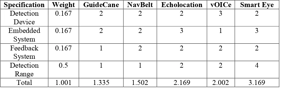
Table 2.3 Weighted Objective Table for aid devices
Specification Weight GuideCane NavBelt Echolocation vOICe Smart Eye Detection
Device 0.167 2 2 2 3 2
Embedded
System 0.167 2 2 3 1 3
Feedback
System 0.167 1 2 2 2 2
Detection
Range 0.5 1 1 2 2 4
Total 1.001 1.335 1.502 2.169 2.002 3.169
2.2.5 Summary of Literature Review
9 user. Two sonar sensors used in this system will not enough. This is because 2 quantities of sensors can only detect the obstacle in front of the user and cannot detect the obstacle beside of the user. The vOICe project is using image to sound concept. This project is using digital camera that attached to eye glass, a headphone for feedback and portable computer for software communicate. This project is not good enough because it need to bring along a portable computer during using it. It is heavy and not comfort when a user need brings a portable computer to walk around. So, this project is design out with 4 sonar sensor place on a spectacle for head-level obstacle detection control by microcontroller and sound system for alert system. In the weighted objective table, the Smart Eye gets 3.169 point, the highest point among the entire devices. This means that Smart Eye is better than other devices.
2.7 Sensor Comparison
In this section, the features of 3 different distance sensors will be list out and features comparison between these 3 sensors will be done.
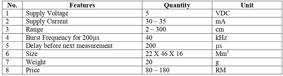
2.7.1 PING)))™ Ultrasonic Distance Sensor (#28015) [10]
10
Figure 2.5 Ultrasonic Distance Sensor
Table 2.4 Features for Ultrasonic Distance Sensor
No. Features Quantity Unit
1 Supply Voltage 5 VDC
2 Supply Current 30 – 35 mA
3 Range 2 – 300 cm
4 Burst Frequency for 200µs 40 kHz
5 Delay before next measurement 200 µs
6 Size 22 X 46 X 16 Mm3
7 Weight 20 g
8 Price 80 – 180 RM
Theory of Operation
11
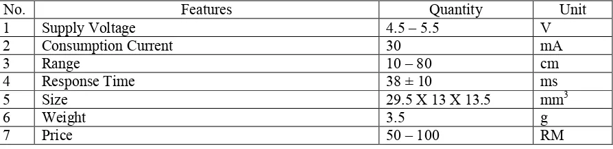
2.7.2 Infrared Distance Sensor (GP2Y0A21YK0F) [9]
GP2Y0A21YK0F is an infrared distance measuring sensor unit (Figure 2.6) which integrated with combination of PSD (position sensitive detector), IRED (infrared emitting diode) and signal processing circuit. The variety of the reflectivity of the object, the environmental temperature and the operating duration are not influenced to the distance detection because of adopting the triangulation method. This device output the voltage corresponding to the detection distance. So this sensor can be used as a proximity sensor. The features of Infrared Distance Sensor are show in table form (Table 2.5).
Figure 2.6 Distance Sensor (GP2Y0A21YK0F)
Table 2.5 Features for Infrared Distance Sensor
No. Features Quantity Unit
1 Supply Voltage 4.5 – 5.5 V
2 Consumption Current 30 mA
3 Range 10 – 80 cm
4 Response Time 38 ± 10 ms
5 Size 29.5 X 13 X 13.5 mm3
6 Weight 3.5 g
12 Theory of Operation
A pulse of IR light is emitted by infrared emitting diode. This light will travels out in the field of view and either hits an object or just keep on going. In case there is no object, the light will never reflect. If the light reflects off an object, it returns to the position sensitive detector and creates a triangle between the point of reflection, the emitter, and the detector. The conductivity of position sensitive detector is depending on the position where the beam falls. The conductivity is converted to voltage and the distance can be calculated.
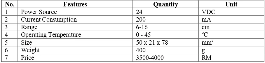
2.7.3 Laser Distance Sensor (MX1C)
MX1C is a type of laser distance sensor (Figure 2.7). Its detection range is 6cm to 160cm. The sensor is easy to align with its red laser.
Figure 2.7 Laser Sensor (URG-04LX-UG01)
Table 2.6 Feature for Laser Sensor
No. Features Quantity Unit
1 Power Source 24 VDC
2 Current Consumption 200 mA
3 Range 6-16 cm
4 Operating Temperature 0 - 45 oC
5 Size 50 x 21 x 78 mm3
6 Weight 400 g
![Figure 2.2 How the GuideCane avoids obstacles. [3]](https://thumb-ap.123doks.com/thumbv2/123dok/575579.68245/17.595.234.380.118.329/figure-guidecane-avoids-obstacles.webp)
![Figure 2.4 vOICe prototype. [7]](https://thumb-ap.123doks.com/thumbv2/123dok/575579.68245/19.595.78.534.634.767/figure-voice-prototype.webp)