i
I/We admit that have read this report and in my/our opinion, this report is enough in terms of scope and quality to bestowal Bachelor of Mechanical Engineering
(Automotive)
Signature : ……….
Supervisor I : Mr. Faizul Akmar Bin Abdul Kadir
Date : ……….
Signature : ………. Supervisor II : ……….
ii
COMPARISON BETWEEN COMBINATION SILENCER AND SINGLE TYPE SILENCER FOR TWO-STROKE NOISE REDUCTION AND ITS EFFECT ON
ENGINE POWER CURVE.
MOHD ARIFF BIN ARSHAD B040610129
This report is submitted in partial fulfillment of the requirement for the Bachelor of Mechanical Engineering (Automotive)
Faculty of Mechanical Engineering Universiti Teknikal Malaysia Melaka (UteM)
iii
I declare that this report is my own work except for any summary or quotation from every single source is explained.
iv
v
ACKNOWLEDGMENT
Alhamdulillah thanks to Allah for the all the Rahmah that He have given to us, for me to finally finish this project for Projek Sarjana Muda 2. I also like to say my thanks to En. Faizul Akmar for his guidance and help to complete this report in time.
I also like to thank the university staff such the technicians especially En. Nasir, En Syakir and Cik Hidayah in guiding and helping me to understand better about the motorcycle and the engine and using the equipments to complete my tasks. All of their help and guidance are really appreciated.
Here I also like to say thank you to En. Suzairin from UTHM for giving us the permission to use their equipment to complete this project. His help is really appreciated.
vi
ABSTRACT
vii
ABSTRAK
viii
TABLE OF CONTENTS
CHAPTER SUBJECT PAGES
DECLARATION iii
DEDICATION iv
ACKNOWLEDGEMENT v
ABSTRACT vi
ABSTRAK vii
CONTENTS viii
LIST OF FIGURES xii
LIST OF TABLES xv
LIST OF SYMBOLS xvi
CHAPTER 1 INTRODUCTION 1
1.1Project background 1
1.2Importance of the Project 2
1.3 Objective 2
1.4Scope 3
ix
CHAPTER 2 LITERATURE REVIEW 4
2.1 Types of Silencer 4
2.1.1 Diffusion Silencer 4
2.1.2 Absorption Silencer 5
2.1.3 Combination Silencer 6
2.2 Silencer’s Volume 7
2.3 Exhaust System 7
2.4 Noise Control 8
2.4.1 Characteristics of Sound and
How It Was Produce 9
2.4.2 Noise 11
2.4.3 Vehicle Noise 12
2.4.4 Effects of Sound Pollutions
to the Environment 13
2.5 Two-stroke Internal Combustion Engine 15
2.5.1 The Concept of Two-stroke Engine 16
2.5.2 Combustion of Two-stroke Engine 17
2.5.3 The Difference of Two-Stroke Engines
And a Four-Stroke Engines. 19
2.5.4 The Source of Noise in Two-Stroke
x
2.6 Dynamometer 20
CHAPTER 3 METHODOLOGY 23
3.1 Gathering Information and Reference 25
3.1.1 Literature Review. 25
3.1.2 Study on an Available Product 25 3.2 Source of Problem 26 3.3 Solving Problems. 26
3.4 Design of Silencer. 27
3.5 Gathering Data and Analysis 27
3.6 Discussions 29
CHAPTER 4 DESIGN AND FABRICATION 30
4.1Parameter Assessments. 30
4.2Materials Used 34
4.3 Fabrication of the Silencers. 34
4.4 Method of Testing 36
CHAPTER 5 RESULTS 39
5.1Results for Noise Reduction. 39 5.1.1 Noise Value without Silencers. 40 5.1.2 Noise After Silencer Is Installed. 41
5.1.2.1Results for Single Type
Silencer 42
xi
Type Silencers 43
5.2Results for Rig Testing. 45
5.2.1 Results for Single Type Silencers 45 5.2.2 Results for Combination Type Silencers 46
CHAPTER 6 DISCUSSIONS 49
6.1 Silencers Effects to the Sound Produce 49 6.2 Silencers Effects on the Brake Power. 52 CHAPTER 7 CONCLUSIONS AND RECOMMENDATIONS 53
7.1 Conclusion 53
7.2 Recommendations. 54
REFERENCE 55
BIBLIOGRAPHY 56
xii
LIST OF FIGURES
NO. TITLE PAGES
2.1 Sound wave reflection inside the silencers
chamber. 5
2.2 Transmission loss graph of silencer with and
without absorption material. 6 2.3 Backpressures which occur in a two-stroke
engine. 8
2.4 Comparison of sounds and their average sound
pressure level (SPL) - shown in decibels. 12
2.5 An outline of a two-stroke engine. 16
2.6 Process in a two-stroke engine. 18
2.7 A simple electrical dynamometer setup showing
engine, torque measurement arrangement and
tachometer. 22
xiii
4.1 Parameters that is being studied. 31
4.2 Silencer fixed parameter. 32
4.3 The fiberglass composite inside the silencer. 36
4.4 The silencer being welded. 36
4.5 A digital sound level meter. 36
4.6 Setting-up the motorcycle on the dynamometer. 37
4.7 Holding position of sound level meter. 38
5.1 Specification of parameters for combination type silencer. 40
5.2 Graph Engine Speed vs Noise without silencers 41
5.3 Graph engine speed vs noise for Design 1. 42
5.4 Graph engine speed vs noise for Design 2. 42
5.5 Graph engine speed vs noise for Design 3 43
5.6 Graph engine speed vs noise for Design 4 43
5.7 Graph engine speed vs noise for Design 5 44
5.8 Graph engine speed vs noise for Design 6 44
5.9 Graph engine speed vs brake power for Design 1 45
5.10 Graph engine speed vs brake power for Design 2 46
5.11 Graph engine speed vs brake power for Design 3 46
5.12 Graph engine speed vs brake power for Design 4 47
5.13 Graph engine speed vs brake power for Design 5 47
xiv
xv
LIST OF TABLES
BIL. TITLE PAGE
2.1 The differences between two-stroke and
four-stroke engine. 19
xvi
LIST OF SYMBOLS
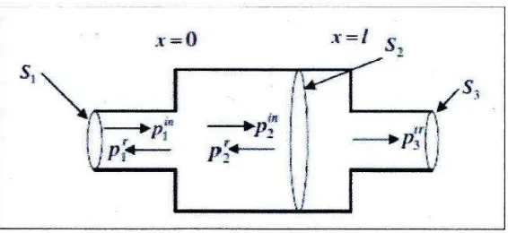
pin = Sound wave from the source.
Pr = Sound wave that was deflected.
Ptr = Sound wave produced.
S = Cross sectional area. Nh = Number of holes.
Ah = Area of a hole.
A3 = Sectional area of the pipe.
X = Ratio number.
L = Sound level (dB)
P = Sound pressure at the measured place. (u bar).
Po = Pressure of air (2 × 10 ‾4 u bar). PKw = Power in kilowatts.
τN·m = Torque in Newton meters.
ωrpm = Rotational velocity in revolutions per minute. L =Length of the silencer,
xvii
l1in = Length of inlet inner pipe, l2out = Length of outlet outer pipe,
1
CHAPTER I
INTRODUCTION
1.1 Project background.
This project is done to compare between a single type silencer of diffusion, absorption and a combinational type silencer diffusion and absorption. To do this, the silencer is fabricated and mounted to a two-stroke internal combustion engine where the effect of the sound produced from the silencer is experimented. Other than that, the effect on engine power also will be experimented.
2
The focus of this project is to run an experiment by making single type silencer (diffusion and absorption) and several combination type silencers (diffusion
+ absorption). Every silencer will be mounted to an 110cc motorcycle engine where the noise of each of them will be taken before and after various installations. Then, a dynamometer test will be done to see the effect of the silencer on the engine power. The best silencer will be chose after all the analysis is done.
1.2 Importance of the project.
3
1.3 Objective.
The objective of this project is to study the effect of a single type and combinational type of silencer (diffusion and absorption) towards noise reduction of the two-stroke internal combustion engine and its effect on engine power curve experimentally.
1.4Scope.
There are several scopes that need to be followed:
Finding a suitable two-stroke engine.
Produce silencers (based on suggestions from PSM 2 2008/2009).
Study the engine noise before and after various silencer installations (experimental).
To produce rig for dynamometer testing.
To study the effect of silencer on engine power (experimental).
1.5Problem statement.
4
5
CHAPTER II
LITERATURE REVIEW
2.1 Types of Silencer
Silencer or also known as muffler is device that reduces amount of noise that is produce by a machine, in this case an engine. There are many types of silencer in the market, but there are three basic types of silencer, diffusion, absorption and resonance. For this project, we will only focus on experimenting diffusion, absorption, and combination of these silencers.
2.1.1 Diffusion Silencer.
6
closed cylindrical chamber before entering to another small pipe at the end of it. Here is where the sound will be deflected by the sound wave from the engine simultaneously due to the different of cross section area that the sound wave has to go through.
[image:23.595.180.463.292.422.2]The standard design for a diffusion silencer basically has an inlet pipe, a closed cylindrical chamber and an outlet pipe. This type of silencer is widely used for all internal combustion engines especially cars and motorcycles. It’s effectively muffled sound at low frequency which is suitable for a high performance engine and can withstand a low reversal pressure.
Figure 2.1: Sound wave reflection inside the silencers chamber (Josh Seslar, 2005).
2.1.2 Absorption Silencer.
7
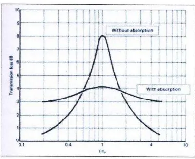
[image:24.595.218.418.171.334.2]change into heat. With this we can eliminate the wideband noise at the medium and high frequency.
Figure 2.2: Transmission loss graph of silencer with and without absorption material (Taylor & Francis, 1991).
The silencer consists of absorption material which is place in a closed cylindrical chamber with a hollow pipe in the middle. Selection of materials as a absorption device also play an important to make sure it can work properly. Usually it has a certain lifespan. Therefore the material needs to be replaced at a certain amount of time when it reaches its lifetime. If not, the silencer will not work accordingly or failed to work.