FORCE TRACKING CONTROL OF MAGNETO-RHEOLOGICAL (MR) DAMPER USING PI CONTROL
MOHD ZUBIR BIN AMIR
This report is written as a partial fulfillment of terms in achieving the awards for
Bachelor of Mechanical Engineering (Automotive)
Faculty of Mechanical Engineering
Universiti Teknikal Malaysia Melaka
CONFESSION
“I admit that this report is from my own work and idea except for the summary and a few sections which were extracted from other resources as being mention”.
Signature :………...
Writer Name :………...
FOR MY LOVELY PARENTS, MY BROTHERS AND MY SISTERS, GIVE ME A SPIRIT AND INDUCEMENT TO SUCCESS IN MY STUDIES AND MY FUTURE. TO ALL MY LECTURER AND FRIENDS, SPECIAL THANKS FROM
ACKNOWLEDGEMENT
Firstly I want to give high appreciation to my supervisor, Dr Khisbullah Huda cause guidance and inducement me to finish my PSM (Projek Sarjana Muda). En Ubaidillah as a master student also guidance me gave many information to help me do my project.
All of cooperation from order master student, Fitrian, Zulkifli, Fauzi and Alif when do my experiment also very appreciated to them.
ABSTRAK
ABSTRACT
TABLE OF CONTENT
CHAPTER TITLE PAGE
CONFESSION i
DEDICATION ii
ACKNOWLEDGEMENT iii
ABSTRAK iv
ABSTRACT v
CONTENTS vi
TABLE viii
FIGURE xi
CHAPTER 1 INTRODUCTION 1
1.1 Background 1
1.2 Problem Statement 2 1.3 Objective 2 1.4 Scope 3
1.5 Outline 3 CHAPTER 2 LITERATURE REVIEW 5
2.1 Introduction of Automotive Suspension 5 System 2.2 Magneto-Rheological (MR) Damper 6
2.3 Magneto-rheological (MR) Fluid 7 2.3.1 Mathematical model 8
2.4 Existing Model 12 2.5 PI Control 13 2.6 Force Tracking Control 15 CHAPTER 3 METHODOLOGY 18
3.1 Flowchart and Explanation 19
3.1.1 Flowchart 19
3.1.2 Explanation 21
3.2 Experiment and Procedure 22
3.2.1.1 Existing model of 22 MR damper
3.2.1.2 Suspension test machine 23
3.2.2 Instrumentation 24
3.3 Instrument Setting 28
3.4 Technical Specification 29
3.4.1 Linear Variable Displacement 29
Transducer (LVDT)
3.4.2 Load cell 30
3.4.3 IMC Device 31
3.5 Result Variable 32
CHAPTER 4 RESULT AND DISCUSSION 36
4.1 Simulation Study of 6th Order 36
Polynomial
4.2 Inverse Model 40
4.3 Experimental Result 41
4.4 Model Validation 43
4.5 Force Tracking Control of The 46
Proposed MR Damper Model
4.6 Discussion 54
CHAPTER 5 CONCLUSION AND RECOMMENDATION 55
5.1 Conclusion 55
5.2 Recommendation 56
REFERENCE 57
BIBLIOGRAPHY 59
LIST OF TABLE
NO TITLE PAGE
4.1 Coefficients of the 6th order polynomial 39
LIST OF FIGURE
NO TITLE PAGE
2.1 Schematic diagram of suspension system 6
2.2 No magnetic field 7
2.3 With magnetic field 7
2.4 Bingham model of a MR damper 8
2.5 Comparison between the Predicted and 10
Experimentally
Obtained Responses for the Bingham Model
2.6 Bouc-Wen Model of the MR Damper 11
2.7 Using MR damper model from Delphi 12
2.8 Schematic of MR Damper Design 12
2.9 Feedback system 13
3.1 Flowchart 19
3.2 MR Damper from Delphi 22
3.3 Quarter car model rig test 23
3.4 Shaft between motor and damper 23
3.5 Motor 24
3.6 Bridge Amplifier 24
3.7 Load cell 25
3.8 LVDT 25
3.9 Computer 26
3.10 Variable AC motor drive 26
3.11 DAQ module 27
3.12 Laboratory DC power supply 27
3.13 Schematic diagram for Force Tracking Control 28
3.15 Load cell 30
3.16 Schematic diagram of Load cell 30
3.17 IMC device 31
3.18 Input kgraw(loadcell) output is Nraw filter by 33 filteringraw
3.19 Input lvdtraw output is lvdtraw1 filter by 33 filteringrawvel
3.20 Tuning the graph into zero by filteringrawveltuned 34
3.21 Tuning the graph to center the graph by 34 filteringrawtuned and filteringrawtunedforce
3.22 Graph of Force vs Displacement 35
3.23 Graph of Force vs Velocity 35
4.1 The structure of the 6th order polynomial model 37
4.2 Hard points taken from the experimental result 37
4.3 The linear regression of the coefficients ai correspond 39
to the input current for upper curves
4.4 The linear regression of the coefficients ai correspond 40
to the input current for lower curves
4.5 Measured forces for six constant current levels 42
4.6 Force-velocity characteristic for five constant current 42
levels
4.7 Force-displacement characteristic for five constant 43
current levels
4.8 Comparison of the measured and predicted damping 44
forces for:0.5Amp. (a), 1Amp. (b),Applied currents
4.9 Comparison of the measured and predicted damping 44
forces for: 1.5Amp. (c)and 2Amp. (d) Applied currents
4.10 Damping force characteristics under various input 45 currents 0.35Amp
4.11 Damping force characteristics under various input 45 currents 0.75Amp.
4.13 Force-displacement characteristics comparison of 46 polynomial model and experimental result
4.14 The structure of force tracking control of MR damper 47
4.15 The experimental results of force tracking control under 48 several sinusoidal amplitudes of the desired forces at the
frequency of 0.7Hz: (a) 500N
4.16 The experimental results of force tracking control under 48 several sinusoidal amplitudes of the desired forces at the
frequency of 0.7Hz: (b) 800N
4.17 The experimental results of force tracking control under 49 several sinusoidal amplitudes of the desired forces at the
frequency of 0.7Hz: (c) 1100N
4.18 The experimental results of force tracking control under 49 several sinusoidal amplitudes of the desired forces at the
frequency of 0.7Hz: (d) 1300N
4.19 The experimental results of force tracking control under 50 several sinusoidal amplitudes of the desired forces at the
frequency of 1.08Hz: (a) 500N
4.20 The experimental results of force tracking control under 50 several sinusoidal amplitudes of the desired forces at the
frequency of 1.08Hz: (b) 800N
4.21 The experimental results of force tracking control under 51 several sinusoidal amplitudes of the desired forces at the
frequency of 1.08Hz: (c) 1100N
4.22 The experimental results of force tracking control under 51 several sinusoidal amplitudes of the desired forces at the
frequency of 1.08Hz: (d) 1300N
4.23 The experimental results of force tracking control under 52 several sinusoidal amplitudes of the desired forces at the
frequency of 1.5Hz: (a) 500N
frequency of 1.5Hz: (b) 800N
4.25 The experimental results of force tracking control under 53 several sinusoidal amplitudes of the desired forces at the
frequency of 1.5Hz: (c) 1100N
4.26 The experimental results of force tracking control under 53 several sinusoidal amplitudes of the desired forces at the
CHAPTER 1
INTRODUCTION
1.1 Background
The purpose of this project is to see the performance of Magneto-rheological (MR) damper using PI control. A few years ago, automotive suspension designs have been a compromise between the two conflicting criteria of road holding and passenger comfort. The suspension system must support the weight of the vehicle, provide directional control during handling maneuvers, and provide effective isolation of passengers and payload from road disturbances.Suspension is the term given to the system of springs, shock absorbers and linkages that connects a vehicle to its wheels. Suspension systems serve a dual purpose contributing to the cars handling and braking for good active safety and driving pleasure, and keeping vehicle occupants comfortable and reasonably well isolated from road noise, bumps, and vibrations.
vehicle suspensions like passive, semi-active and active suspensions, which depend on the operation mode to improve vehicle ride. Inside damper it has solenoid and MR fluid to control the hydraulic damper. When current is supply, the particles of MR Fluid forms in direction chains. In this condition, the damper is controlled by MR damper.
1.2 Problem Statement
Magneto-rheological (MR) damper is semi-active devices are controlling by current. MR fluid inside MR damper change from liquid into semi solid when current is applies. MR damper can generate force from viscous or viscoelastic plastic fluid. MR dampers contain controllable fluids that can change their properties when exposed to magnetic fields. By controlling the current to an electromagnetic coil inside the piston of the damper, the MR fluid’s viscosity can be changed, resulting in continuously variable real-time damping system. MR damper is a relatively a recent damping device, in which the magnitude of the resisting force acting upon a mechanical structure can be adjusted in real time. Adjustment takes place by varying the amount of current passing through wires embedded in the damper. Use the suitable method to track the desired damping force.
1.3 Objective
To study the simulation of Magneto rheological (MR) Damper force tracking
control using 6th polynomial model.
Experimental work of Magneto rheological (MR) Damper force tracking
control.
1.4 Scope
Experimental of MR damper use Delphi A33 manufactured by Delphi Automotive System. Simulink of Magneto-rheological (MR) Damper use Matlab Simulink. Validation and evaluation between the desire force and actual force for the Magneto-rheological (MR) Damper by experimentally use quarter car test rig.
1.5 Outline
CHAPTER 1
For this chapter is an introduction about this project. Inside chapter 1, it has background, problem statement, objective and scope.
CHAPTER 2
Chapter 2 is a literature review. This chapter include introduction of automotive suspension system, Magneto-rheological (MR) damper, Magneto-rheological (MR) Fluid, Mathematical model, Existing model, PI control, and Force tracking control.
CHAPTER 3
Chapter 3 is about methodology. This chapter content, Flowchart, Explanation, Experiment setup and procedure, Equipment, Instrumentation, Instrument setting, Technical specification, and Result variable.
CHAPTER 4
CHAPTER 5
CHAPTER 2
LITERATURE REVIEW
2.1 Introduction of Automotive Suspension System
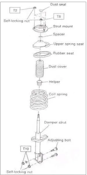
The suspension system isolates the body from road shocks and vibrations which would otherwise be transferred to the passengers and load. It also must keep the tires in contact with the road. When a tire hits an obstruction, there is a reaction force. The size of this reaction force depends on the unsprung mass at each wheel assembly. The sprung mass is that part of the vehicle supported by the springs and unsprung mass not supported by the springs. Vehicle ride and handling can be improved by keeping unsprung mass as low as possible. Basic suspension systems are included like springs, axles, shock absorbers, arms, rods, and ball joints. Modern passenger vehicles usually use light coil springs. Light commercial vehicles have heavier springs than passenger vehicles, and can have coil springs at the front and leaf springs at the rear. Heavy commercial vehicles usually use leaf springs, or air suspension.
Figure 2.1: Schematic diagram of suspension system
2.2 Magneto-Rheological (MR) Damper
2.3 Magneto-rheological (MR) Fluid
[image:20.612.265.405.270.349.2]Magneto-Rheological (MR) fluids respond to a magnetic field with a dramatic change in rheological behavior. These fluids can reversibly and instantaneously change from a free-flowing liquid to a semi-solid with controllable yield strength when exposed to a magnetic field.The magnetic particles, which are typically micrometer or nanometer scale spheres or ellipsoids, are suspended within the carrier oil are distributed randomly and in suspension under normal circumstances, as shown in Figure 2.2.
Figure 2.2: No magnetic field
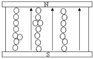
When a magnetic field is applied, however, the microscopic particles align themselves along the lines of magnetic flux, as shown in Figure 2.3. When the fluid is contained between two poles, the resulting chains of particles restrict the movement of the fluid, perpendicular to the direction of flux, effectively increasing its viscosity. Importantly, mechanical properties of the fluid in its on state are anisotropic. Thus in designing a magneto-rheological device, it is crucial to ensure that the lines of flux are perpendicular to the direction of the motion to be restricted.
[image:20.612.258.421.562.666.2]2.3.1 Mathematical model
The stress-strain behavior of the Bingham viscoplastic model can be used to describe the behavior of MR fluids. In this model, the plastic viscosity is defined as the slope of the measured shear stress versus shear strain rate data. That is
where is the yield stress induced by the magnetic field and µ is the viscosity
[image:21.612.245.437.299.377.2]of the fluid.
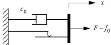
Figure 2.4: Bingham model of a MR damper
(Source: Spencer, Dyke, Sain & Carlson March 10, 1996)
Based on the Bingham model of the MR fluids, a modified model is proposed to describe the behavior of the MR damper. The model consists of a Coulomb friction element placed in parallel with a viscous damper, as shown in Figure 2.4. In this model, the force generated by the device is given by
where c is the damping coefficient and f is related to the fluid yield stress and the
input voltage. F0 is used to reflect the offset effect due to the accumulator in the MR
The force f is expressed as
eq. (4)
where f
0 is the friction force, v is the input voltage to the MR damper and G is the gain of the induced force. After insert eq. (4) into eq. (3), the mathematical model of the MR damper is given by
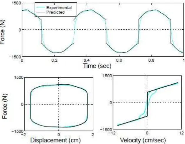
Figure 2.5: Comparison between the Predicted and Experimentally
Obtained Responses for the Bingham Model (Source: Spencer, Dyke, Sain & Carlson March 10, 1996)
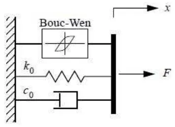
Figure 2.6: Bouc-Wen Model of the MR Damper
(Source: Spencer, Dyke, Sain & Carlson March 10, 1996)
The parameters of the model and A will be adjusted so that one can
control the linearity in the unloading and the smoothness of the transition from the
pre-yield to the post-yield region. The force due to the accumulator can be directly
incorporated into this model as an initial deflection of the linear spring . To
obtain the governing equations for this model, consider only the upper section of the model. The forces on either side of the rigid bar are equivalent. Therefore,
Where the evolutionary variable is governed by