INITIAL OBSERVATION OF ENERGY CONVERSION BY USING RECTENNA
NUR IZNI BINTI ROSLAN
This Report Is Submitted in Partial Fulfillment of Requirements for the Bachelor Degree of Electronic Engineering (Wireless Communication)
Faculty of Electronic and Computer Engineering Universiti Teknikal Malaysia Melaka
UNIVERSITI TEKNIKAL MALAYSIA MELAKA
FAKULTI KEJURUTERAAN ELEKTRONIK DAN KEJURUTERAAN KOMPUTER
BORANG PENGESAHAN STATUS LAPORAN PROJEK SARJANA MUDA II
Tajuk Projek : INITIAL OBSERVATION OF ENERGY CONVERSION BY USING RECTENNA Sesi
Pengajian : 1 2 / 1 3
Saya NUR IZNI BINTI ROSLAN
mengaku membenarkan Laporan Projek Sarjana Muda ini disimpan di Perpustakaan dengan syarat-syarat kegunaan seperti berikut:
1. Laporan adalah hakmilik Universiti Teknikal Malaysia Melaka.
2. Perpustakaan dibenarkan membuat salinan untuk tujuan pengajian sahaja.
3. Perpustakaan dibenarkan membuat salinan laporan ini sebagai bahan pertukaran antara
institusi pengajian tinggi.
4. Sila tandakan ( √ ) :
SULIT*
*(Mengandungi maklumat yang berdarjah keselamatan atau kepentingan Malaysia seperti yang termaktub di dalam AKTA RAHSIA RASMI 1972)
TERHAD** **(Mengandungi maklumat terhad yang telah ditentukan oleh
organisasi/badan di mana penyelidikan dijalankan)
TIDAK TERHAD
Disahkan oleh:
__________________________ ___________________________________
(TANDATANGAN PENULIS) (COP DAN TANDATANGAN PENYELIA)
iii
“I hereby declare that this report is the result of my own work except for quotes as cited
in the reference”
Signature : ………
Author : NUR IZNI BINTI ROSLAN
iv
“I hereby declare that I have read this report and in my opinion this report is sufficient in
terms of the scope and quality for the award of Bachelor of Electronic
Engineering (Wireless Communication) With Honours”
Signature : ………..
Supervisor’s Name : ENGR. NAJMIAH RADIAH BINTI MOHAMAD
v
Special dedicate to my family, supervisor, and all my fellow friends to help me to
vi
ACKNOWLEDGEMENT
In the name of Allah, The Most Gracious, The Most Merciful. Firstly, an utmost
gratitude to Allah S.W.T for giving me comforts patience and opportunity in time and
space to successfully complete my final year project thesis or Project Sarjana Muda
(PSM) 2.
Millions of thanks also are giving to my supervisor, Engr. Najmiah Radiah Binti
Mohamad for the guidance and advice, including the feedback that enabled me to
improve upon producing this report.
I wish to express my appreciation to my friends, Nur Hidayah Binti Mahmud for
sharing the literature and similar research interest and also for her help and
encouragement in designing rectenna. I also like to express my gratitude to all those who
have helped me in one way or another way during the planning, information gathering,
writing, editing and reformatting stages of this thesis report.
Besides that, I would like to express my gratitude to my parents for the love and
support that they have given me. Finally, I would like to thank everyone who is willing
vii
ABSTRACT
Nowadays, the battery is one of a necessary device for everyone in their life.
Battery always been the problem which is the lifetime of the battery is very limited and
requiring periodical battery replacement. The deposition of battery is creating the
problem of environmental pollution. So, this project was designed rectenna to capture
and converts the microwave energy to DC voltage that can supply energy for
low-voltage devices without using electricity or battery automatically. The law of
conservation energy stated that the energy cannot be created and destroyed. Energy
conversion is the process of converting one form of energy into another form.This thesis
describes the original work on converting microwave energy to DC voltage by using
rectenna. Rectenna is a combination of a rectifying circuit and an antenna. The antenna
part will capture electromagnetic energy from free space and convert it into an electrical
signal. It was designed by using CST microwave studio software and fabricated on FR4
board because the printed rectenna is easy to manufacture. The frequency selected for
the antenna is 2.45 GHz, which means the antenna should be able to operate in that
frequency because the probability to get high efficiency rectenna is high and it
unlicensed frequency band. Rectenna will convert the microwave energy into DC power
by using rectifier circuit. Rectifier circuit is consisting of Schottky diode and resistor for
power measurement. Based on the experimental results, the highest output voltage
measure is 1.695V at 820kΩ and 20dBm input power. This project is successfully
proven that rectenna can power up low-voltage device such as LED, which is can
viii
ABSTRAK
Kini, bateri merupakan salah satu alat yang diperlukan oleh setiap orang dalam
kehidupan mereka. Bateri sentiasa menjadi masalah di mana jangka hayat bateri adalah
sangat terhad dan memerlukan penggantian bateri secara berkala. Pemendapan bateri
mewujudkan masalah pencemaran alam sekitar. Oleh itu, projek ini telah mereka
rectenna untuk menangkap dan menukarkan tenaga gelombang mikro kepada voltan DC
dan dijangka dapat memberi fungsi kepada peralatan voltan rendah tanpa menggunakan
elektrik atau bateri secara automatik. Prinsip keabadian tenaga menyatakan bahawa
tenaga tidak boleh dicipta dan dimusnahkan. Penukaran tenaga adalah proses
menukarkan satu bentuk tenaga ke bentuk yang lain. Tesis ini menerangkan kerja-kerja
asal untuk menukar gelombang mikro ke voltan DC dengan menggunakan rectenna.
Rectenna merupakan gabungan litar penerus dan antena. Bahagian antena akan
menangkap tenaga elektromagnetik dari ruang bebas dan menukarkannya menjadi
isyarat elektrik. Ia direka bentuk dengan menggunakan perisian CST studio microwave
dan difabrikasi di atas papan FR4 kerana rectenna cetakan lebih mudah untuk direka.
Kekerapan yang dipilih untuk antena adalah 2.45GHz, iaitu bermaksud antena dapat
beroperasi pada frekuensi tersebut kerana kebarangkalian untuk memperoleh kecekapan
antena yang tinggi adalah besar. dan ia merupakan jalur frekuensi yang tidak berlesen.
Rectenna akan menukar tenaga gelombang mikro ke kuasa DC menggunakan litar
penerus. Litar penerus terdiri daripada diod schottky dan perintang untuk pengukuran
kuasa. Berdasarkan keputusan eksperimen, nilai voltan keluaran paling tinggi adalah
1.695V pada 820kΩ dan 20dBm kuasa masukan. Projek ini telah berjaya membuktikan
bahawa rectenna mampu memberi kuasa kepada peralatan bervoltan rendah seperti LED,
ix
TABLE OF CONTENT
CHAPTER CONTENT PAGE
PROJECT TITLE i
REPORT STATUS VERIFICATION ii
STUDENT’S DECLARATION iii
SUPERVISIOR DECLARATION iv
DEDICATION v
ACKNOWLEDGEMENT vi
ABSTRACT vii
ABSTRAK viii
CONTENT ix
LIST OF TABLES xiii
LIST OF FIGURES xiv
LIST OF ABBREVIATION xvi
I INTRODUCTION 1
1.1 Project Overview 1
1.2 Objectives 2
1.3 Problem Statement 2
1.4 Project Scope 3
1.5 Methodology 4
x
II LITERATURE REVIEW 7
2.1 Wireless Energy Harvesting 7
2.2 Microwave Energy 8
2.3 Operation of Rectenna 9
2.3.1 Antenna 11
2.3.2 Rectifying Circuit 11
2.3.3 Filter 12
2.4 Rectenna Applications 13
III THEORETICAL BACKGROUND 15
3.1 Microstrip Patch Antenna 15
3.2 Microstrip Patch Calculation 17
3.3 Antenna Polarization 19
3.3.1 Linear Polarization 20
3.3.2 Circular Polarization 20
3.3.3 Elliptical Polarization 21
3.4 Advantages and Disadvantages of Patch Antenna 21
IV METHODOLOGY 22
4.1 Software for Simulation 22
4.2 Materials 23
4.2.1 FR4 Board 23
4.2.2 Schottky Diode 24
xi
4.3 Equipments 25
4.3.1 RF Signal Generator 26
4.3.2 RF Cable 26
4.3.3 Horn Antenna 27
4.3.4 Digital Multimeter 27
4.4 Dimension of Proposed Antenna 28
4.5 Dimension of Proposed Rectifier 28
4.6 Project Procedure 29
4.6.1 Antenna Design Procedure 29
4.6.2 Rectifier Design Procedure 32
4.6.3 Etching Process Procedure 34
4.6.4 Rectenna Measurement Using Horn Antenna 36
4.6.5 Measurement Procedure 37
4.6.6 Rectenna Test Using Wireless Router 39
4.7 Overall Budgets 40
V RESULT AND DISCUSSION 41
5.1 Simulation Result 41
xii
5.3 Measurement Result 49
5.3.1 Output voltage versus power transmit
at distance 20 cm 49
5.3.2 Output voltage versus power transmit
at distance 40 cm 51
5.3.3 Output voltage versus power transmit
at distance 60 cm 51
5.4 Testing Result 54
5.5 Analysis of Rectenna Design 54
VI CONCLUSION AND RECOMMENDATION 56
6.1 Conclusion 56
6.2 Recommendation for Future Project 56
REFERENCES 58
xiii
LIST OF TABLES
No Title Page
4.1 FR4 board specification 24
4.2 Overall budgets for the project 40
xiv
LIST OF FIGURES
No Title Page
1.1 Block diagram rectenna system 3
1.2 Flow chart for the rectenna project 5
2.1 Schematic diagram of microwave 9
2.2 Schematic rectenna system 11
2.3 Electric circuit for the Schottky diode 12
3.1 Illustration of microstrip patch antenna 17
3.2 Antenna polarization 19
3.3 Circular Polarization 20
4.1 CST microwave studio software 23
4.2 Example of FR4 board 24
4.3 HSMS 2860 surface mount microwave schottky diode 25
4.4 Resistor 25
4.5 RF Signal generator 26
4.6 RF cable 26
4.7 Horn antenna 27
4.8 Digital multimeter 28
4.9 Drawing of FR4 substrate in CST 30
4.10 Drawing of patch antenna on FR4 substrate in CST 30
4.11 Drawing of ground at an opposite side on FR4 substrate in CST 31
xv
4.13 Antenna dimensions 32
4.14 Rectenna with the dimension 33
4.15 Rectifier dimensions with diode and resistor connection 33
4.16 Rectenna layouts for etching process 34
4.17 Chemical for etching process (ferric chloride) 34
4.18 Etching process 35
4.19 Printed rectenna on FR4 board 35
4.20 Rectenna measurement setup 36
4.21 Rectenna arrangement 37
4.22 Output voltages when RF signal generator is “OFF” 38
4.23 Output voltages when RF signal generator is “ON” 38
4.24 D-Link wireless router 39
4.25 Light-Emitting Diode (LED) 40
5.1 S-parameter magnitude in dB 43
5.2 Surface current on antenna patch 44
5.3 S-parameter for Smith Chart 45
5.4 3D view of radiation pattern gain 46
5.5 Polar view of radiation pattern gain 46
5.6 3D view of radiation pattern directivity 47
5.7 Polar view of radiation pattern directivity 48
5.8 Output voltage versus power transmit at distance 20cm 50
5.9 Output voltage versus power transmit at distance 40cm 51
5.10 Output voltage versus power transmit at distance 60cm 52
5.11 Output voltage versus power transmit at different distance 53
xvi
LIST OF ABBREVIATIONS
RF - Radio Frequency
AC - Alternating Current
DC - Direct Current
FR4 - Flame Retardant 4
RECTENNA - Rectifying Antenna
FET - Field Effect Transistor
HEMT - High Electron Mobility Transistor
LED - Light-Emitting Diode
CST - Computer Simulation Technology
ISM - Industrial, Scientific and Medical
EM - Electromagnetic
LPF - Low Pass Filter
EDA - Electronic Design Automation
PCB - Printed Circuit Board
RHC - Right Handed Circular
LHC - Left Handed Circular
1
CHAPTER I
INTRODUCTION
This chapter will include the overview of the project that consists of project background, project objective, project scope, project methodology, and summarization of the project.
1.1 Project Overview
2
Effect Transistor (FET) or High Electron Mobility Transistor (HEMT) appear in recent years (the rectenna using the active devices is not passive element).
G. A. Vera had developed rectennas which approximately 90% the RF-DC conversion efficiency at 8 Watt input of 2.45 GHz microwave and it was the world record. The RF-DC conversion efficiency of the rectenna with a diode depends upon the microwave power input intensity and the optimum connected load. When the power overload is not matched the efficiency becomes quite low. The characteristic is determined by the characteristic of the diode. The diode has its own junction voltage and breakdown voltage, if the input voltage across the diode is lower than the junction voltage or is higher than the breakdown voltage; the diode does not show a rectifying characteristic. As a result, the RF-DC conversion efficiency drops with a lower or higher input than the optimum [1].
1.2 Objectives
The objective of this project is to design and fabricate the rectenna which captures and converts the microwave energy to DC voltage. Due to the green technology that's highly demands these days, the project seems to be useful to a future because it uses microwave energy to generate new power, and it also can be used as the alternative power source in the future. Another objective of this paper is to observe and analyze the rectenna characteristics such as power efficiency. This project is expected can help to supply energy for low-voltage devices such as Light-Emitting Diode (LED) without the need any electricity or battery as the source.
1.3 Problem Statement
3
become part of human life. Battery always been the problem which is the lifetime of the battery is very limited even for low-power battery, requiring impractical periodical battery replacement. In addition, the deposition of battery is creating the problem of environmental pollution.
The research regarding rectenna was being done a long time ago, but there is also a problem reported regarding rectenna design and performance that need to fix. For example, Yu-Jiun Ren and Kai Chang reported that the dual diode rectenna only could provide 76% of conversion efficiency [2]. Besides that, J. A. G Akkermans and et al. reported in their journal that the amounts of power that can be transferred by using rectenna are limited due to free space path loss [3]. From another journal, Hu Hao and Kong Li also reported that, higher rectenna frequency (e.g. 35 GHz) could reduce the aperture area and increase the transmission range but the component to generating that frequencies are expensive and inefficient [4].
From our own finding after doing a measurement from designing an antenna are we found that the ambient frequency is not having sufficient power to produce high-output DC voltage. The transmit power will be sufficient when generate it using the RF signal generator.
As a conclusion, this project is undertaken as a solution for problems reported in a related journal about designing good rectenna and to get the better output.
1.4 Project Scope
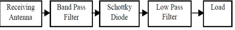
[image:19.595.130.513.693.743.2]The scope for this project is to find a solution to convert the energy from the microwave to DC power and to increase the efficiency of power conversion. Rectenna will be used to capture the microwave signal and convert it to DC power.
4
Receiving antenna converts the input microwave signal into voltages and currents. The rectifying circuit consists of a band-pass filter, a Schottky diode, and a low-pass filter. The diode is the main part of the rectifying circuit; it changes the AC microwave signal into a DC signal. The properties of the diode significantly impact the overall performance; a diode with a lower built-in voltage would realize a higher rectifying efficiency. Because of its nonlinear characteristics, the diode will create harmonic signals, which can in turn be radiated by the antenna into the ambient space and absorbed by the material of the rectenna. This harmonic generation process can notably decrease the rectifying efficiency to the system.
Consequently, a band-pass filter is usually incorporated within the system between the antenna and the diode to block any harmonics generated by the diode, as well as the diode-generated DC current, from flowing into the antenna. Analogously, a low-pass filter is typically introduced after the diode to prevent any AC signals from reaching the load. Rectenna was designed by using Computer Simulation Technology (CST) Microwave Studio software and fabricated on Flame Retardant 4 (FR4) board because the printed rectenna is low-cost and easy to manufacture. We have investigated the output rectifying efficiency with a resistor load. The resistor senses and, hence, measures the output power directly. However, this project is simply focused onto the output and the capability of rectenna to convert a microwave signal into DC power only.
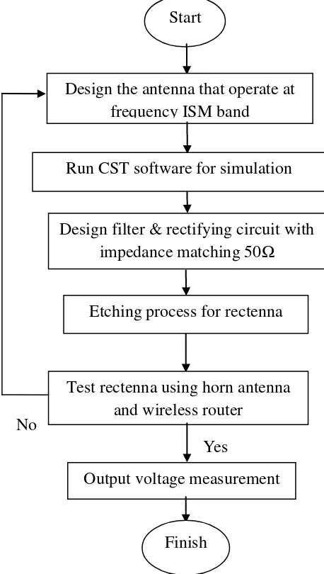
1.5 Methodology
5
Since the stub (filter) part, it is designed to pass the frequency of ISM band, which is 2.4 GHz to 2.45 GHz. The filter should be able to block higher-order harmonic frequency and must match with antenna and rectifying circuit. For the rectifying circuit, there are two types of diode configuration, the first is a single diode configuration which provides half-wave rectifier and the second is dual diode configuration, which provides full-wave rectifier. For this project, dual diode configuration was selected.
[image:21.595.206.435.329.734.2]Rectenna is tested using the horn antenna because a horn antenna is one of the good antennas for testing method. The characteristics of the horn antenna are having the high gain and directivity. It is also used during the transmission and reception of microwave signals. Finally, the output voltage of the rectenna is observing.
Figure 1.2 : Flow chart for the rectenna project Start
Design the antenna that operate at frequency ISM band
Run CST software for simulation
Test rectenna using horn antenna and wireless router
Output voltage measurement Design filter & rectifying circuit with
impedance matching 50Ω
No
Etching process for rectenna
6
1.6 Thesis Outline
This report contains six chapters that will explain details on the project of designing rectenna which converting from RF energy to DC voltage.
The first chapter in this report is an introduction. This chapter will include the overview of the project which is project background, project objective, project scope, project methodology, and summarization of the project.
The second chapter is a literature review. This chapter will discuss about the fact and information from various sources before proceeds with the project. This part also discussed about the current study of rectenna findings.
The third chapter is a theoretical background for a project. This chapter will discuss about the fact, and obtains information from various sources required to precede the project. The component and any other material will be discussed within this chapter.
The fourth chapter is a methodology where it will describe the methods and techniques that have been used for this project. This chapter will give detailed information on the materials, equipment, and experimental procedures that will be used for this project.
The fifth chapter is about result and discussion. This section will explain as the result from the project, the analysis of results. The method used to analyze results will be explains.
7
CHAPTER II
LITERATURE REVIEW
This chapter will discuss about the fact and information about the finding and research from various sources before proceeding with the project. This part also discussed about the current study of rectenna findings.
2.1 Wireless Energy Harvesting
Wireless energy harvesting is any of several methods of converting the signal to DC voltage without the use of cables or device-specific AC adaptors. It can be to power up or charging for a wide variety of devices, including cell phones, laptop computers and MPEG3 (MP3) players as well as larger objects, such as robots and electric cars.
8
harvesting has become an appealing solution to prolong the lifetime of wireless networks. Unlike battery-powered networks, energy harvesting wireless networks potentially have an unlimited energy supply from the environment. Consequently, the research on wireless networks powered by renewable energy has recently drawn a great deal of attention [5].
L. Liu and et al. stated that an ambient radio signals can be a viable new source for wireless energy harvesting to other commonly used energy sources such as solar and wind. Since radio signals carry information as well as energy at the same time, an interesting new research direction, namely “simultaneous wireless
information and power transfer”, have recently been pursued [6].
2.2 Microwave Energy
Microwave energy is electromagnetic waves used for wireless communication such as radio, television, and radar. There are three different microwave frequencies available for industrial application. The microwaves travel with the speed of light. Microwaves are electromagnetic waves with wavelengths longer than those of terahertz (THz) frequencies, but relatively short for radio waves. Microwaves have wavelengths approximately in the range of 30 cm at 1 mm. The term microwave generally refers to alternating current signals with frequencies between 300 MHz and 300 GHz.
Figure 2.1 shows the schematic diagram of microwave propagation, where E,
H, λ, and c are electric field, magnetic field, wavelength, and speed of light,