i
AUTOMATIC ACCIDENT DETECTOR AND NOTIFICATION
NORFAUZAN BIN RAHMAN
This Report Is Submitted In Partial Fulfillment of Requirements For The Bachelor Degree of Electronic Engineering (Wireless Communication)
Fakulti Kejuruteraan Elektronik dan Kejuruteraan Komputer Universiti Teknikal Malaysia Melaka
ii
iii
“I acknowledge that this report is entirely my work except summary and passage I have quoted the source”
Signature :-………..
Author Name :- NORFAUZAN BIN RAHMAN
iv
‘I acknowledge that I have read this thesis and in my opinion this thesis is sufficient in terms of scope and quality for the award of Bachelor of Electronic Engineering
(Telecommunication Electronics)”
Signature :-……….
Supervisor Name : - EN. MOHD SA’ARI BIN MOHAMMAD ISA
v
vi
ACKNOWLEDGEMENT
First of all, I am grateful to Allah for blessing me good health in completing this
project. I would like to dedicate my gratitude towards my parents for their love and supports. Without their support, I do not think that I can stand here completing this project.
I also want to say thanks to my supervisor En. Mohd Sa’ari Bin Mohammad Isa for his guidance and help during the period of this project and also to all lecture for giving me knowledge while I am studying in UTeM
vii
ABSTRACT
viii
ABSTRAK
x
TABLE OF CONTENT
CHAPTER TITLE PAGES
PROJECT TITLE i
PSM STATUS VERIATION FORM ii
DECLARATION iii
SUPERVISOR VERICATION FORM iv
DEDICATION v
ACKNOWLEDGEMENT vi
ABSTRACT vii
ABSTRAK viii
TABLE OF CONTENT x
LIST OF TABLE xiv
LIST OF FIGURE xv
LIST OF APPENDICES xviii
I INTRODUCTION
1.0 Introduction 1
1.2 Objectives Project 3
1.3 Problem Statement 3
1.4 Scope of project 4
xi
II LITERATURE REVIEW
2.0 Chapter Overview 7
2.1 Previous Project 8
2.1.1 Automated Profile Vehicle 8 Using GSM Modem, GPS
and Media Processor DM642
2.1.2 Automatic Vehicle Accident 9 Detection and Messaging System
Using GSM and GPS Modems
2.1.3 Wireless Accident Information 10 System Using GSM and GPS
2.2 GPS Technology 10
2.3 GSM Technology and Architecture for 13 GSM Network
2.4 Microcontroller 15
2.5 Universal Asynchronous Receiver and 16 Transmitter (UART)
2.6 RS 232 Serial communication 16
2.7 CCS Complier 18
2.8 Proteus Design Suite 7.8 19
2.9 Microsoft Visual Studio 2010 20 2.10 The Advantages and Benefit of This Project 21
III METHODOLOGY
3.0 Introduction 22
3.1 Project planning 23
3.2 Phase one 24
xii 3.4 Software development process 27 3.5 Hardware development process 29
IV BACKGROUND
4.0 Introduction 31
4.1 NEO-6M GPS Receiver 32
4.2 GSM Modem 33
4.3 PIC 16F877a 35
4.4 MAX232 37
4.5 LM 7805 Voltage regulator 38
4.6 Crystal Oscillator 39
V RESULT AND DISCUSSION
5.0 Introduction 41
5.1 Software Implementation on microcontroller 42 5.1.1 Sending SMS coding development 42 5.1.2 Reading GPS NMEA data coding 46
development
5.1.3 Combining source code and set the 49 Accident condition
5.2 Interface in VB.net 51
5.3 Hardware development 54
xiii
VI CONCLUSION AND SUGGESTION
5.1 Conclusion 62
5.2 Suggestion 63
5.2.1 Auto-Dial system 64
5.2.2 Security Technology 64
xiv
LIST OF TABLES
TABLE NO. TITLE PAGE
2.1 Voltage level for RS232 16
2.2 DB-9 pin description 18
4.1 Specification for NEO-6M 33
4.2 Table of logic level for RS232 and TTL 38
5.1 AT command 43
xv
LIST OF FIGURE
FIGURE NO. TITLE PAGE
1.1 Scope of work diagram 5
2.1 3GPP Family Technology Evolution 13
2.2 GSM Network overview 14
2.3 UART packet format 15
2.4 DB-9 pinsouts 17
3.1 Flow chart project 23
3.2 Analysis project flow 25
3.3 Block diagram overall project 26
3.4 Software development process 28
3.5 Hardware development process 29
4.1 GPS Receiver 32
xvi 4.3 PIC 16F877a and schematics diagram 35
4.4 16f877a pin digram 36
4.5 MAX 232 37
4.6 Schematics diagram for voltage regulator 38
4.7 Crystal Oscillator 39
5.1 Complete AT command in sending SMS 43
5.2 Result in sending SMS 44
5.3 Basic sending 45
5.4 Simulation sending SMS 46
5.5 Result in reading GPS data 47
5.6 Transmit source code 48
5.7 Simulation result in reading GPS data 48
5.8 PIC Burner 50
5.9 GSM Modem connection to PC 51
5.10 Parameter setting for Modem 52
5.11 VB to Google maps URL 53
5.12 AADN GUI 54
5.13 Pick device interface 55
5.14 AADN schematic circuit 56
5.15 PCB layout for AADN 57
xvii 5.17 Back, front and top side switch position 59
5.18 SMS contents 60
xviii
APPENDICES
NO. TITLE PAGE
A SOURCE CODE SENDING 67
1
Chapter 1
INTRODUCTION
1.0 Introduction
The statistic of transport ministry of Malaysia [1], the rapid growth and increase traffic on the highway accident rate increased every year especially during the festival seasons. From [2] after the feast show that 19 person died each day and from the 5 years record show 17 died per day regardless of whether weekdays or weekends. It shows that thousands of road users in Malaysia died each year and more victims suffered severe and permanent injuries due to the emergency help failed to respond in time.
2
victims. The possibility of saving lives increase when crash victims receive medical attention within the first hour [3]. Most accidental deaths occur within a few hours of the automotive accident. 30% of death occurs within minutes of the crash [3].
Since the early information is the essential tools about of saving process, the effort to develop can be done to alert the service providers to take faster action toward an accident. In this project automatic accident detector and notification is a project to inform the owner or related trough SMS to a mobile phone. A technology to automatically detect the vehicle crash and then provides dispatcher with information about the crash event for the information about the level the accident will be developed the precious accident time, location and severance will be collected and conveyed to the central for relay such information to the rescue parties involved.
For nowadays technologies, some of company in Malaysia has developing GPS system which can protect their consumers from vehicle thief. The Captor-GPS is one of the products made from Netstar Advanced System (M) Sdn. Bhd that provide the consumers latest GPS tracking system for locating consumer vehicle when there are theft activities occurred. If violation is detected, SMS alerts will be sent to up to 2
mobiles. The Owner will confirm theft activities and notifies CAPTOR’s 24 hour Call
Center. The CAPTOR Recovery Teams dispatched to recover stolen vehicle. [4]
3
provider in the form SMS then will be transmitted to the service provider whose will take the necessary action according to accident indicator.
The process that required to be success and to be implemented in this project is how to design, develop and deploy an accident and notification to service provider. This project also needs to understand about software been involved in this project such as PIC C Compiler and Visual Basic. The needed to learn and practicing technical skills to overcome problems occurred in implementing the project are been addicted. This project also needs to analyze the system performance for project goal achievement confirmation by comparing it to the theoretical or expected results (analytical skill).
1.2 Objective Project
The main objective of this project is to design, develop and deploy an accident detector and notification system. To design it need to understand the microcontroller characteristics of this system and know to develop the software that being running on this project which is PIC C compiler (CCS) and Visual basic. Moreover it must be learn and practice technical skills to overcome problem occur in implement the project.
1.3 Problem Statement
4
phone number to service provider such as 999 rescue squad, ambulance and any related of it.
While developing this project, a few problems were encountered. One of it is no auto-dial system to react fast system if the crash is a critical accident. This situation needs to be noticed because the system will interface on accident and the severity of accident must equally concern to protect the system from critical damage.
One of the problem is the system cannot use at the place with no network coverage. Since the communication by using an SMS, The best telecommunication provider need to be choose to get the better coverage for the system.
1.4 Work
5
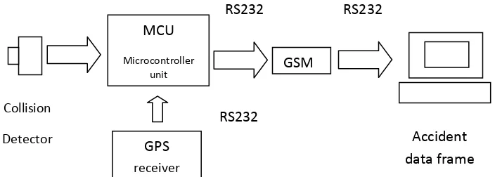
Figure 1.1: Scope of work diagram
Block description:
1. Collision detector : To detect the level of collision and send to MCU
2. GPS Receiver: Detect the time, date, longitude and latitude of the accident location. The Recommended Minimum Specific (RMC) NMEA protocol for U-Blox 6 GPS module been selected.
3. Microcontroller Unit (MCU):
Processing unit that received input signal from sensor and GPS Receiver then it will continually storing in the buffer (RAM or data storage) and process it to get the output desired. The output will be sending the result via using GSM modem. 4. GSM: GSM modem is a device that sending and receives the information by
SMS. The AT commands are required to sending and receive the SMS.
5. RS232: Is an asynchronous serial communication method which is sending the information one bit at a time. GSM modem and GPS receiver are required RS232.
6. PC: will receive the information from the MCU via SMS. The GSM modem will receive the SMS and send the information by RS232. Visual Basic. Net will be an interface for service provider to collect the information about the accident.
6
1.5 Software Simulation
There are four different types of software used in this project. HyperTerminal software is software that can be used to send and receive the SMS. The AT command set is used for this purpose. The second one is for microcontroller programming. CCS Complier software is used to write the code for microcontroller programming. The programming of the microcontroller is done in C language. The AT command set also include in this software for sending data about the severity of collision together with the location and time by SMS.