UNIVERSITI TEKNIKAL MALAYSIA MELAKA
STRATEGY FOR MILLING THIN-WALL LOW
RIGIDITY CURVE SHAPE COMPONENT
2012
MUHAMMAD HELMIE BIN ASNAN
UNIVERSITI TEKNIKAL MALAYSIA MELAKA
This report submitted in accordance with requirement of the Universiti Teknikal Malaysia Melaka (UTeM) for the Bachelor Degree of Manufacturing Engineering
(Process) with Hons.
by
MUHAMMAD HELMIE BIN ASNAN B050910258
880122086315
FACULTY OF MANUFACTURING ENGINEERING 2012
UNIVERSITI TEKNIKAL MALAYSIA
MELAKA
BORANG PENGESAHAN STATUS LAPORAN PROJEK SARJANA MUDA
TAJUK: Strategy for Milling Thin-Wall Low Rigidity Curve Shape Component
SESI PENGAJIAN: 2011/12 Semester 1
Saya MUHAMMAD HELMIE BIN ASNAN (B050910258)
mengaku membenarkan Laporan PSM ini disimpan di Perpustakaan Universiti Teknikal Malaysia Melaka (UTeM) dengan syarat-syarat kegunaan seperti berikut:
1. Laporan PSM adalah hak milik Universiti Teknikal Malaysia Melaka dan penulis.
2. Perpustakaan Universiti Teknikal Malaysia Melaka dibenarkan membuat salinan untuk tujuan pengajian sahaja dengan izin penulis.
3. Perpustakaan dibenarkan membuat salinan laporan PSM ini sebagai bahan pertukaran antara institusi pengajian tinggi.
4. **Sila tandakan (√)
SULIT
TERHAD
TIDAK TERHAD
(Mengandungi maklumat yang berdarjah keselamatan atau kepentingan Malaysia yang termaktub di dalam AKTA RAHSIA RASMI 1972)
(Mengandungi maklumat TERHAD yang telah ditentukan oleh organisasi/badan di mana penyelidikan dijalankan)
Alamat Tetap:
I hereby, declared this report entitled “Strategy for Milling Thin-Wall Low Rigidity Curve Shape Component” is the results of my own research except as cited in
references.
Signature :
Author’s Name : MUHAMMAD HELMIE BIN ASNAN
Date :
APPROVAL
This report is submitted to the Faculty of Manufacturing Engineering of UTeM as a partial fulfillment of the requirements for the degree of Bachelor of Manufacturing Engineering (Process) (Hons.). The member of the supervisory is as follow:
i Pada masa sekarang, terdapat pelbagai situasi dimana mata alat dari jenis lansing digunakan bagi tujuan pemotongan benda kerja dinding nipis yang berbentuk lengkung. Kegunaan ini biasanya terdapat pada teknologi pemesinan bahagian pada badan pesawat/kapal terbang. Dalam kes ini, banyak kecacatan telah berlaku iaitu pemesongan pada badan kerja. Projek ini menjalankan kajian tentang cara yang betul dan effektif dengan mengubah kedudukan dan pergerakan mata alat untuk mendapatkan produk yang dimensinya tepat. Untuk kajian ini, cara ‘compensation’ digunakan. Cara ini berdasarkan pada perubahan pada pergerakan mata pemotong pada magnitude permukaan yang salah yang telah diperolehi dari pemesinan awal. Ketepatan dan efektif proses ini dinilai berdasarkan kekasaran permukaan dan ketepatan dimensi produk.
ii There are many machining situations where slender tools are used to machine thin walled curve shape workpiece. Such instances are more common in machining of aircraft structural parts. In these cases, the workpiece deflections are quite common which result into surface error on machined components. This project presents a methodology for tool path compensation for effectively machining curve shape thin walled geometries by modifying the tool paths. The cutter compensation method is based on the adjustment of cutter path with respect to the magnitude of surface errors obtained from the preliminary machining with ideal cutter path. The effectiveness of the compensation strategy is then evaluated by measuring the component accuracy and surface roughness.
iii
To my beloved parents.
iv Alhamdulillah, Thanks to the entire Almighty from Allah for giving me all the strength and good health to complete this report without problems and barriers. This report is finally completed with much assistance of many people.
I would like to express the deepest appreciation to Universiti Teknikal Melaysia Melaka for providing such a brilliant facility such as equipment and machine for me to fulfil PSM requirement that’s need to use while the project is carry on .
Besides that, I am heartily thankful to my supervisor, En. Raja Izamshah Bin Raja Abdullah, whose encouragement, guidance and support from the initial to the final level enabled me to develop an understanding of the research. I am truly grateful for his the time spent proofreading and correcting my many mistakes, his tolerance of my mistakes, and his commitment to my future career.
In addition, I would like to thank all manufacturing engineering department lab staff for giving me an opportunity to work in a good and productive environment. Their continuous support and guidance whenever problems occurred while I was performing new task is really an encouragement in making me to perform at my very best. This has partly contributed to the success of my research and the completion of this ‘Projek Sarjana Muda’.
Last but not least I would like to thank my friends especially those who help to contribute the idea and solution while the research is carry on. Thank you.
v
List Abbreviations, Symbols and Nomenclature xii
CHAPTER 1 : INTRODUCTION 1
1.1 Research Background 1
1.2 Problem Statement 2
1.3 Objective 3
1.4 Project Scope 4
CHAPTER 2: LITERATURE RIVIEWS 5
2.1 Related Works 6
2.2 Overview Compensation Method 9
2.3 Overview of 4 To 1 Rule Strategy 11
2.4 Workpiece Properties 12
2.4.1 Aluminium 13
2.4.2 Phase Diagram 15
CHAPTER 3: METHODOLOGY 16
3.1 Level 1: Method and Approach Use 18
3.1.1 8 to 1 Rule 18
3.1.2 Compensation Method 19
3.1.3 Non-Compensation Method 20
3.1.4 Machining Parameter 21
vi
3.2 Level 2: Product Part 18
3.2.1 Sample Product Part 22
3.2.2 Research Product Part 25
3.2.3 Clamping Position 25
3.3 Level 3: Software Selection 27
3.3.1 CATIA v5r19 27
3.3.1.1 Draw The actual Product Process 28
3.3.1.2 Machining Simulation 32
3.3.1.3 Code Generate 37
3.3.2 SolidWorks 2010 39
3.4 Level 4: Part Fabrication and Machining Process 40
3.4.1 CNC Machine 40
3.5 Level 5: Testing and Evaluation 41
3.5.1 Surface Roughness, Ra 41
3.5.1.1 Surface Tester Machine 41
3.5.1.2 Surface Tester Machine Calibration. 42
3.5.2 Dimension Accuracy 43
3.5.2.1 Coordinate Measuring Machine 43
3.5.2.2 CMM calibration 45
3.5.4 Dynometer 46
3.5 Level 6: Result Analysis 47
3.6 Level 7: Conclusion 47
CHAPTER 4: RESULT AND ANALYSIS 49
4.1 4 to 1 Result 49
4.2 Non Compensation Result 52
4.3 Compensation Result 59
4.4 Cutting Force Result 68
4.5.1 Non-Compensation Force Result 4.5.2 Compensation Force Result
vii
CHAPTER 5 CONCLUSION 75
5.1 Conclusion 75
Reference 77
Appendix
A PSM 1 Gantt Chart B PSM 2 Gantt Chart C 2mm Thin-Wall Drawing D 6mm Thin-Wall Drawing
viii
2.1 Aluminium Properties 14
3.1 Cutting Parameter for Experiment 21
4.1 6mm Thickness of Thin wall Result 51
4.2 Error of 6mm Thickness Result 51
4.3 Final Thickness of 2mm Thin-Wall Using Non-Compensation Method
54
4.4 Error for 5mm Thin-Wall Thickness 55
4.5 Error for 4mm Thin-Wall Thickness 56
4.6 Error for 3mm Thin-Wall Thickness 57
4.7 Error for 2mm Thin-Wall Thickness 58
4.8 Final Thickness of 2mm Thin-Wall Using Compensation Method 60
4.9 Error for 5mm Thin-Wall Thickness 61
4.10 Error for 4mm Thin-Wall Thickness 62
4.11 Error for 3mm Thin-Wall Thickness 64
4.12 Error for 2mm Thin-Wall Thickness 66
4.13 Non-compensation Surface Result 74
4.14 Compensation Surface Result 74
ix 1.1 Isometric Views Of Thin-Wall Cutting Process 2
1.2 Deflection On The Thin Wall 3
2.1a Effects Of Machining Surface On Cutter Path (Without Cutter Compensation)
9
2.1b Effects Of Machining Surface On Cutter Path (With Cutter Compensation)
9
2.2 Compensation Equation 10
2.3 Cutter Compensation Method. 10
2.4 The Application Of The 8:1 Rule 11
2.5 Aluminium Phase Diagram 15
3.1 Thin-Wall Component 17
3.2 Process Plan Flowchart 17
3.3 4 To 1 Rule (24 Mm Depth Of Cut) 18
3.4 Cutting Tool Position in Compensation Method 19 3.5 Cutting Tool Position in Non-Compensated Method 20
3.6 Product Part Flowchart 22
3.7 Stock size 23
3.8 The Stock After Roughing Process 23
3.9 Final sample product 24
3.10 Final Product Part 25
3.11 Hole For Screw Clamping On Working Table 26
3.12 Flowchart to Obtain NC Code 27
3.13 Mechanical Design Mode 28
3.14 Sketching 29
3.15 Pad Definition 29
3.16 Thin-Wall Sketching 30
3.17 Thin-Wall Pad Definition 30
x
3.18 Stock 31
3.19 Actual Product 31
3.20 Part Operation Setting 32
3.21 Datum Reference Setting 32
3.22 Machine Type Selection (Milling 5-axis) 33
3.23 Multi-Flank Countering Feature 33
3.24 Profile and Face Selection 34
3.25 Guidance and Tool axis Setting 34
3.26 Macro Management 35
3.27 Tooling Setting 35
3.28 Video Simulation Using Tool path Toolbar 36
3.29 Simulation 36
3.30 Generate NC code Interactively Toolbar 37
3.31 Generate NC code Interactively Setting 37
3.32 Generate NC code Interactively Setting 2 38
3.33 CNC milling 5-axis HAAS 40
3.34 Portable Surface Roughness Tester Mitutoyo SJ-301/0.75mn (178-955-2E)
42
3.35 SurfTest calibrate surface 42
3.36 Coordinate Measuring Machine, WENZEL 3D/ LH 5.6.4 43
3.37 Measuring points. 44
3.38 Mitutoyo gauge block series sets 45
3.39 Dynometer 46
4.1 Aluminium Bar 48
4.2 6mm size of thin-wall thickness 50
4.3 Final Thickness 2mm using Non-Compensation Method 52 4.4 Graph of thin-wall variation for 5mm (non-compensated) 55
4.5 New coordinate for 6 to 5mm 55
4.6 Graph of thin-wall variation for 4mm (non-compensated) 56
4.7 New coordinate for 5mm to 4mm 56
4.8 Graph of thin-wall variation for 3mm (non-compensated) 57
xi 4.10 Graph of thin-wall variation for 2mm (non-compensated) 58
4.11 New coordinate for 3mm to 2mm 58
4.12 Graph of thin-wall variation for 5mm (Compensated) 61 4.13 Graph of thin-wall variation for 4mm (Compensated) 63 4.14 Graph of thin-wall variation for 3mm (Compensated) 65 4.15 Graph of thin-wall variation for 2mm (Compensated) 67
4.16 Force generate to x-axis for 4mm to 3mm 68
4.17 Force generate to y-axis for 4mm to 3mm 69
4.18 Force generate to x-axis for 3mm to 2mm 69
4.19 Force generate to y-axis for 3mm to 2mm 70
4.20 Force generate to x-axis for 4mm to 3mm 71
4.21 Force generate to y-axis for 4mm to 3mm 71
4.22 Force generate to x-axis for 3mm to 2mm 72
4.23 Force generate to y-axis for 3mm to 2mm 72
xii
% - Percent
2D - 2 Dimension
3D - 3 Dimension
Al - Aluminium
ANN - Artificial Neural Network CAM - Computer Aided Manufacturing
Catia - Computer Aided Three-Dimensional Interactive CMM - Coordinate Measuring Machine
CNC - Computer Numerical Control
Cº - Degree Celsius
FEA - Finite Element Analysis
Gpa - Giga Pascal
PNN - Polynomial Neural Network
Ra - Arithmetic Average of Absolute Value
RPM - Revolution Per Minute
Ti - Titanium
This chapter reviews and describe the detail about the objective of the research for milling thin-wall low rigidity curve shape component. The objective clearly instructs what the researcher should do and what specific measure that must be follows in order to achieve the goal. The scope prevents the researcher from do the unneeded task that has no connection with the research topic.
1.1 Research Background
Milling of complex thin walled geometries is becoming increasingly important in aerospace industries due to its ability to produce complex parts as monolithic structures. The need for expensive multi-part manufacturing, large set up times on different machines and assembling of pieces together into finished product is eliminated here because the complete part is manufactured from a single piece by material removal processes. Many of the thin walled components produced in these industries are curve shape in nature. Closed nature of curve shape structures provides much needed stiffness to the components in resisting machining induced forces. In spite of this, a major problem associated with milling of thin walled curve shape components is cutting force induced static deflections of cutter and workpiece which manifest in form of surface error on finished parts. Highly non-linear and complex nature of surface error profiles during milling of such components not only deteriorates its dimensional accuracy but also geometric tolerances.
INTRODUCTION
1.2 Problem Statement
It is challenging task for the process planner to obtain tight dimensional and geometric tolerances dictated by functional requirements of the product. One of the approaches is to use conservative cutting conditions and multi-pass machining to limit cutting forces. Such an approach reduces surface error but hampers productivity of machining operation significantly. Yet another approach is to use final “float” cut to bring machined surface within required tolerance. It is not advisable to take “float” cut in thin-walled machining as it may not be effective due to compliant nature of the workpiece. In such machining situations, single pass off-line tool path modification strategy can be considered as one of the efficient ways to produce thin walled quality parts without sacrificing productivity.
This report presents a methodology to predict and compensate surface errors in milling of thin walled curve shape structures. The effectiveness of the compensation strategy is evaluated by measuring the component accuracy and the surface roughness.
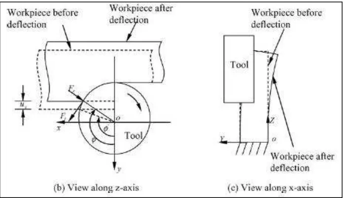
Figure 1.2: Deflection on the thin wall. (Ratchev, 2004)
1.3 Objective
The objective of this study as follow:
i. to develop a tool path compensation strategy for milling thin-wall low rigidity curve shape component
1.4 Project Scope
Literature reviews, Chapter 3, are reviewing the relevant literatures about the method or approach that use to machining monolithic part which is aerospace part. This chapter also covered machining parameter that need to consider and the detail about the material type use to produce the part.
Section 2.1 Reviews the detail about the related works that has been done to produce the part base on the approach or the technique to fabricate the monolithic part. The related works are reviews such as, surface finish Ra, machining time and accuracy of
dimensional that produce by the selected method.
Section 2.2 Reviews the detail compensation method and working principle
Section 2.3 Reviews the detail 8 to 1 rule Method and the working principle for workpiece preparation.
Section 2.4 Reviews on the aluminium material properties that related to the machining process. Reference from CES EduPack version 6.2.0 software and related journal about aluminium material is use for this section.
LITERATURE REVIEW
1.5 Related Works
Number of research attempts can be found in literature that deals with reduction of cutting force induced tool or workpiece deflection errors. But very few of these attempts are focused on reduction of combined tool and workpiece deflection errors. Research attempts focusing on reduction of deflection induced surface error can be broadly categorized into three groups:
i. Process design approach which controls cutting forces during machining by varying cutting parameters such as feed rate (Tarng and Cheng, 1993; Budak and Altintas, 1994) or cutting widths (Ryu and Chu, 2005) so that deflections do not exceed beyond specified limits,
ii. On line adaptive control approach proposes shifting of cutting tool in real time (Yang and Choi, 1998) necessitating use of measurement sensors and hardware,
iii. Off-line tool path modification approach consisting of correcting tool path on the basis of known surface error before performing actual milling operation.
(OMM) system was emphasized for improvement in measurement accuracy and reduction of setup time (Cho et al., 2003).
It has been highlighted by many researchers that the predicted surface error can also be used to obtain compensated tool path so that an additional experimentation can be avoided. Based on this fact, an off-line tool path compensation methodology was proposed by Suh et al. (1996) for reduction of surface error during two-dimensional contour machining. The developed methodology computes modified tool path on the basis of tool deflection error predicted using process simulation models. Landon et al. (2003) applied compensation methodology for correction of tool path deformed due to action of cutting force on cutting tool, tool holder and spindle assembly. Depince and Hascoet (2006) carried out detailed investigations on surface error profile generated due to tool deflections and proposed a technique to obtain optimized tool path trajectory that achieves specified tolerances on finished components.