1. INTRODUCTION
PRECISION positioning systems are fundamental components and becoming significantly important to many industrial applications such as machine tools, measuring machines and semiconductor manufacturing systems. The demands of high precision performance have drastically increased in recent years. The ever-increasing demands on higher and better performances of the machines have motivated and stimulated the development of high quality positioning systems. Positioning systems strictly require the kind of controller which is easy to design and has simple structure, fast response, no or small overshoot, high robustness performance and high accuracy and/or resolution where is better than 10nm [1].
In spite of the advances in mathematical control theory over the last few decades, industrial servo controllers are still essentially based on the three-term PID controller. The main reason is due to the need of a practical and simple controller in industrial applications and it has been effective and reliable in most situations if adequately tuned. However, PID controller has met the limitation when a higher positioning performance and robust system are required. In achieving the better requirements, different types of controller have been proposed, such as disturbance observer [2-5], time-optimal controllers [6-7] and sliding mode controllers [8-9]. These advanced controllers require the determination of exact model of the plant while it spends much time and labour to identify its parameters. It is difficult for engineers or operators who are unfamiliar with advanced control to adjust and handle the control parameters in industrial. Besides, those more complex advanced intelligent control methods, such as fuzzy logic and neural network controllers have fared
less favorably under practical conditions. For overcoming these occurred problems, NCTF (Nominal Characteristic Trajectory Following) controller has been proposed as a practical controller, especially in industry. NCTF controller is able to satisfy the above mentioned positioning system requirements where it does not require an exact model and given parameters of the object, which the object characteristic is already identified and included in open-loop time responses. Besides, NCTF controller has simple structure which is easy to design and adjusted, even in non-linear mechanism. It shows the higher robustness performance than PID controller.
Previous works of NCTF controller have been proposed and accomplished for positioning control in mechanism with friction [1][10-14]. Many results were evaluated and it showed the applicability and successfulness of the controller in positioning control with mechanisms with friction. For non-friction and non-damping mechanisms, the design procedure of NCTF controller is not yet proposed and achieved in positioning control. Since the non-contact mechanism has non-damping characteristic and often has short working range, a suitable current input which able to stop the non-damping mechanism within short working range in open-loop condition is needed. Besides, a suitable current input is important to produce a suitable NCT which will easier the mechanism to follow NCT and produce a smoothness motion trajectory.
The remainder of this paper is organized as follows: Section 2 describes the modeling of mechanism and experimental setup. Section 3 presents the proposed NCTF control concept and its design procedures. Section 4 presents experimental results. Concluding remarks are given in Section 5.
Practical Control of Non-Friction Mechanism for Precision Positioning
Shin-Horng CHONG and Kaiji SATO
1
Interdisciplinary Graduate School of Science and Engineering, Tokyo Institute of Technology 4259 Nagatsuta, Midori-ku, Yokohama 226-8502, Japan
(Tel : +81-45-924-5045); E-mail: [email protected]
2. EXPERIMENTAL SETUP
For the experimental setup, the air-slide mechanism as shown in Fig. 1 is driven by voice-coil motor (VCM). The mechanism is expressed as one mass mechanism which could move in one direction only. As additional information of interest, the PWM amplifier (Bipolar Power Supply, BPS 40-15) is limited at 45V/A. The controller sampling frequency is 5kHz and its feedback position is determined by a laser position sensor with resolution of 1.24nm (Agilent: 10897B).
In the present experimental setup, the system is considered as non-friction mechanism because of the location of air-bearing. The air-bearing has the air supply from air compressor. It was placed at the position where will produce the lowest affect to the mechanism.
The mechanism could be considered as a simple model which has a single mass with few model parameters only. However, in many controller designs, time is spent to identify the force constant which is determined by using load-cell. The governing equations of the 1DOF mechanism system are the equation of motion on the table and the equation of the VCM. Equation of motion:
f
m=
M
x
(
t
)
(1) Equation of the VCM:f
m=
K
fu
r (2) From these governing equations, the open-loop transfer function of the mechanism as follow2 2
)
(
)
(
)
(
s
K
Ms
K
s
U
s
X
s
G
p=
=
f=
fm (3)where
K
fm=
K
fM
Table 1 Parameters of the developed 1DOF mechanism
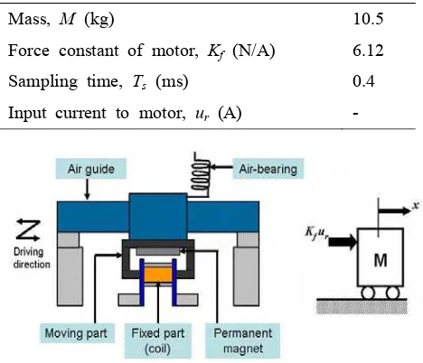
Mass, M (kg) 10.5
Force constant of motor, Kf (N/A) 6.12
Sampling time, Ts (ms) 0.4
Input current to motor, ur (A) -
Fig. 1 1-DOF air-slide mechanism and dynamic model.
3. NCTF CONTROL SYSTEM
3.1 NCTF Control Concept
Fig. 2 shows the structure of the NCTF control system for PTP positioning. The controller is composed of a nominal characteristic trajectory (NCT) and a PI compensator. The objective of the NCTF controller is to make the object motion to follow NCT and ended at the origin. The NCT is constructed from the actual responses of the mechanism in open-loop condition which consist in the characteristic of the mechanism. It represents the deceleration motion of mechanism in positioning, which significantly affect the positioning performance. The PI compensator will control the object motion to follow NCT, finishing at the origin of the phase plane. The output of the NCT is a signal up, which
is the difference between the actual error rate of the mechanism
(
−
x
)
and the error rate of the NCT.As observed from the zoom part of Fig. 2, the object motion comprises two phases on the phase plane, there are reaching phase and following phase. During reaching phase, the compensator controls the table motion to achieve the NCT, while in the following phase, the PI compensator will control the mechanism motion to follow the NCT, and ended at the origin on the phase plane. In positioning, its characteristic near the reference position is very important.
Even though plenty of results by using model-based controllers, such as a sliding mode controller or a seeking-mode controller which have similar structure and included the reference element of the deceleration motion in hard-disk drives field have shown their significant effectiveness, the usage and need of exact dynamic model and knowledge of control theory has caused them non-practical in use.
Fig. 2 Basic NCTF control system 3.2 Design Procedure
Step 2: The NCT is constructed on the phase plane using the displacement and velocity of the mechanism during deceleration.
Step 3: The PI compensator is designed based on the open-loop responses and NCT information. In order to consider the real characteristic of the mechanism in designing PI compensators, a practical stability analysis is determined. Fig. 3 presents the two different types of current input that have been used in driving non-friction mechanism in open-loop condition as stated in Step 1. The most important characteristic of the current input designed for non-friction mechanism is a symmetrical property. Only the symmetrical input is able to stop the non-damping mechanism within the working range during open-loop experiment. The input on Fig. 3(a) is the basic current input, while the input on the Fig. 3(b) is the modified one. Firstly, the positioning results by using the basic current input have been examined. However, modification of the basic current input is considered for better positioning performance, albeit step responses from Signal-1 are acceptable. In order to achieve a better performance within non-damping mechanism, a smoother open-loop time response is always useful. As the effort, the basic current input is modified with the high attenuation near stopping position. The high attenuation input near the stopping position could help the control system to drive the mechanism smoothly near the origin. The impact of this great characteristic could help to reduce and/or eliminate overshoot in the step responses. Besides, the modified input will produce a suitable NCT which will easier the mechanism to follow NCT and end-up a smoothness motion trajectory.
(a) Basic current input (b) Modified current input Fig. 3 Two current inputs in open-loop experiment. Fig. 4 illustrates the experimental open-loop responses obtained for both current inputs. As observed, the velocity and displacement responses can be easily measured with the actual mechanism. The open-loop driven system is basically stable with the designed current input. In this step, the whole construction does not require exact dynamic information of the mechanism and the knowledge of control theory is
reference following characteristic of the control system fundamentally depends on the NCT. The relationships of amplitude of current input (ur), half duration of
operation time (t1) and final displacement of mechanism
(xf) will be shown in next.
(a) Open-loop response for Signal-1
(b) Open-loop response for Signal-2 Fig. 4 Open-loop responses for S1 and S2
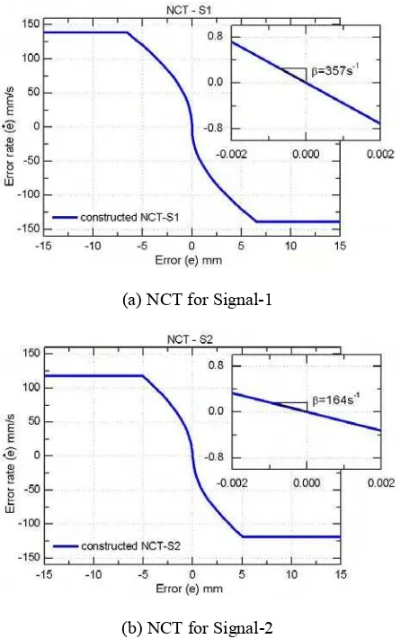
(a) NCT for Signal-1
(b) NCT for Signal-2
Fig. 5 Constructed NCTs from open-loop responses In order to achieve a practical controller, an easy and simple method in designing PI compensator is considered. When the characteristic of mechanism is considered in its controller, the stability of the control system will be considered and improve the positioning performance. Hence, the practical stability limit is introduced in determining the stability of control system during designing PI compensator.
The practical stability limit is found by driving the mechanism with the NCTF controller using only the proportional element. The value of proportional gain is increased until continuous oscillations are generated, which indicates the existence of instability. However, the non-damping mechanism tends to oscillate with any value of proportional gain. Thus, significant amplitude of oscillation needs to be decided for determining the suitable proportional gain. Once the continuous oscillation is over the decided threshold, the gain will be determined as maximum value of the proportional gain and it is referred as Kpu (actual ultimate proportional
gain). Same value of Kpu (Kpu = 0.25As/mm) is
determined for both different NCTs. The practical stability limit
ζ
pis given as⎟⎟
⎠
⎞
⎜⎜
⎝
⎛
=
n fm pu p
K
K
ω
ζ
2
u
t
12x
K
r f
fm
=
(4)The value of
ζ
pandω
nwill define the stability limit region for the PI compensator. In order to find the suitability ofζ
p, the value ofω
nT
k (where k = 1, …5) is increased and by using Eq.(4),ζ
pis determined. The compensator gains are calculated from Eq. (5).fm n p
K
K
=
2
ζω
fm n i
K
K
2
ω
=
(5)Fig. 6 illustrates the curve of practical stability limit which determined for both different NCTs. The chosen PI compensator is based on Signal-2 practical stability limit due to its better performance. The designed parameter Kp is set at 0.25 while Ki is 1.35. The
sampling time Ts is 0.4ms. The following positioning
results will show the effect of different constructed NCT in NCTF controller with the same value of PI compensator.
Fig. 6 Practical Stability limit
4. PERFORMANCE EVALUATION
In this section, the PTP positioning performance of the NCTF controller is evaluated. Performance comparisons have been done on both different NCTs with the compensator parameters shown before and conditional freeze integrator. A conditional freeze integrator is used to reduce the overshoot caused by the integrator windup [12].
Since the aim of modified input signal is to softly attenuate the mechanism motion as it approaches origin on the phase plane and follow reference trajectory, it is expected to reduce and/or avoid overshoot of the positioning system. A mechanism with non-damping characteristic is easier to cause the overshoot before stopping. Therefore, the ability of NCT-S2 to improve the transient response of the positioning system is a beneficial outcome of the design control system.
takes to reduce the error to less than 100nm.
Figure 7 shows the experimental and simulated responses of the NCTF closed-loop systems with NCT-S1 and NCT-S2 for the three (3) types of step inputs. The simulated responses, which are drawn in dashed- lines agree well with the experimental ones. However, marked vibration could be found in experimental results only. As illustrated obviously in the results, no matter the step input is changed from 1µm to 10mm, those positioning results of NCT-S2 have brought the impressive performance compare to NCT-S1. For the quantitative comparison, Table 2 details the averaged positioning results of 10 experiments under each NCT. The NCT-S1 which has inclination β of 357s-1 has taken shorter positioning time to reduce the error less than 100nm. The higher error rate and inclination near origin on phase plane are considered as the criteria to faster the positioning time in NCT-S1. However step responses of NCT-S1 yields the higher percentage of overshoot and the overshoot are too large when compare to step responses of NCT-S2. Moreover, higher overshoot is obviously found in the case of shorter step input. Furthermore, step responses with NCT-S2 which has smaller inclination produce the satisfied performance with lower overshoot. Even though step responses with NCT-S2 have to take longer positioning time to reduce the error less than 100nm, but the differences are small. Besides, the positioning time of NCT-S2 is shorter than NCT-S1 when the step input is 10µm. These results prove that the modified input signal (Signal-2) has a better performance than original one, especially in elimination of overshoot.
Table 2 Performance comparison
Step input NCT Positioning Time (s)
Percentage Overshoot (%)
1µm S1 0.014 23.104
S2 0.020 10.497
10µm S1 0.120 21.274
S2 0.053 8.581
1mm S1 0.974 6.148
S2 1.080 1.166
4mm S1 1.142 2.522
S2 1.436 0.437
10mm S1 1.113 1.235
S2 1.142 0.123
5. CONCLUSION
A practical control of non-friction mechanism for precision positioning is proposed. Clearly, the proposed NCTF controller design method is easy to design without known model parameters. The suitable current input for non-friction mechanism in open-loop condition is discussed. The modified input signal with smaller
trajectory. Comparative simulations and experimental results demonstrate the achievement of NCTF control system in non-friction mechanism. Furthermore, the NCTF controller is again proved to retain assurance of satisfied performance with the simple and easy design procedures in non-friction mechanism.
(a) Responses to 1µm step input
(b) Responses to 1mm step input
(c) Responses to 10mm step input
REFERENCES
[1] Wahyudi, Kaiji Sato, Akira Shimokohbe, “Characteristics of practical control for point-to-point (PTP) positioning systems: Effect of design parameters and actuator saturation on positioning performance,” Precision Engineering, Vol. 27, pp. 157-169, 2003.
[2] Umeno T, Kaneko T, Hori Y, “Robust servosystem design with two degrees of freedom and its application to novel motion control of robot manipulators,” IEEE Transactions On Industrial Electronics, Vol.40, No.5, pp.473-485, 1993. [3] Kempf C, Kobayashi S. “Disturbance observer and
feedforward design for a high-speed direct-drive positioning table,” IEEE Trans Control Syst Technol, Vol.7, No.5, pp.513-526, 1999
[4] Tan K.K., Lee H.L., Dou H.F., Chin S.J. and Zhao S., “Precision motion control with disturbance observer for pulsewidth-modulated-driven permanent-magnet linear motors,” IEEE Trans On Magnetics, Vol.39, No.3, pp.1813-1818, 2003 [5] Su Y. X., Zheng C. H. and Duan B. Y, “Automatic
disturbance rejection controller for precision motion control of permanent-magnet synchronous motors,” IEEE Trans on Industrial Electronics, Vol.52, No.3, pp.814-823, 2005
[6] Wu S., and Fu J., “Time-optimal control of servo system using PD algorithms,” JSME Int J Ser C, Vol.41, No.3, pp.384-390, 1998
[7] Ho-Seop Jeong and Chong-Won Lee, “Time delay control with state feedback for azimuth motion of the frictionless positioning device,” IEEE/ASME Trans on Mechatronics, Vol.2, No.3, pp.161-168, 1997
[8] Sankaranarayanan S. and Khorrami F., “Adaptive variable structure control and applications to friction compensations,” In Proceedings of the 36th IEEE Conference on Decision & Control, pp.4159-4164, 1997
[9] Yu-Feng Li and Jan Wikander, “Model reference discrete-time sliding mode control of linear servo motor precision servo systems,” Mechatronics, Vol.14, pp.835—851, 2004
[10]Sato K, Nakamoto K, Shimokohbe, “Practical control of precision positioning mechanism with friction,” Precision Engineering, Vol.28, pp.426-434, 2004
[11]Wahyudi, “New practical control of PTP positioning systems,” PhD Thesis, Tokyo Institute of Technology, 2002
[12]Sato K., “Robust and practical control for PTP positioning,” In Proc. ICPT2004, pp.394-395, 2004 [13]Wahyudi, Sato K, Shimokohbe A, “Robustness
evaluation of new practical control for PTP positioning systems,” International conference on advanced intelligent mechatronics proceedings, pp.843-848, 2001
[14]Sato K, Guilherme Jorge Maeda, “Practical ultraprecision positioning of a ball screw mechanism,” International Journal of Precision
Engineering and Manufacturing, Vol.9, No.2 pp.44-49, 2008