Faculty of Manufacturing Engineering
SOL GEL PROCESS OF COBALT NANOPARTICLES
PREPARATION AS EFFECTIVE CATALYST FOR
CNT GROWTH PERFORMANCE
NOR NAJIHAH BINTI ZULKAPLI
MASTER OF SCIENCE IN MANUFACTURING
ENGINEERING
Faculty of Manufacturing Engineering
SOL GEL PROCESS OF COBALT NANOPARTICLES
PREPARATION AS EFFECTIVE CATALYST FOR CNT GROWTH
PERFORMANCE
Nor Najihah binti Zulkapli
Master of Science in Manufacturing Engineering
SOL GEL PROCESS OF COBALT NANOPARTICLES PREPARATION AS EFFECTIVE CATALYST FOR CNT GROWTH PERFORMANCE
NOR NAJIHAH BINTI ZULKAPLI
A thesis submitted
In fulfilment of the requirements for the degree of Master of Science In Manufacturing Engineering
FACULTY OF MANUFACTURING ENGINEERING
UNIVERSITI TEKNIKAL MALAYSIA MELAKA
DECLARATION
I declare that this thesis entitle “Sol Gel Process of Cobalt Nanoparticles Preparation as Effective Catalyst for CNT Growth Performance“ is the result of my own research except as cited in the references. The thesis has not been accepted for any degree and is not concurrently submitted in candidature of any other degree.
APPROVAL
I hereby declare that I have read this thesis and my opinion this thesis is sufficient in terms of scope and quality for the award of Master of Science in Manufacturing Engineering (Advanced Materials).
DEDICATION
ABSTRACT
Carbon nanotube (CNT) is a well known structure that has extraordinary properties and widely used in many application. The presence of metal catalyst is needed for CNT growth by CVD technique. The properties of as-grown CNT is depends on the properties of metal catalyst. The aim of this project was to produce cobalt (Co) catalyst by spin coating process for carbon nanotube (CNT) growth. It was targeting to study the catalyst thin film formation by using solution process, analyze the catalyst nanoparticles transformation from the deposited thin film and confirm the structural properties of as-grown CNT by Raman spectroscopy. This project was divided into two major parts. The first part was catalyst preparation and the second part was CNT growth. The Co catalyst was prepared by spin coating and heat treatment process. The spin speed of spin coating was varied from 6500 rpm to 8000 rpm with 500 rpm interval and spinning duration of 60 s. The post-heat treatment temperature was varied from 450 ⁰C to 600 ⁰C with interval of 50 ⁰C and heating duration of 10 minutes. The Co catalyst nanoparticles formed after heat treatment process then being used for CNT growth by alcohol catalytic CVD (ACCVD) technique. The CVD processing temperature was varied in range of 650-750 ⁰C with 25 ⁰C interval. The CVD processing time was fixed for 15 minutes. The Co catalyst and its nanoparticles were characterized by field emission scanning electron microscopy (FESEM), X-ray diffraction (XRD) and X-ray photoelectron spectroscopy (XPS) while the structural properties of the as-grown CNT was studied by Raman spectroscopy. The thickness of Co catalyst thin film was decreasing by the increasing of spin speed. Based on four varied value of spin speed; 6500, 7000, 7500 and 8000 rpm, the optimum spin speed with smallest thickness of Co catalyst thin film, 12.1 nm, was at 8000 rpm. Besides, the average size of Co nanoparticle was increased by the increasing of post-heat treatment temperature. The optimum temperature was found at 450 ⁰C with 10.64 nm average size of Co nanoparticles. The Co catalyst thin film was confirmed by XRD and XPS analysis to have CoO compound structure while the Co catalyst nanoparticles was in Co3O4 structure. Then, 700 ⁰C was
found to be the optimum CVD processing temperature for the CNT grown on spin coated Co catalyst nanoparticles with the highest IG/ID ratio of 6.398. Additionally, the presence
of SWCNT structure was confirmed by the presence of RBM peak in range of 100-400 cm -1 Raman shift measured by Raman spectroscopy. The measured SWCNT tube diameters
were less than 1.5 nm. Hence, it can be concluded that the thickness of Co catalyst thin film can be controlled by controlling the spin speed of spin coating. Optimum post-heat and CVD processing temperature is crucial for Co catalyst nanoparticles formation and obtaining good quality of CNT. The as-grown CNT in this project has high potential in electronic device application due to the smaller SWCNT tube diameter and good quality.
ABSTRAK
Tiub nano karbon (CNT) adalah sebuah struktur terkenal yang mempunyai ciri-ciri yang luar biasa dan digunakan secara meluas dalam pelbagai aplikasi. Kehadiran pemangkin logam diperlukan untuk penghasilan CNT melalui teknik CVD. Sifat-sifat CNT yang terhasil bergantung kepada sifat-sifat pemangkin logam yang digunakan. Tujuan projek ini adalah untuk menghasilkan kobalt (Co) pemangkin melalui proses salutan putaran untuk penghasilan CNT. Ia menyasarkan untuk mengkaji pembentukan filem pemangkin yang nipis dengan menggunakan solution process, menganalisis transformasi filem pemangkin yang nipis tersebut kepada bentuk nanopartikel dan mengesahkan sifat-sifat struktur CNT yang terhasil dengan menggunakan Raman spektroskopi. Projek ini telah dibahagikan kepada dua bahagian utama. Bahagian pertama adalah penghasilan pemangkin dan bahagian kedua adalah penghasilan CNT. Co Pemangkin telah dihasilkan melalui proses salutan putaran dan proses rawatan haba. Kelajuan putaran salutan putaran telah dimanipulasikan dari 6500 rpm ke 8000 rpm dengan selang 500 rpm dan tempoh berputar 60 s. Suhu rawatan selepas haba telah dimanipulasikan dari 450 ⁰C 600 ⁰C dengan selang 50 ⁰C dengan tempoh pemanasan selama 10 minit. Nanopartikel pemangkin yang terbentuk selepas melalui proses rawatan haba kemudiannya digunakan untuk penghasilan CNT dengan teknik alkohol pemangkin CVD (ACCVD). Suhu pemprosesan CVD telah dimanipulasikan dalam lingkungan 650-750 ⁰C dengan selang 25 ⁰C. Masa pemprosesan CVD telah ditetapkan selama 15 minit. Bersama pemangkin dan nanopartikel yang telah dianalisis oleh pelepasan bidang mikroskop imbasan elektron (FESEM), sinar-X pembelauan (XRD) dan sinar-X fotoelektron spektroskopi (XPS) manakala sifat-sifat struktur yang CNT yang terhasil telah dikaji dengan spektroskopi Raman. Ketebalan Co pemangkin filem nipis telah berkurangan dengan peningkatan kelajuan putaran. Berdasarkan empat nilai yang dimanipulasikan daripada kelajuan putaran; 6500, 7000, 7500 dan 8000 rpm, kelajuan putaran optimum dengan ketebalan terkecil pemangkin Co filem nipis, 12.1 nm, adalah pada 8000 rpm. Selain itu, saiz purata Co nanopartikel telah meningkat dengan peningkatan suhu rawatan selepas haba. Suhu optimum adalah pada 450 ⁰C dengan 10.64 saiz purata nm Co nanopartikel. Filem pemangkin yang nipis tersebut telah disahkan oleh XRD dan XPS analisis mempunyai struktur CoO kompaun manakala Co nanopartikel pemangkin adalah dalam struktur Co3O4. Kemudian, 700 ⁰C
didapati sebagai suhu optimum pemprosesan CVD bagi CNT yang terhasil daripada Co nanopartikel dengan nisbah IG/ID tertinggi iaitu 6.398. Selain itu, kehadiran struktur
single-walled CNT (SWCNT) disahkan dengan kehadiran puncak RBM dalam julat 100-400 cm-1 yang diukur dengan spektroskopi Raman. Diameter tiub SWCNT yang diukur adalah kurang daripada 1.5 nm. Kesimpulannya, ketebalan Co filem pemangkin yang nipis boleh dikawal dengan mengawal kelajuan putaran salutan putaran. CNT yang terhasil dalam projek ini berpotensi tinggi dalam aplikasi peranti elektronik kerana mempunyai diameter tiub SWCNT yang lebih kecil dan kualiti yang baik.
ACKNOWLEDGEMENT
First and foremost, I would like to take this opportunity to express my sincere acknowledgement to my supervisor, Dr. Mohd Asyadi Azam bin Mohd Abid, from the Faculty of Manufacturing Engineering Universiti Teknikal Malaysia Melaka (UTeM) for his essential supervision, support and encouragement towards the completion of this thesis. I also would like to express my greatest gratitude to Profesor Madya Dr. Mohd Warikh bin Abd Rashid from Faculty of Manufacturing Engineering, co-supervisor of this project, for his advice and suggestions in completing this project. Special thanks to Ministry of Higher Education (MOE), Malaysia under the Exploratory Research Grant Scheme (ERGS) with research grant numbered E00032 and MyBrain15 program for the financial support throughout this project. Particularly, I would also like to express my deepest gratitude to Mr. Hairulhisham, the assistant engineer from Polymer Laboratory, Mrs. Siti Aisah and Mr. Mohd Nazri, assistant engineers from Metrology Laboratory for their assistance, time spent and efforts in the entire lab and analysis works.
Special thanks to all students under supervision of Engr. Dr. Mohd Asyadi Azam, all my peers, my parents and siblings for their moral support in completing this degree. Lastly, thank you to everyone who had been to the crucial parts of realization of this project. Not forgetting, my humble apology as it is beyond my reach personally mentioned those who are involved directly or indirectly one to one.
2.6.3 X-ray Photoelectron Spectroscopy (XPS) 40
3.3.2 Carbon Nanotube Grown from Cobalt Catalyst Nanoparticles 56
3.4 Summary of Methodology 59
4.3.1 Carbon Nanotube Growth from Cobalt Catalyst Nanoparticles 78
processing temperature
4.4 Tabulated RBM peaks with varied CVD processing temperature 86
4.5 Tabulated SWCNT tube diameters 86
4.6 Percentage of carbon on silicon substrate 87
4.7 Raman shift and intensity of G-band and Si-band according to 88
the selected CVD processing temperatures 4.8 SWCNT loading on SiO2/Si substrate 90
4.9 Raman shift and intensity of G-band and dominant RBM peak 90 according to the selected CVD processing temperatures
LIST OF FIGURES
FIGURES TITLE PAGE
1.1 Basic structure of carbon nanotube; (a) graphene sheet, (b) cylindrical 3 shape with open ends and (c) cylindrical shape with closed ends
(Hawk's Perch Technical Writing, 2014)
1.2 Three different orientation of cylindrical shape of carbon nanotube with 4 open ends, (a) zigzag, (b) armchair and (c) chiral (drawing by using BIOVIA Materials Studio 7.0)
2.1 Steps in sol-gel process (Rath, 2005) 11
2.2 Example of temperature profiles for annealing process (Azam et al., 2014) 15 2.3 Crystallographic structure of Co, (a) fcc and (b) hcp (Winter, 2015; 18
Mills, 2014)
2.4 Four steps involved in spin coating process (Azam et al., 2014; 21 Bornside et al., 1987)
2.5 Schematic image of the growth alignment, tip-growth and root-growth 28 models (red balls: catalyst particles; blue balls: carbon atoms; brown: substrate) (Hayashi et al., 2003)
2.6 (a) Schematic diagram of ACCVD system and (b) close-up schematic 32 of sample holder (Azam et al., 2013)
2.7 Example of SEM cross section of samples containing 0.2 g/(g PAN) 37
cobalt acetate at room temperature and annealed at 200, 400, 600, 800 and 1000 °C. The length of the thickness indicators (white stripes) was calculated by taking into account the tilting of the films. (Darányi et al., 2011)
2.8 Example of SEM top view for the surface morphology of the Co 38
catalytic nanoparticles formed on quartz substrate after the heat and NH3 pre-treatments at 800 ⁰C. (SEM, JEOL JSM-6400 microscope) (Terrado et al., 2006) 2.9 The example of XRD patterns on crystallographic structure of Co 39
ULVAC, Synthesis Laboratory of FKP, UTeM)
3.11 Flow process of carbon nanotube growth by high-vacuum CVD 52
furnace (MILA-3000) 3.12 CVD processing temperature profile (TCVD is varied in range of 53
650-750 ⁰C with interval of 25 ⁰C) 3.13 Digital image of UniRAM-3500 Raman spectroscopy 57
3.14 The schematic of Raman laser line 57
3.15 Schematic illustration of the Raman laser spots position on substrate 58
3.16 Ideal path for achieving objectives 59
4.1 FESEM images of the cross-sectional view of Co catalyst thin film 62
spin-coated on the SiO2/Si substrates with varied spin speed; (a) 6500 rpm, (b) 7000 rpm, (c) 7500 rpm and (d) 8000 rpm. The samples are cross-sectional, tilted to 45° and in different scales and magnification 4.2 The histograms of Co catalyst thin films thickness with the spin 64
speed of (a) 6500 rpm, (b) 7000 rpm, (c) 7500 rpm, (d) 8000 rpm and (e) graph of average thickness of Co catalyst thin films at four different spin speeds 4.3 XRD spectrum of CoO(OH) pre-heated at 250 ⁰C for 5 minutes 65
4.4 XPS spectra of the pre-heated Co catalyst thin film for (a) survey 66
spectrum, (b) narrow spectrum of Co 2p of Co oxide system. Note that asterisks *represent the shake-up satellite peaks of Co 2p 4.5 Film thinning mechanism by spin coating process 67
4.6 FESEM top view images of Co catalyst nanoparticles heat treated by 71 various post-heat treatment temperature; (a) 450 ⁰C, (b) 500 ⁰C, (c) 550 ⁰C
4.7 The histograms of Co catalyst nanoparticle size with the post-heat 72 treatment of (a) 450 ⁰C, (b) 500 ⁰C, (c) 550 ⁰C, (d) 600 ⁰C and (e) graph of average particle size of Co catalyst nanoparticles at four different post-heat treatment
4.8 XRD pattern of Co3O4 post-heated at 600 ⁰C for 10 minutes 74
4.9 XPS spectra of the post-heated Co catalyst nanoparticles for 75 (a)survey spectrum, (b) narrow spectrum of Co 2p of Co oxide system.
Note that asterisks * represent the shake-up satellite peaks of Co 2p
4.10 Comparison of Co 2p narrow spectra for pre-heated Co catalyst thin 76 film and post-heated Co catalyst nanoparticles. Note that asterisks
* represent the shake-up satellite peaks of Co 2p
4.11 Cobalt catalyst nanoparticles formation mechanism by post-heat 77 processing temperatures (in range of 100-400 cm-1)
4.16 Plotted percentage of carbon content on SiO2/Si substrate 88
4.17 Plotted SWCNT loading on SiO2/Si substrate 89
4.18 Illustration of SWCNT growth model for (a) based-growth and 93 (b) tip-growth
LIST OF ABBREVIATIONS CVD Chemical vapour deposition
ACCVD Alcohol catalytic chemical vapour deposition WACVD Water-assisted chemical vapour deposition PECVD Plasma-enhanced chemical vapour deposition FCCVD Floating catalyst chemical vapour deposition TCVD Thermal chemical vapour deposition
PVD Physical vapour deposition
Co Cobalt
FESEM Field emission scanning electron microscopy
XRD X-ray diffraction
XPS X-ray photoelectron spectroscopy TEM Transmission electron microscopy
HR-TEM High resolution transmission electron microscopy
Si Silicon
BE Binding energy
IG/ID G-band intensity over D-band intensity
RBM Radial breathing mode
LIST OF PUBLICATIONS
(i) Peer Reviewed Journals
1. Zulkapli, N. N., Azam, M. A., Zubir, N. M. A. M., Ithnin, N. A. and Rashid, M. W. A., 2015. A Simple and Room Temperature Sol-gel Process for the Fabrication of Cobalt Nanoparticles as an Effective Catalyst for Carbon Nanotube Growth. RSC Advances, 5(116), pp.95872-95881.
2. Zulkapli, N. N., Ithnin, N. A., Azren, N. M. and Azam, M. A., 2015. Raman Spectra Analysis of Single-walled Carbon Nanotube Grown from Spin-coated Cobalt Catalyst at Different Temperatures. Journal of Engineering and Applied Sciences, 11(3), pp.1550-1554.
3. Zulkapli, N.N., Manaf, M. E. A., Maulod, H. E. A., Abdul Manaf, N. S., Raja Seman, R. N. A., Bistamam, M. S. A., Talib, E. and Azam, M. A., 2015. Control of Cobalt Catalyst Thin Film Thickness by Varying Spin Speed in Spin Coating towards Carbon Nanotube Growth. Applied Mechanics and Materials, 761,
pp.421–425.
4. Azam, M. A., Zulkapli, N. N., Nawi, Z. M. and Azren, N. M., 2014. Systematic review of catalyst nanoparticles synthesized by solution process: towards efficient carbon nanotube growth. Journal of Sol-Gel Science and Technology, 73, pp.1-17.
5. Azam, M. A., Nawi, Z. M., Azren, N. M. and Zulkapli, N. N., 2015. Synthesis of Fe-Catalyst Nanoparticles by Solution Process towards Carbon Nanotube Growth.
Materials Technology: Advanced Performance Materials, 30(A1), pp. A8-A13.
6. Raja Seman, R.N.A., Munawar, R. F., Razak, J. A., Zulkapli, N. N., Bistamam, M. S. A., Talib, E., Tunku Kudin, T. I., Abdul Manaf, N. S. and Azam, M. A., 2015. Cyclic Voltammetry Analysis of Carbon Based Electrochemical Capacitor in Aqueous Electrolytes. Applied Mechanics and Materials, 761, pp.452–456.
7. Talib, E., Lau, K. –T., Zaimi, M., Bistamam, M. S. A., Abdul Manaf, N. S., Raja Seman, R. N. A., Zulkapli, N. N. and Azam, M. A., 2015. Electrochemical Performance of Multi Walled Carbon Nanotube and Graphene Composite Films Using Electrophoretic Deposition Technique. Applied Mechanics and Materials,
761, pp.468–472.
8. Azam, M. A., Hassan, A., Mohamad, N., Talib, E., Abdul Manaf, N. S., Zulkapli, N. N., Raja Seman, R. N. A. and Bistamam, M. S. A., 2015. Fabrication of Activated Carbon Filled Epoxidized Natural Rubber Composite Using Solvent Casting Method. Applied Mechanics and Materials, 761, pp. 426-430
(ii) Conferences
1. International Symposium on Functional Materials (ISFM) 2014 (Poster), Singapore, 4-7th Aug 2014
• Title : Synthesis of Cobalt Catalyst Nanoparticles by Solution Process for Carbon Nanotube Growth
2. International Symposium on Advanced Functional Materials (ISAFM) 2014 (Oral), Kuala Lumpur, 1-2th Aug 2014
• Title : Synthesis of Fe-Catalyst Nanoparticles by Solution Process towards CNT Growth
3. International Design and Concurrent Engineering (iDECON) 2014 (Oral), Avillion Legacy Hotel, Melaka, 22-23rd Sept 2014
• Title : Control of Cobalt Catalyst Thin Film Thickness by Varying Spin Speed in Spin Coating towards Carbon Nanotube Growth
4. Malaysian Technical Universities Conference on Engineering and Technology (MUCET) 2015 (Oral), KSL Resort Hotel, Johor Bahru, 11-13th October 2015
• Title: Raman Spectra Analysis of Single-Walled Carbon Nanotube Grown from Spin-Coated Cobalt Catalyst at Different Temperatures
CHAPTER 1
INTRODUCTION
1.0 Background
This is the beginning of thesis content. In this chapter, it consists of four parts. The first part is the introduction of the carbon nanotube (CNT), its structure, the growth and the importance of catalyst in CNT growth. Then, it is followed by the problem statement of the project, objectives and closed with scopes of this project.
1.1 Introduction
Global industries have been shifted from micro technology to nanotechnology. Nanotechnology is a technology that has been spread into many fields of studies such as sciences, engineering, medicine and many more. The expended technology is all about producing and manipulating small objects as well as building from extremely small objects which is less than 100 nm. By making things smaller, it gives merit to the economic and technology such as cut-off the production cost by a mass production of products. This is due to only small quantity of the extraordinary properties of nanomaterials is needed in a particular production. Thus, the shortage of nature sources can be solved respectively.
CNT is the example of nanomaterial that has been widely used in many fields of application. It was being used in electronic device, energy storage device and also being used as a reinforcement material in composite. CNT is just a tiny structure in nano-scales in which the diameter approximately 10,000 times smaller than human hair but yet it can
give huge impact on science and technology. Ever since the existence of this material has been exposed by Sumio Iijima in 1991 and acknowledged by the researchers (Bethune et al., 1993; Yacaman et al., 1993; Amelinckx et al., 1994; Ivanov et al., 1994; Thess et al., 1996; Hernadi et al., 2000; Ermakova and Ermakov, 2002) due to the unique structure as well as the extraordinary properties; such as high electrical conductivity and good electronic properties in work function and the contact resistance with metals, it has been an interesting subject to be explored up till this century (Iijima, 1991; Hu et al., 2009).
According to Harris (2009), CNT is a structure formed from a repeated chemical element of carbon (C) in which bonded by covalent bonding. Covalent bonding is a strong chemical bond that involves in sharing electron pairs between atoms. The three famous allotropes of carbon are 2D-graphite, 3D-diamond and amorphous carbon. The most well-known application of graphite was as cores in pencils. It has been used after lead due to the poisonous issue on lead back then. The second allotrope which is usually used along with the ring is the most favoured by women and also quite expensive. It is also the hardest nature material due to its diamond lattice arrangement. The highest hardness own by this structure leads to the restructured as synthetic diamond that being used as cutting and polishing tools in industries. Another form of carbon was discovered by Kroto is 0D-fullerence (Kroto, 2001). Due to that finding, nanotubes can be classified as one of the fullerence’s family member.
CNT can be classified according to its growth alignment and helicity. There are two types of CNT based on growth alignment; 1) entangled CNT and 2) aligned CNT. Entangled CNT is the CNT that grown in random alignment. Aligned CNT is the CNT that grown either in vertical or horizontal alignment. The most favoured CNT based on the
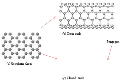
growth direction for electronic devices is vertically aligned CNT (VA-CNT) instead of horizontally aligned CNT (HA-CNT) because it can improve the device capacitance performance (Yuan et al., 2008; Murakami et al., 2004; Huang et al., 2003). Moreover, for the CNT classified by the helicity, there are single-walled CNT (SWCNT) and multi-walled CNT (MWCNT) (Azam et al., 2011). As illustrated in Figure 1.1, the basic structure for both types of CNT is 2D-graphene sheet. SWCNT can be obtained by wrapping a 2D-graphene sheet into a seamless cylindrical structure or by elongating a Bulkyball or C60 to be a tubular structure, (Harris, 2009; Azam et al., 2013; Iijima and
Ichihashi, 1993; Bethune et al., 1993).
Figure 1.1: Basic structure of carbon nanotube; (a) graphene sheet, (b) cylindrical shape with open ends and (c) cylindrical shape with closed ends (Hawk's Perch Technical
Writing, 2014)
The graphene sheet can be wrapped by three orientations; 1) zigzag, 2) armchair and 3) chiral (Harris, 2009; Liu et al., 2013). The different wrapping orientation as illustrated in Figure 1.2 gives different electrical property in which can be employed in
Pentagon (b) Open ends
(c) Closed ends (a) Graphene sheet