UNIVERSITI TEKNIKAL MALAYSIA MELAKA
DEVELOPMENT OF CONTROLLER FOR GROUND WATER
WELL BY USING ARDUINO
This report is submitted in accordance with requirement of Universiti Teknikal Malaysia Melaka (UTeM) for the Bachelor Degree of Electronic Engineering
Technology (Industrial Electronic) (Hons.)
by
MOHAMAD NAJIB FAHMI BIN AHMAD PISOL B071210398
911001-02-5259
i
DECLARATION
I hereby, declared this report entitled “Development of Controller for Ground Water Well by using Arduino” is the results of my own research except as cited in references.
Signature :……….
ii
APPROVAL
This report is submitted to the Faculty of Engineering Technology of UTeM as a partial fulfillment of the requirements for the degree of Bachelor of Engineering Technology
(BACHELOR OF ELECTRONICS ENGINEERING TECHNOLOGY) (INDUSTRIAL
ELECTRONICS.). The member of the supervisory is as follow:
iii
ABSTRAK
iv
ABSTRACT
v
DEDICATIONS
To my beloved parents
Ahmad Pisol Bin Talid and Nadziroh Binti Din
To my lecturer and supervisor, for her guidance and encouragement Cik Siti Halma Binti Johari
vi
ACKNOWLEDGEMENT
vii
List ABBREVIATIONS, SYMBOLS AND NOMENCLATURES xii
CHAPTER 1: INTRODUCTION 1
2.4 Communication protocol 9
2.5 Working principle 10
2.5.1 Arduino UNO R3 11
2.5.2 LCD display 12
2.5.3 Peristaltic pump 14
viii
3.4 Hardware Development 20
3.4.1 Circuit design 20
3.4.2 SIM900 GSM Development 22
3.4.3 Developing the SIM900 GSM Interface 22
3.5 Outline of Report 23
CHAPTER 4: RESULT AND DISCUSSION 24
4.1 Introduction 24
CHAPTER 5: CONCLUSION & FUTURE WORK 34
5.2 Conclusion 34
5.3 Future Work 35
APPENDIX A 36
ix
LIST OF TABLE
Table 2.1: Arduino Specification 12
Table 2.2: Interfacing Arduino to LCD 13
x
Figures 2.5: Atmega 168/328 communication Mapping 9 Figures 2.6: Ground water well system block 10
Figures 2.7: Arduino UNO R3 board 11
Figures 2.8: LCD display 13
Figures 2.9: Peristaltic pump 14
Figures 3.1: Flow chart project methodology 17
Figures 3.2: Ground Water Well block diagram 19 Figures 3.3: Ground Water Well circuit using Proteus 21
Figures 3.4: System architecture 23
Figures 4.1: LCD display water level is and motor is ON 25
Figures 4.2: Using Proteus software LCD display water level is and
motor is ON 25
Figures 4.3: LCD display water level is half and motor is ON 26 Figures 4.4: Using Proteus software LCD display water level is half and
motor is ON 26
Figures 4.5: LCD display water level is and motor is ON 27
Figures 4.6: Using Proteus software LCD display water level is and
motor is ON 27
Figures 4.7: LCD display water level is Full and motor is OFF 28 Figures 4.8: Using Proteus software LCD display water level is full and
motor is OFF 28
xi
Figures 4.10: The Arduino UNO is connected to Power Supply 30 Figures 4.11: Arduino UNO connected to Sim900 GSM 31 Figures 4.12: Arduino UNO connected to the Water Level Circuit 31
Figures 4.13: How to upload the programming 32
xii
LIST OF ABBREVIATIONS, SYMBOLS AND
NOMENCLATURE
PC - Personal Computer
USB - Universal Serial Bus
ICSP - In Circuit Serial Programming
AC - Analog Circuit
DC - Digital Circuit
GND - Ground
1
CHAPTER 1
INTRODUCTION
This chapter will cover the detail explaination of the introduction of project background. Some of the discussion is about problem statement, objective project, the scope, and limitation of this project.
1.1 Background Project
2
Upon reaching the critical water level in the tank, an SMS is sent through GSM module to the technician incharge for further action.
1.2 Problem Statement
Most of people have a problem to have clean water especially after flood. Recent development of controller for ground water well in Malaysia is driven by the expansion of industries and population growth in remote areas where connection to the main water supply is not available. Alternatively the ground water becomes an alternative source of water supply that can be use in every residence.
1.3 Objective
The objectives of this project are as listed below:
1) To study interconnection of mobile device environment and Sim900 GSM/GPRS shield based on Arduino UNO R3 board.
2) To develop prototype of ground water well control by Arduino UNO R3. 3) To analyse the performance of ground water control by Arduino UNO R3.
1.4 Scope and limitation
3
1.5 Outline of report
4
CHAPTER 2
LITERATURE REVIEW
In this section, will discuss about any fact that might be helping to developing the ground water well. The facts can be an article, journal, book or paper review. Previous works done by other research are also explained.
2.1 Introduction
5
especially for slim and compact demand of design.(NJS Consultants Published on Jul 20, 2014).
2.2 Previous research
“Control and monitoring system of Small Water Plant” presented by (Koval, Feci, & Jakab, 2013) in their research paper, the main goals of research in this area were:
Versatility of the solution for remote administration and monitoring the sensor network based on Arduino Development Environmnet.
Reliability in export readings to a central data repository.
Price affordability of solution with respect to SOHO solutions.
6
2.3 System Design
In the proposed network of set Arduino UNO R3 and Sim900 GSM device, this system operates in a condition water detector which is in low level or high level water. The system is developed under GSM platform to monitor and control ground water well via Arduino UNO R3 board. The Arduino UNO R3 function as base board to received programming code from Arduino Software. The arduino controller is set as main board to receive input sensor from water level sensor. If it receives a command to instruct the arduino to change the on/off pump status, the arduino sends a command to the controller through the Sim900 GSM module. Then the Sim900 GSM board monitoring the level of water and send the warning to the smartphone. When the water level at high the Arduino UNO R3 executes the controls pump operation (off).
7
Figure 2.1: Arduino Uno circuit connection. (Santos, n.d.)
8
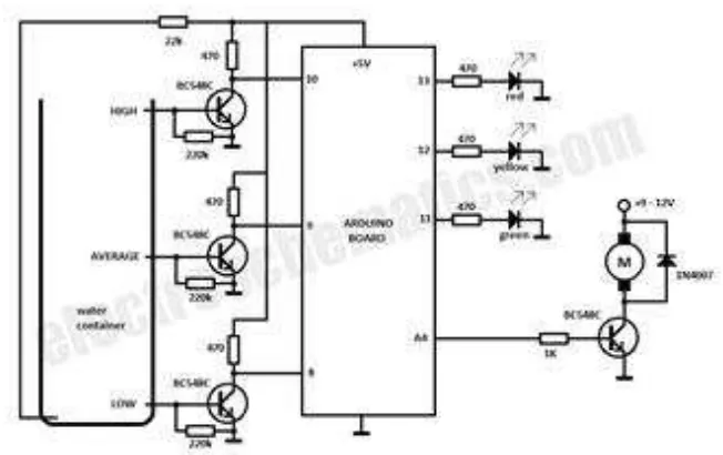
Figure 2.3: Water level indicator circuit (www.Electro schematic.com)
9
2.4 Communication protocol
Arduino UNO R3 serial is used to communicated with Arduino board and other devices. Basically the Arduino UNO R3 board actually have at least one serial port which is knows as UART or USART. The input and output pin has each 14 digital pin on the Arduino UNO R3 can be used. The Arduino basically working at 5 Volts. And every pin in Arduino can provide 20 mA operating condition. There several pin in Arduino has specialized function which is the serial actually communicates on digital pin 0 (RX) and pin 1 (TX). For pin 2 and 3 function as the interrupt on the low value, a rising or the falling edge, or can change the value. And for pin 3,5,6,9,10,and 11 act as PWM. It provide 8 bit PWM output with analogWrite() function. Pin 13 is built in LED driven, when the pin is HIGH the LED ON and whem pin is LOW the LED is OFF. A0,A1,A2,A3,A4 and A5 it is Analog input is TWI communication that using wire library that provide 10 bit resolution
10
The Arduino UNO R3 provide UART TTL (5V) serial communication, the board channel for RX and TX serial communication over USB appear as virtual port to software. The Arduino Software (IDE) includes serial monitor which allows simple textual data to sen on the board. A SoftwareSerial library allow serial communication on any Arduino digital pin.
2.5 Working principle
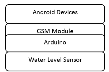
There are three functional components in this project include bluetooth devices, water level sensors and the water pump. Thus the Arduino Board is programmed using Arduino IDE software. The water level sensor is to sense present water tank. The water pump supplies water to the plants. Figure 2.5 show system block for ground water well.
Figure 2.6: Ground water well System block
This project uses Arduino UNO R3 to control the motor. Follow the schematic to connect the Arduino to the motor driver, and the driver to the water pump. The motor can be driven by 12 Volt battery. The water level indicator will sense the present of water by using water level sensor, and measure the level of water and send the signal to Arduino Board. The motor pump will supply the water to the water tank until desired water level reached. The GSM module will send the warning mesej to the smartphone when the water level reach to every level in water tank.
Android Devices
11
2.5.1 Arduino UNO R3
The Arduino UNO R3 is a microcontroller board based on the Atmega328. It has 14 digital input/output pins (of which 6 can be used as PWM output), 6 analog inputs, a 16 MHz ceramic resonator, a USB connection, a power jack, an ICSP header, and a reset button. It contains everything needed to support the microcontroller, simply connect it to a computer with a USB cable or power it with a AC to DC adapter or battery to get started. The picture of Arduino UNO R3 is show in Figure 2.6.
Figure 2.7: Arduino Uno board (Science & Engineering, 2014)