DOI: 10.12928/TELKOMNIKA.v14i3.3512 846
Internet Protocol Based Satellite On-Board System
Emir Husni*, Nazmi Febrian, Angga Putra
School of Electrical Engineering and Informatics, Institut Teknologi Bandung, Jl. Ganesha 10, Bandung, telp +62-22-2500960
*Corresponding author, e-mail: [email protected], [email protected], [email protected]
Abstract
The reliability of satellite data communication can be enhanced by designing two subsystems involving data communication among subsystem and data communication between satellie and Ground Station (GS). In this paper, Error Control Coding (ECC) is applied in satellite data communication with Automatic Repeat Request (ARQ) method. Further, bit error checking uses the calculation of 15 bit Cyclic Redundancy Check (CRC) Controller Area Network (CAN) standard. The calculation of CRC is attached in CAN frame over IP communication protocol between primary OBC and secondary OBC. OBC is designed by implementing Triple Modular Redundant system on a Linux-based operating system. The CAN frame over IP simulation with manual input is found to correct all corrupted data. When the simulation uses NetEM, the system corrects 100 % data with 0-10 % value of corruption with maximum time transfer of 84.472 seconds. ION DTN is also found to correct all corrupted data with values from 0 to 2 % and maximum delay at an altitude of 50,000 kilometer orbit using NetEm for TMTC mission. The testing results show that the system will keep carrying out its mission as long as a fault does not occur on all three OBC at the same time.
Keywords: OBC, ECC, CAN frame over IP, CRC, triple modular redundant
Copyright © 2016 Universitas Ahmad Dahlan. All rights reserved.
1. Introduction
Faults in data transmission at an altitude of satellite orbit can be caused by several factors, such as long delay, intermittent connectivity and single event effects [1-3]. This may further lead to non-destructive and destructive failures in the satellite system, such as bit error in data transmission and current leakage in hardware [4-6]. In space, Single Event Upset (SEU) can generate bit errors because particle radiation can flip the memory cell of satellite electronic devices [7, 8]. In addition, Single Event Latch-up (SEL) can cause hard error that leads to hardware damage in the satellite system. To overcome these problems, it is important that the system be made fault-tolerant.
In this study, a fault-tolerant system is designed using Triple Modular Redundancy (TMR), Error Correction Coding (ECC) and Automatic Repeat Request (ARQ) implemented on a Linux-Based On-Board Computer using Intel Galileo Generation 1. TMR is implemented using three Intel Galileo modules which are interconnected via a passive switch.
ECC and ARQ were selected in this study to overcome the problem of data transmission in space. After a failure is detected, the OBC can send repeated requests for the sending of data which has been encapsulated. With this method, the data read by sensors in the satellites is guaranteed to be delivered down to the Ground Station (GS). Through the ECC system arranged, it is expected that the data obtained by the satellites can be forwarded to the GS without distortion or failure. In addition, ECC in satellites is designed to improve their fault-tolerant capabilities.
The system is also designed to accommodate processing data transmission between the satellite and the GS with a long delay and intermittent connectivity. The problem can be compounded by the altitude of satellite orbit that reach thousand kilometers from the earth’s surface. Delay and intermittent connectivity make the data transmission at uplink and downlink become a failure. Data to be transmitted have to be separated for sending one by one to GS. The process can be done automatically using the DTN-based communication using IP.
(IoT), in which all sensors and other subsystems are connected to an inter-networking system using IP.
The key to implementing this design is to have On-Board Computers (OBC), which are based on on-board Internet, as the main component of the satellite data processing. On-board Internet can manage and control all smart devices that connect to the satellite without requiring any specific data format. This then grant users more flexibility and accessibility to control the satellite via the Internet.
2. Basic Principle
2.1. Controller Area Network (CAN) Protocol
Controller Area Network (CAN) is a serial communication protocol for data transmission standard in electric vehicle subsystem, such as Electrical Control Units (ECU) [9, 10]. Besides in vehicle application, CAN also has been implemented as a Satellite bus communication [11, 12] and Remote Terminal Unit (RTU) in Supervisory Control and Data Acquisition (SCADA) [13]. CAN is a multi-master communication network in which each node has a specific identifier (ID). CAN protocol can support real-time communication efficiently with high level security. The CAN frame has several fields: Arbitration field, Control field, the Data field, CRC field and ACK field. There are two different formats of arbitration field based on its length of the ID-standard frames have 11-bit identifier and Extended Frames have 29-bit identifier.
In the control field, there is a single bit box called IDE which differs from CAN standard, which has 8-byte data field. However, due to increasing bandwidth requirements, CAN was improved by adding payloads of size > 8 bytes.
In 2012, CAN with Flexible Data Rate was launched as a new standard of CAN communication. CAN with Flexible Data Rate or CAN FD has 64-byte data field. CAN data transmission has a maximum rate of 1 Mbps. In CAN-FD frames, the CRC field serve to validate the data transmission. CAN-FD requires 17-bit or 21-bit of CRC to check the data transmission. CRC field has a sequence involving the result of the CRC calculation of CAN frame. With CRC, CAN-FD can confirm that the data received matches the data transmitted.
The generator-polynomial of a CRC (17-bit) is given by:
�
15+
�
14+
�
10+
�
8+
�
7+
�
4+
�
3+
�
0The transmission frame in CAN is controlled by four different frame types, namely Data Frame, Remote Frame, Error Frame and Overload Frame [14]. Data frame carries data to the receivers. Remote frame is transmitted by receivers to request data frame from the transmitter. If data error is detected, any node can transmit Error Frame to other nodes. An overload frame is transmitted for an extra delay in the Data or Remote Frame transmission.
2.2. CAN Frame over IP
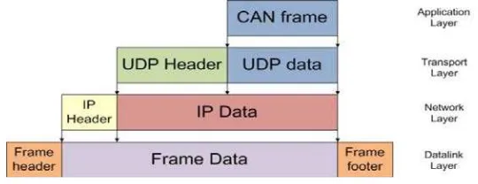
CAN over IP in Wireless LAN has been implemented by encapsulating CAN frame to PLCP packet format [15]. In this study, CAN frames over IP protocol works by encapsulating CAN frames into UDP data payload. The transmission CAN frame used is CAN-FD with a length of 64 bytes of data fields. The layers of the protocol used to accommodate CAN frame over IP is illustrated in Figure 1.
2.3. Error Correction Coding (ECC)
ECC is used in a data transmission system which has noise and error [16]. ECC checks every bit of data transmitted in the network. The error detection process can be done using various methods, such as Cyclic Redundancy Check (CRC). CRC of each data packet sent is calculated by the method of operation of digital logic. If the CRC detects data transmission errors, ECC will correct the data by request the previous data to the sender using Automatic Repeated Request (ARQ).
2.4. Interplanetary Overlay Network (ION)-DTN
The software used in Telemetry and Telecommand Management (TMTC) system is ION-DTN 3.2.0 with a two-node ring connection. ION-DTN is a software that is intentionally designed to provide Disruption/Delay Tolerant Network (DTN) communication in space [17]. DTN protocols are divided into the application layer, transport layer, network layer, data link layer and physical layer, with an additional layer (bundle layer) [18].
ION is designed to perform DTN communication in a way that is cost-efficient, such as robotic spacecraft. The main purpose of ION-DTN operation is to reduce cost and risk in space communication by simplifying the construction and processing of automated digital data communication networks, such as space links, planetary surface links, and terrestrial links.
2.5. Triple Modular Redundant System
Redundancy is an approach to improve the reliability and availability of a system. Redundancy is implemented when the cost of failure is high enough making the system shut down. There are many models that are commonly used to model redundancy. The three main models are Standby Redundancy, N Modular Redundancy, and 1/N Redundancy. In this study, N Modular Redundancy is implemented in the system.
The only factor that can have an impact on reliability is the failure rate. Therefore, the reliability of the system is best influenced through prudent part selection and design practices. By looking at the reliability equation, we can see that the probability of success can be significantly improved by leveraging the approach of redundancy. By using redundancy, the system downtime is dependent on how fast the system switches automatically over to the backup unit if the redundant modules fail.
3. Research Method
In this study, fault-tolerant systems were implemented in hardware redundancy consisting of OBC, ECC and Telemetry and Tele-command Management (TMTC) using ION-DTN.
3.1. Hardware Design
The hardware design of the OBC system for the satellite is done by integrating various modules, the main of which comprises three OBCs and one passive switch. Figure 2 shows the hardware of the OBC system. The OBCs communicate with each other when Ethernet cables have been plugged into the switch in a network. Each OBC has a different priority, the highest one being to communicate with the GS and the other two functioning to collect the sensor data. The hardware schematic of the communication system can be seen in Figure 3.
3.2. Error Correction Coding Design DESIGN:
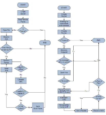
CAN frame over IP protocol is implemented using Linux socket programming and socket CAN. The data transmission utilizes the concept of client and server. Figures 4 and 5 illustrate the data transmission process for both the client and server respectively.
IMPLEMENTATION:
ECC implementation in the application layer was applied by calculating the CRC of transmitting CAN frames. A standard CRC of a 15-bit CAN bus can be represented by a polynomial as follows:
Figure 2. On-board Computer Figure 3. Hardware Schematic of Data Transmission
Based on the above polynomial, the hex-based representation is 0x4599 (MSB-first code). The CRC calculation process was performed on all bits in the CAN frame. It starts from the arbitration field and continues until the data field. CRC calculation on these bits generated 15 bits of CRC that were filled into the CRC field of the CAN frame. CAN frame over IP programming utilized the socket CAN Linux programming and the CAN data frame used the socket CAN library.
CRC calculation on socket CAN is usually performed at the CAN controller in the form of hardware with a specific function. For CAN frames over IP as in this case, CRC calculation was used as part of the ECC calculation data transmission with the UDP protocol. CRC field has 15 bits, but the number of bits in C programming is about 8-bit value multiples. To solve this problem, the CRC calculation bits were moved with a left shift bit operation before being placed in the CRC field. The CAN data frame received by the receiver was equipped with a CRC field which contained a certain value. Subsequently, the receiver processed the verification of the received CRC values.
The CRC verification would be a standard for successful data transmission. If the result of the CRC calculation on the part of the receiver generated a zero value, the data transmitted would be true or correct. The client would then not send the error frame to the server. Instead, the client would simply send a notification to resume sending the data. Software implementation of ECC of the client has the main purpose of verifying the received CRC. Similarly, the CRC verification process aims to determine whether the client should send error frames to the server. Testing simulation continued with the condition that when there is no change in the encoder output data, this data would be the input data of the decoder. The client was then asked to send the next data. Furthermore, the input of decoder changes manually with the wrong value before the client calculates the CRC. The data in Figure 6 is manually input.
Figure 6. Input for CRC Validation Testing
The user had to change the file ‘output.txt’ in order to change the input of the decoder as shown in Figure 7.
Figure 7. File ‘output.txt’ Changed Manually Figure 8. Error Data and Client Request for the Previous Frame
After the input of the decoder passed the calculation, the program would find an error in the transmission of data so that the server had to resend the packet as shown in Figure 8. The file ‘output.txt’ would automatically be changed by the server when it received notification of the error occurring in data transmission.
3.3. Telemetry and Tele-command Management Design DESIGN:
The software designed in the development of the redundant system is primarily based on the synchronization of connections among the three OBCs. OBC-1 acts as the default of primary OBC. As the primary OBC, its function is to send data to GS, while also accepting and broadcasting software upgrades from GS to the other OBCs. Data transmitted from OBC-1 to GS is taken from the other OBCs.
By default, OBC-2 is the supporting OBC that processes and transmits platform data to OBC-1. OBC-2 would also be taking OBC-1’s role as the primary OBC if OBC-1 failed.OBC-3 plays a role as a supporting OBC alongside OBC-2. OBC-1 would request data from OBC-3 if OBC-2 failed. OBC-3 would also take over OBC-1’s role to communicate with GS if both OBC-1 and OBC-2 failed.
The main script of each OBC works by calling other scripts containing the programs that run each sub-section of each task (retrieval and dissemination of data, communication of data to GS, and the process of updating the software).
In a redundant system, the system is designed to be mutually synchronized with one another via a data communication process. There are two different scenarios governing the possible actions of the OBCs, i.e. when connected with GS and when not connected. The combinations of actions that may occur following the two scenarios are described in Figures 9 and 10.
IMPLEMENTATION:
The testing was done by simulating data transmission between OBCs via an Ethernet cable, without data corruption and delay. The goal to obtain the performance of data request between OBCs, total packet acquired between OBCs and first accumulated packet sent time between OBCs and GS under normal circumstances.
The testing was done on all scenarios, excepting the scenario where all OBCs failed simultaneously. Dummy data were transmitted, and each scenario was repeated five times in order to obtain an averaged result. Each scenario was tested using Low Earth Orbital time consideration, which stood at around 100 minutes. OBC-GS communication duration was assumed to be 10 minutes. There was 90 minutes during which each OBC was disconnected from the GS. If every scenario, excepting that when all OBCs failed, were assumed to have happened during that period, then each scenario had around 13 minutes duration.
Figure 9 Redundancy Scenario: Disconnected with GS
Figure 10 Redundancy Scenario: Connected with GS
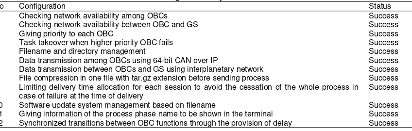
Table 1. List of Configuration System and Test Result
No Configuration Status
1 Checking network availability among OBCs Success
2 Checking network availability between OBC and GS Success
3 Giving priority to each OBC Success
4 Task takeover when higher priority OBC fails Success
5 Filename and directory management Success
6 Data transmission among OBCs using 64-bit CAN over IP Success
7 Data transmission between OBCs and GS using interplanetary network Success
8 File compression in one file with tar.gz extension before sending process Success
9 Limiting delivery time allocation for each session to avoid the cessation of the whole process in
case of failure at the time of delivery
Success
10 Software update system management based on filename Success
11 Giving information of the process phase name to be shown in the terminal Success
12 Synchronized transitions between OBC functions through the provision of delay Success
When the OBC was not connected with the GS, the operation was done in the form of data transmission between OBC operations. The results obtained were in the form of data sending reliability between OBCs in various scenarios. Each scenario was tested in 13 minutes duration.
4. Results and Analysis
4.1. Error Correction Coding (ECC)
Table 2 shows the result of the Error Correction Coding experiments. Table 2 shows that the average transmission time is proportional to the corruption percentage of the data. The longest time of transmission data occurred at 84.472 seconds. ECC test indicates that data transmission using CAN frames over IP managed to correct the corrupted data up to 10 %.
Table 2. Transmission Time for Each Percentage of Data Corruption
Data
Satellite bus utilizing CAN has limited transmission speed at 1 Mbps [11, 12]. But with CAN frame over IP, data transmission can be done via Ethernet with transmission speed up to 10/100 Mbps. CAN frame over IP method in this research can improve the reliability of the OBC communication system design. The error detection method used is not just limited to the standard error detection in CAN. Even the Forward Error Correction (FEC) code like Reed Solomon, BCH, and Hamming Code can be used in a system designed [19-21].
4.2. Telemetry and Tele-Command Management
Table 3. Delay Data for Various Altitudes of Satellite Orbit
Low Earth Orbit Medium Earth Orbit GEO and High Earth Orbit
Altitude (km) Delay (ms) Altitude (km) Delay (ms) Altitude (km) Delay (ms)
100 0.67 6000 40 35786 238.6
2000 13.3 20000 133.3 50000 333.3
Table 4. TMTC Transmission Time for Varying Values of Data Corruption Percentage and Delay as Repeated for 50 Experiments
The test results demonstrate the success of the system’s tolerance to failure, by being able to sustain the transmission of data despite the malfunctioning of OBCs. The data would continue to be acquired until all OBCs would have failed.
At this time, in addition to a process of exchanging data between OBCs is also a process of sending data to the GS. In addition, the OBC which served as the main OBC would also spread shipment of GS data, which was the script and the source code that had been updated to then be compiled and run on each targeted OBC. In this case, the first packet size that was accumulated during OBC-GS disconnection was measured using the maximum packet size acquired, i.e. 6,299,264 bytes per 13 minutes. For the 90 minute duration, the accumulated packet size was around 44.1 MB. This was the first packet data size to be delivered to GS, of which the related sent time is shown in the Table 5 and Table 6.
Table 5. Testing Results (When OBCs are disconnected from GS)
OBC-1 OBC-2 OBC-3 Request
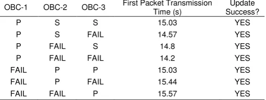
Table 6. Testing Results (When OBCs are connected from GS)
OBC-1 OBC-2 OBC-3 First Packet Transmission
In this research TMR is tested in data transmission with size of satellite data over 40 MB. Several studies have also implemented fault-tolerant system on OBC satellite such as Fault-Distributed Tolerant and centralized redundant [22]. But it has not been tested for sending dummy data up to 40 MB. FTD-OBC Research only compensated fault at architectural level [22]. Fault-tolerant OBC with TMR method designed in this research can improve system reliability at hardware functional level. This method will have a better performance if combined with FTD-OBC method that works at architecture level.
The test results show the success of the system’s redundancy by successfully transmitting data from OBC to GS despite the failure that happened on two out of three OBCs at the same time. Software upgrade was successfully delivered and processed, but could only be implemented on the OBC that was still active during the delivery process of data from GS to OBC.
5. Conclusion
The ECC can be implemented on OBCs which consist of three Intel Galileos and a passive switch. The ECC system designed using the CAN frames over IP protocol performs well and is able to transmit data with a corruption percentage of 10% in 84.472 seconds. Transmission process using ION-DTN in TMTC is able to perform properly in a data transmission to GEO orbit with delay, up to an altitude of 50000 km and data corruption percentage of 2%. Redundant systems can operate synchronously to establish data communication between OBCs. Remote software update can be successfully performed under all designed scenarios.
References
[1] Petrovic V, Schoff G, Stamenkovic Z. SEU and SET Fault Injection Models for Fault Tolerant Circuits. 13th Biennial Baltic Electronics Conference (BEC). Tallinn. 2012: 73-76.
[2] Zhenyong W, Qing G, Xuemai G. Comprehensive Computational Analysis on TCP in Satellite Links. First International Conference on Innovative Computing, Information and Control (ICICIC). Beijing. 2006: 716-721.
[3] Caini C, Cruickshank H, Farrell S, Marchese M. Delay- and Disruption-Tolerant Networking (DTN): An Alternative Solution for Future Satellite Networking Applications. Proceedings of the IEEE. 2011; 99(11): 1980-1997.
[4] Hou R, Zhao S, Yao Z, Xu J, Li X, Fang S. Influence on the Bit Error Ratio of the Optical Satellite Communication System under Space Radiation Environment. Symposium on Photonics and Optoelectronics (SOPO). Shanghai. 2012: 1-4.
[5] Marshall P, Dale C, Carts M, LaBel K. Particle-induced Bit Errors in High Performance Fiber Optic Data Links for Satellite Data Management. IEEE Transactions on Nuclear Science. 1994; 41(6): 1958-1965.
[6] Patton S, Frasca A, Talnagi J, Hyman D, Phillips B, Jones J, Vaia R, Voevedin A. Effect of Space Radiation on the Leakage Current of MEMS Insulators. IEEE Transactions on Nuclear Science. 2014; 60(4): 3074-3083.
[7] Chitra P, Ramakrishnan VN. Effect of Underlap and Its Soft Error Performance in 30 nm Junctionless Based 6T-SRAM Cell. Telkomnika. 2015; 13(2): 451-459.
[8] Xiaoxi R, Chu W, Yu D. Single-Event-Upset Mitigation Placement and Routing Algorithms for Field-Programmable Gate Arrays.Telkomnika. 2014; 12(10): 7422-7429.
[9] Kelkar S, Rajkamal. Control Area Network based Quotient Remainder Compression-Algorithm for Automotive Applications. 38th Annual Conference on IEEE Industrial Electronics Society (IECON 2012). Montreal. 2012: 3030-3036.
[10] Postolache M, Neamtu G, Trofin SD. CAN-Ethernet Gateway for Automotive Applications. 17th International Conference on System Theory, Control and Computing (ICSTCC). Sinaia. 2013: 422-427.
[11] Kimm H, Jarrel M. Controller Area Network for Fault Tolerant Small Satellite System Design. IEEE 23rd International Symposium on Industrial Electronics (ISIE). Istanbul. 2014: 81-86.
[12] Khurram M, Zaidi SMY. CAN as a Spacecraft Communication Bus in Leo Satellite Mission.
Proceedings of 2nd International Conference on Recent Advances in Space Technologies (RAST).
Istanbul. 2005: 432-437.
[13] Ghani M, Jusoh W, Hanafiah M, Raman S, Jano Z. A Review of Communication Protocols for Intelligent Remote Terminal Unit Development. Telkomnika. 2013; 11(4): 819-826.
[15] Bayilmis C, Erturk I, Ceken C. Extending CAN Segments with IEEE 802.11 WLAN. The 3rd ACS/IEEE International Conference on Computer Systems and Applications. Cairo. 2005.
[16] Kaneko H. Error Control Coding for Semiconductor Memory Systems in the Space Radiation Environment. Proceedings of the 20th IEEE International Symposium on Defect and Fault Tolerance in VLSI System (DFT’05). Monterey. 2005: 93-101.
[17] Hu J, Wang R, Sun X, Yu Q, Yang Z, Zhang Q. Memory Dynamics for DTN Protocol in Deep-space Communications. IEEE Aerospace and Electronic System. 2014; 29(2): 22-30.
[18] Husni E, Fauzan M. Design and Implementation of Bundle and Network Layer in Tactical Text Messaging Radio using Delay Tolerant Network (DTN). Advanced Science Letters. 2015; 21(1): 52-56.
[19] Barukang L. Reed-Solomon codes for Uncompressed IP Header Protection. International Conference on Computer Applications and Industrial Electronics (ICCAIE). Kuala Lumpur. 2010: 29-33.
[20] Prasad AR, Shinohara Y, Seki K. Performance of Hybrid ARQ for IP Packet Transmission on Fading Channel. IEEE Transactions on Vehicular Technology. 1999; 48(3): 900-910.
[21] Xu J, Zhang T, Dong Z. On Forward Error Correction with Hamming Code for Multi-Path Communications. International Conference on Wireless Communications and Signal Processing (WCSP). Huangshan. 2012: 1-5.